
Electrical CAD block attributes connect reusable symbol geometry with information that changes from one drawing instance to another. Their value is not simply faster labeling; a well-governed attribute structure can help drafters coordinate plans, schedules, diagrams, and equipment records without surrendering control of the plotted document.
The key is to treat attributes as part of the drawing data model. Field names, prompts, visibility, placement, and extraction rules should be planned together so that the block remains understandable both graphically and digitally.
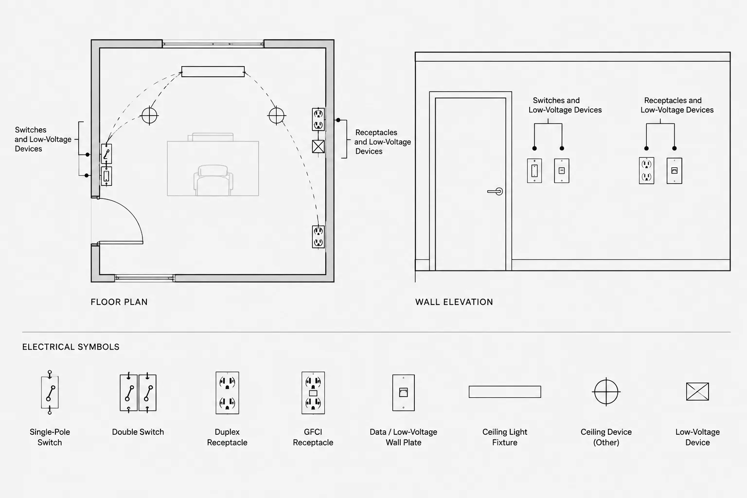
Electrical symbols often begin as simple collections of lines, arcs, and text. That approach may be adequate for a generic symbol library, but project drawings frequently require each symbol instance to carry unique information. A receptacle may need a circuit reference, a panel symbol may need an equipment ID, and a control device may need a zone or sequence designation.
Electrical CAD block attributes provide a structured way to store and display that information. Instead of editing ordinary text beside every symbol, the drafter inserts a block and enters values into predefined fields. When planned carefully, attributes improve consistency, support drawing audits, and make selected information available for schedules or equipment lists. When planned poorly, they can create hidden data, duplicate labels, and confusing update behavior.
This guide explains how to design an attribute workflow that complements an electrical CAD block library while preserving clear graphic standards and project-specific control.
What Is a Block Attribute?
A block attribute is a data field associated with a block definition. The definition establishes the field name, prompt, default value, text appearance, and visibility behavior. Each inserted block reference can then hold its own value for that field.
For example, a generic equipment block might contain attributes for:
- Equipment identifier
- Panel or source reference
- Circuit designation
- Drawing note reference
- System or service classification
- Schedule key
- Manufacturer or model placeholder, when project documentation requires it
The geometry can remain identical across many block instances while the attribute values change. This separates the reusable symbol from the project data assigned to each occurrence.
Attribute terminology and editing tools vary among CAD platforms. Before building a library around them, confirm how the selected application handles field definitions, block redefinition, extraction, visibility, and file exchange.
Visible Attributes and Hidden Data Serve Different Purposes
Not every stored value should appear on the plotted drawing. A practical block may contain both visible annotation and nonprinting data.
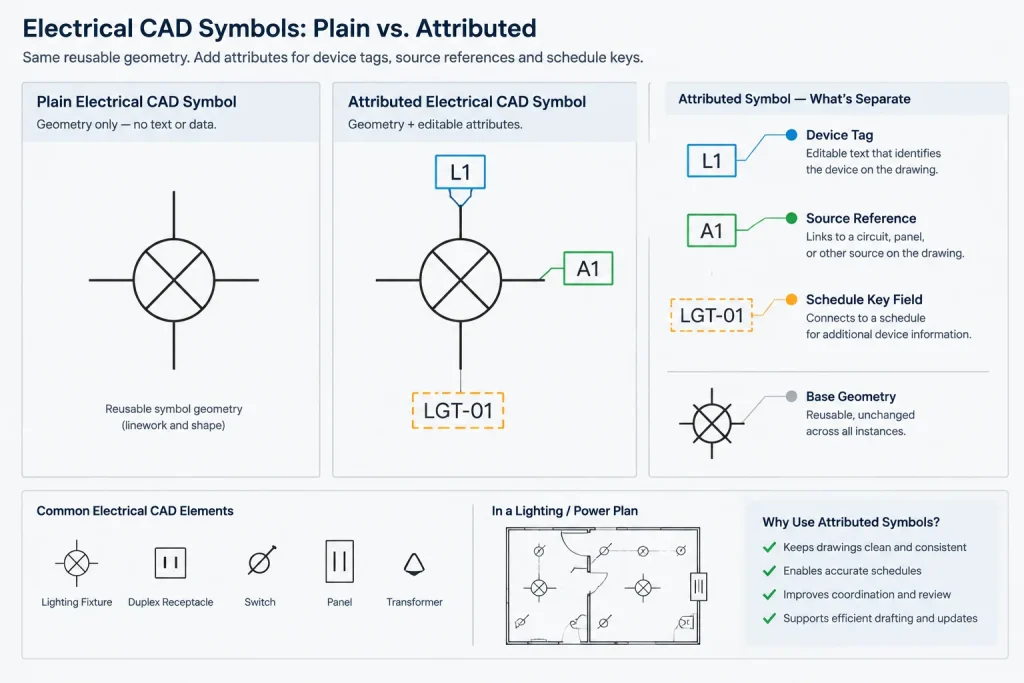
Visible attributes
Visible attributes communicate directly with drawing users. Typical examples include device tags, equipment IDs, circuit references, and keynote numbers. Their text height, orientation, alignment, layer, and plot behavior should follow the project annotation system.
Hidden attributes
Hidden attributes can support internal checking or data extraction without adding visual clutter. Examples may include a library classification, schedule category, source block revision, or internal coordination status.
Hidden fields require discipline because reviewers cannot confirm them from a plotted sheet. If a value affects construction interpretation, it should normally be visible somewhere in the drawing set or represented in a coordinated schedule. Hidden attributes should not become an undocumented substitute for required notes or design information.
Choose Attribute Fields Based on a Defined Use
Adding every imaginable field does not make a block smarter. It makes insertion slower and increases the chance of incomplete or contradictory data. Each attribute should have a specific purpose in the documentation workflow.
| Attribute purpose | Possible field | Primary coordination target |
|---|---|---|
| Identify an item | Device tag or equipment ID | Plans, schedules, and diagrams |
| Show an electrical relationship | Panel and circuit reference | Power plan and panel schedule |
| Connect to notes | Keynote or detail reference | Plan notes and detail sheets |
| Classify an object | System or device category | Legends, counts, and exports |
| Support library management | Symbol family or revision status | Internal CAD quality control |
Before creating a field, ask who will enter it, who will review it, where else the value appears, and what happens when it changes. If those questions have no clear answers, ordinary annotation or a separate schedule may be more appropriate.
Use Stable Attribute Tags and Clear Prompts
An attribute tag is the internal field identifier. A prompt is the instruction shown to the person inserting or editing the block. A default is the value supplied when no replacement is entered.
These elements should not be treated interchangeably. Tags work best when they are stable, concise, and suitable for data processing. Prompts should be understandable to the drafter. Defaults should be safe and obvious rather than appearing to provide verified project information.
For example, an internal tag might identify a source reference, while the prompt asks the user to enter the serving panel and circuit. The default could remain blank or use a clearly incomplete placeholder. A default should never imply that a rating, circuit, equipment designation, or installation condition has already been validated.
Maintain a small attribute dictionary for the library. It can record each approved tag, its meaning, expected value format, visibility, and intended block families. This helps prevent several tags from representing the same concept under slightly different names.
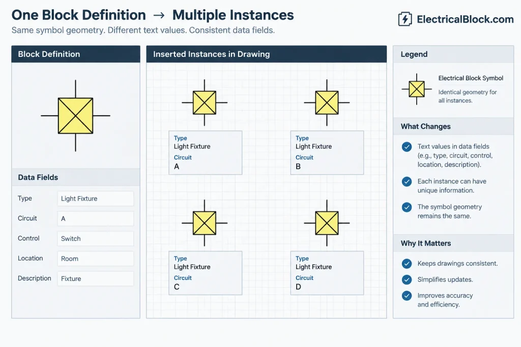
Separate Symbol Geometry from Project Annotation
A common library problem occurs when project-specific text is embedded as ordinary text inside a supposedly reusable block. Copies of the block may then retain outdated room numbers, circuit references, or equipment labels.
A better structure usually divides information into three groups:
- Permanent geometry: the lines, arcs, fills, and connection marks that define the symbol.
- Permanent symbol text: generic letters or identifiers that are truly part of the symbol convention.
- Instance data: attributes that vary from one inserted block to another.
Keep adjacent general notes outside the block when they describe a local condition rather than the identity of the device. This prevents the block from becoming a container for unrelated text and allows note placement to respond to plan congestion.
Plan Attribute Position, Alignment, and Rotation
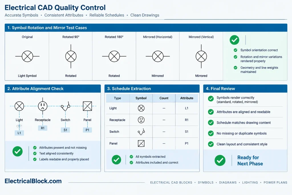
An attribute may be technically attached to a block yet still produce poor drawings. Test the block in the conditions in which it will actually be used: rotated, mirrored, placed near walls, inserted into dense plans, and shown at the intended plotted scale.
Review the following graphic behaviors:
- Whether text remains readable after rotation or mirroring
- Whether the insertion point supports predictable placement
- Whether long values collide with symbol geometry
- Whether attributes use appropriate annotation layers
- Whether alignment remains consistent between short and long values
- Whether blank fields leave awkward punctuation or separators
Do not assume that one attribute arrangement will work for plan, elevation, and diagram blocks. Related block families can share field names while using different text positions suited to each view.
Understand What Happens When a Block Definition Changes
Editing an attribute definition does not always update existing block references in the same way that it affects new insertions. Depending on the CAD platform and command used, existing instances may retain old positions, values, visibility states, or field structures.
Before redefining a widely used electrical block, create a test file containing representative instances with completed values. Check whether the update preserves unique data and whether attribute synchronization changes text placement or resets properties. Save a recoverable copy before applying a library-wide revision.
This is especially important when:
- Renaming an attribute tag
- Adding or deleting a field
- Changing the order of insertion prompts
- Moving attribute text
- Changing visibility or layer assignment
- Replacing a legacy block with a revised definition
A geometric correction and a data-structure change should be reviewed separately. The second may affect extraction routines and schedules even if the plotted symbol looks unchanged.
Coordinate Attributes with Schedules and Extracted Lists
Attributes can support equipment lists, device counts, or coordination reports, but extraction should be treated as a controlled documentation process rather than an automatic source of truth.
Before relying on extracted data, verify:
- Which block names and field tags are included
- Whether nested, copied, or externally referenced blocks are counted
- How blank and duplicate values are handled
- Whether demolition, future, alternate, or by-others items are distinguishable
- Whether the output represents design intent or only objects currently drawn
A count of inserted blocks may differ from the required quantity if one symbol represents several devices or if typical layouts are reused by reference. The extraction method must match the drawing convention.
A Practical Quality-Control Workflow
Use a repeatable review before releasing an attributed symbol or drawing:
- Confirm that each field has a defined documentation purpose.
- Check tag names against the library attribute dictionary.
- Insert the block and test blank, short, and long values.
- Rotate and mirror test instances where those operations are permitted.
- Plot a sample to review hierarchy and readability.
- Compare visible values with schedules, diagrams, and notes.
- Run a small extraction and inspect missing or duplicate records.
- Test any block redefinition on a copy containing completed project data.
- Remove temporary test blocks and purge only after confirming they are no longer needed.
Keep the Graphic Drawing Authoritative and Reviewable
Electrical CAD block attributes are most useful when they reduce repetitive editing without hiding essential intent. They should reinforce the relationship among symbols, tags, schedules, and diagrams—not create a parallel database that drawing reviewers cannot see.
Start with a limited set of stable fields, document their meaning, and test how they behave through insertion, revision, plotting, and file exchange. Treat extracted information as reviewable project data, and verify all project-specific labels and technical values before issue. With that discipline, attributed blocks can make an electrical CAD library more consistent, searchable, and useful while keeping the final drawings clear.
Decide Where Each Type of Information Belongs
Not every label associated with an electrical symbol should become an attribute. The correct location depends on whether the information identifies a particular block instance, describes a local drawing condition, or belongs to a coordinated project record.
- Use an attribute when a value belongs to a specific symbol instance and may need to be reviewed, filtered, or extracted.
- Use ordinary annotation when text explains a nearby condition and needs flexible placement independent of the symbol.
- Use a schedule or diagram when several related properties must be reviewed together in a controlled presentation.
- Use permanent block text only when the text is an inseparable part of the symbol convention and does not vary between instances.
This separation reduces duplicate information and makes it clearer which location governs when a value changes.
Treat Attribute Names as a Managed Data Structure
Changing an internal attribute tag can affect more than the appearance of a block. Extraction templates, checking routines, schedules, and downstream files may depend on that identifier. A tag change should therefore be reviewed as a data-structure revision, even when the visible prompt or plotted label remains unchanged.
Library documentation should identify the approved tag, its purpose, whether it is visible, the expected type of entry, and the drawing records with which it must coordinate. Ownership should also be clear: someone must maintain the block definition, while project teams remain responsible for validating instance values.
Plan for File Exchange and Project Handover
Attributed blocks may behave differently after translation, export, binding, or import into another CAD environment. A handover review should confirm that symbol geometry remains intact, visible labels retain their intended placement, hidden values remain associated with the correct objects, and extracted records still use recognizable field names.
If another party does not need editable attribute data, the deliverable requirements should still distinguish between the authoritative drawing appearance and any supporting data export. A readable plot or published drawing should not depend on access to hidden fields.
Use Exceptions as a Signal to Improve the Library
Repeated manual overrides often reveal a design problem in the block family. Common warning signs include attributes moved on nearly every insertion, values entered into unrelated fields, duplicate text placed beside the block, or separate block names created only to accommodate annotation position.
Review these exceptions before expanding the library. The appropriate correction may be a better insertion point, an alternate graphic arrangement, a clearer prompt, a separate view-specific block, or removal of a field that does not support the actual workflow.
Frequently Asked Questions
What is the difference between an attribute tag and its displayed value?
The tag is the internal identifier defined in the block. The displayed value is the project-specific information stored in an inserted reference. Many block instances can share the same tag structure while carrying different values.
Should every electrical symbol contain attributes?
No. Attributes are most useful when instance-specific information has a defined coordination, review, or extraction purpose. A simple graphic symbol may be easier to maintain when no structured instance data is required.
Can hidden attributes replace visible drawing notes?
Hidden attributes can support internal classification and data workflows, but they should not be the only location for information needed to interpret the issued drawing. Essential design intent should remain visible or be represented in a coordinated schedule, diagram, or note.
Why do existing blocks sometimes differ after a definition is revised?
An inserted block reference may retain instance values or properties established before the definition changed. The exact behavior depends on the CAD application and update method, so revisions should be tested on a recoverable project copy before broad use.
Are attribute extractions automatically accurate?
No. An extraction reports the objects and fields recognized by its selection and processing rules. Its output still requires review for missing values, duplicates, drawing conventions, referenced content, and symbols that do not correspond directly to required quantities.
When should annotation remain outside the block?
Keep annotation separate when it describes a local condition, requires independent placement, or applies to more than the symbol itself. This prevents reusable blocks from accumulating project-specific notes that may become outdated.

Leave a Reply
You must be logged in to post a comment.