
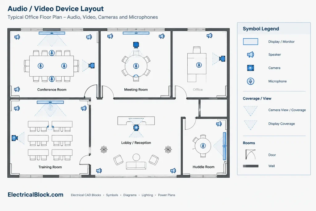
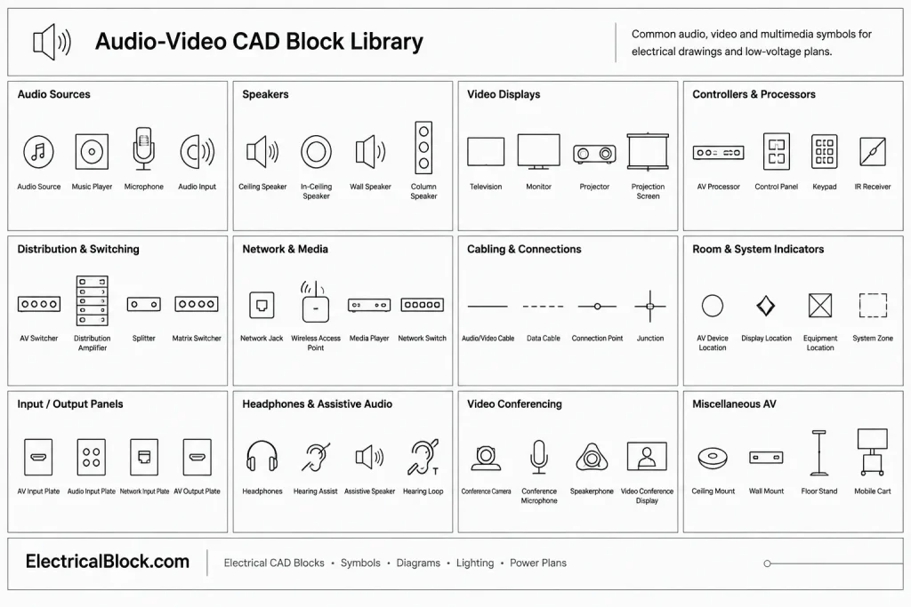
Audio and video symbols provide a consistent graphic language for identifying AV devices within electrical, technology, reflected ceiling, and equipment-layout drawings. This DWG resource supports the documentation of items such as speakers, microphones, cameras, monitors, and related multimedia equipment.
Before adding any block to a project, compare its appearance and meaning with the drawing legend, office CAD standards, and consultant requirements. Symbol conventions can vary between projects, so the legend should remain the controlling reference for interpretation.
Discover a comprehensive DWG file featuring high-quality Audio and Video Symbols CAD blocks, perfect for your next design project. This versatile collection includes standardized symbols for speakers, microphones, cameras, monitors, and other AV equipment, making it easy to create detailed and professional electrical and multimedia layouts. Ideal for architects, engineers, and interior designers, these CAD blocks streamline the planning of audio-visual systems in residential, commercial, or educational spaces. Fully compatible with AutoCAD and other leading CAD software, these symbols ensure seamless integration into your existing drawings, enhancing clarity and efficiency in your technical documentation.
Please log in or register to download this file.
Using AV Symbols in CAD Drawings
Place each symbol in the drawing view where it communicates the device location most clearly. Ceiling-mounted equipment may appear on a reflected ceiling plan, while wall-mounted displays and connection points may be shown on power, technology, interior elevation, or equipment-layout drawings. Avoid duplicating a device across views unless cross-references make the relationship clear.
Review the Blocks Before Placement
- Block definition: Confirm that the geometry behaves as a reusable block rather than unrelated linework.
- Insertion point: Check whether the base point aligns logically with the device center, mounting point, faceplate, or other documented location.
- Layer assignment: Move or map symbols to the appropriate project layers while preserving intended visibility and plotting behavior.
- Text and attributes: Review tags, identifiers, and descriptions for consistency with the equipment schedule and AV legend.
- Drawing scale: Confirm that symbols remain legible without implying the physical size of the represented equipment.
Symbol Meaning and Drawing Coordination
An AV symbol typically identifies a device category rather than defining every product characteristic. Equipment identifiers can connect the plan symbol to a legend, schedule, detail, elevation, or system diagram where additional information is documented. Keep naming consistent so reviewers can follow the same device across the drawing set.
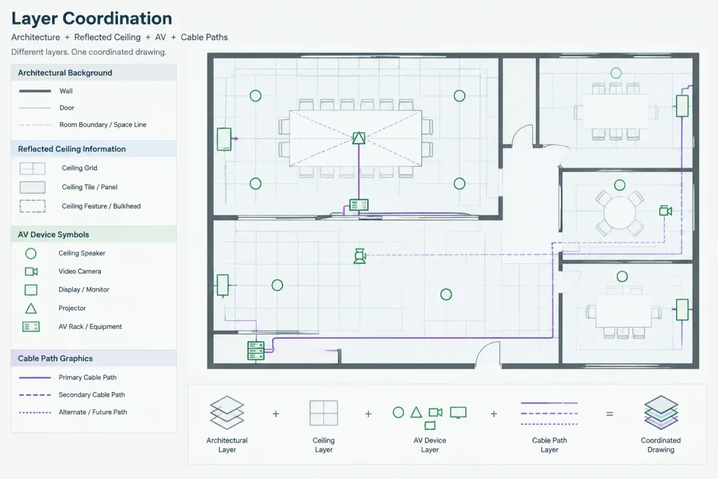
Coordinate AV information with related lighting plans, power plans, ceiling layouts, architectural backgrounds, cable-routing diagrams, and equipment elevations. This helps reveal overlapping symbols, unclear mounting locations, and mismatched device labels before documents are issued.
Recommended Documentation Checks
- Use a project legend that shows each symbol beside its plain-language description.
- Apply a consistent naming pattern to matching devices and drawing callouts.
- Separate AV symbols, annotations, pathways, and background geometry through a clear layer structure.
- Check lineweights, text styles, and plot visibility in the intended sheet presentation.
- Remove unused block definitions only after confirming they are not required elsewhere in the file.
- Have the responsible design professional verify device selection, system relationships, and project-specific requirements.
Related Drawing Topics
This block collection is most useful when considered alongside electrical symbol legends, low-voltage drawing conventions, cable and conduit drafting, equipment layouts, reflected ceiling plans, and CAD layer-management practices. System diagrams can explain functional connections, while plans and elevations communicate physical placement. Keeping those drawing types coordinated produces clearer technical documentation.
Frequently Asked Questions
What equipment can AV symbols represent?
The source collection includes symbols for speakers, microphones, cameras, monitors, and other audio-visual equipment. Review the file and its legend to determine the exact blocks available.
Does an AV symbol show the physical size of a device?
Usually, a plan symbol is a graphic identifier rather than a scaled equipment outline. Use manufacturer information, equipment schedules, elevations, or coordinated layout details when physical dimensions matter.
Should the supplied symbols be added directly to a project legend?
Review each symbol first. Match its description, abbreviation, layer, and graphic style to the project documentation standard before including it in the legend.
How should duplicate or similar symbols be handled?
Compare their intended meanings and retain only the definitions needed for the drawing set. Similar-looking symbols should have clear labels so readers do not confuse different device types.
Can these blocks replace an AV system diagram?
No. Plan symbols identify equipment and locations, while a system diagram communicates functional relationships and signal paths. The drawing types should reference consistent device names and identifiers.
What should be checked after opening the DWG file?
Inspect block behavior, layers, insertion points, text styles, attributes, lineweights, and plotted appearance. Also confirm that the file works correctly within the receiving CAD workflow before incorporating it into project documents.




Leave a Reply
You must be logged in to post a comment.