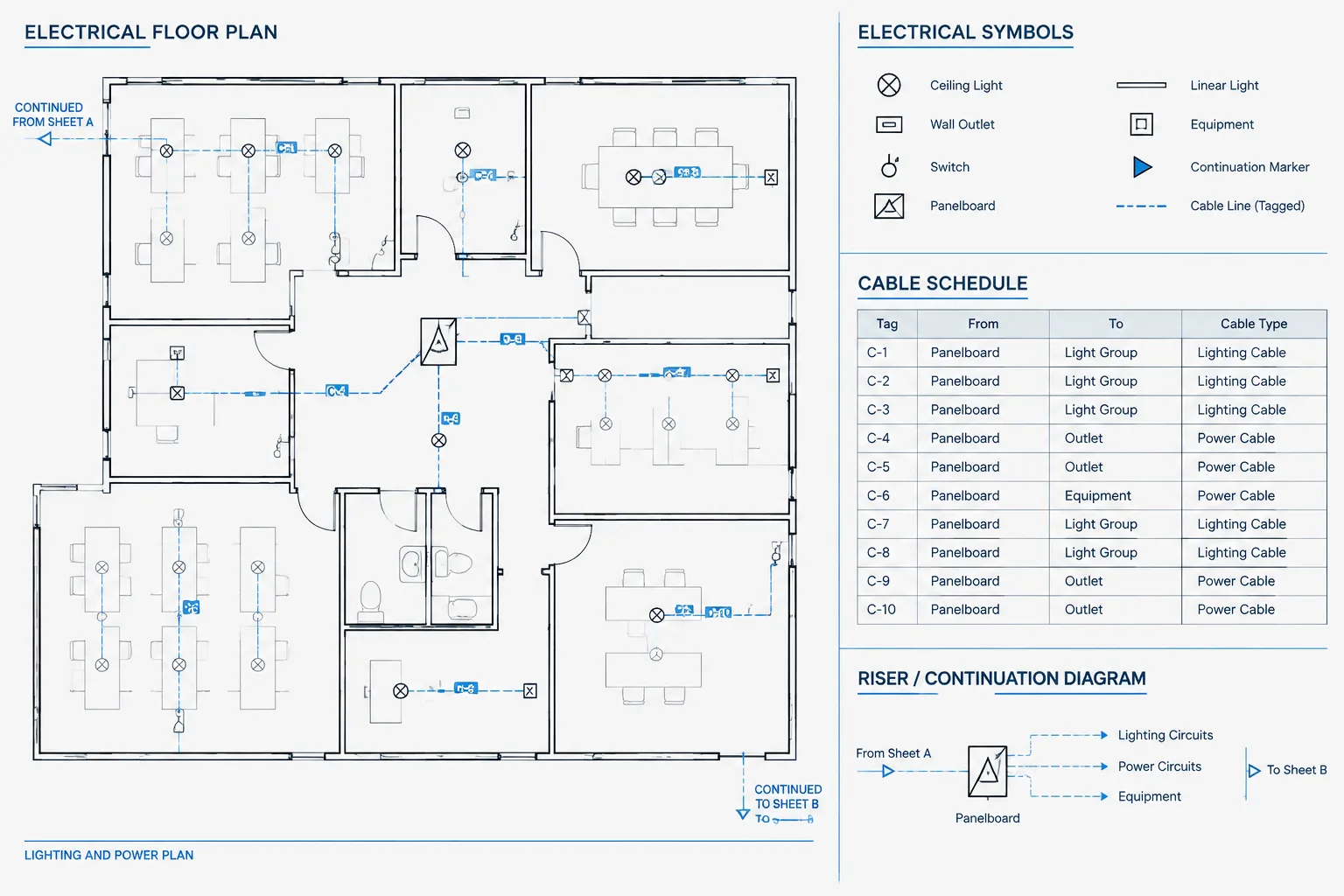
Wire and cable identification in CAD is most effective when every tag acts as a reliable link between graphical connections and project records. This guide explains how to organize identifiers, endpoints, continuation references, attributes, layers, and schedules so that connections can be traced across an electrical drawing set without confusing physical routes with logical relationships.
Electrical drawings often show the same connection in several forms. A floor plan may indicate the route between equipment, a schematic may show its electrical function, a termination drawing may identify individual conductors, and a cable schedule may summarize installation information. Wire and cable identification in CAD provides the common language that connects these documents.
A useful identification system does more than place text beside a line. It distinguishes cables from conductors, supports cross-references, remains readable when drawings are plotted, and gives reviewers a practical way to trace a connection through the drawing set. The exact tag format should follow the project requirements, owner conventions, and verified design data, but the documentation principles are broadly applicable.
Distinguish the Objects Being Identified
Before creating tags, determine what each drawing line represents. A line may indicate a physical cable route, a raceway containing several cables, an individual conductor, a logical circuit, or simply a graphical connection between symbols. Treating all of these lines as interchangeable can produce ambiguous documentation.
- Cable: An assembly documented as one routed item, commonly identified by a cable tag.
- Conductor or wire: An individual electrical path that may require a wire number, terminal reference, or functional designation.
- Raceway: A pathway that can contain one or more cables or conductors and should normally have a separate route or raceway identifier when tracking is required.
- Circuit: A design relationship that may be identified by a panel and circuit reference rather than a unique cable number.
- Signal or net: A logical connection on a schematic that may continue across sheets without depicting its physical routing.
This distinction should be clear in the legend, schedule headings, and drafting conventions. For example, a raceway tag should not be used as though it were a cable tag unless the project explicitly defines that relationship.
Build a Tag Structure Around Document Needs
A tag should be unique enough for the intended drawing set without becoming an encoded sentence. Long tags that attempt to describe system, location, source, destination, service, and status can become difficult to read and maintain. In many workflows, a stable identifier linked to a schedule is more reliable than placing every property inside the tag.
A cable identifier may include a project-defined category prefix and a sequential or database-controlled identifier. A wire number may instead relate to a circuit function, connection point, or control sequence. There is no universal format suitable for every project, so CAD standards should document the chosen structure rather than assume its meaning is obvious.

Useful properties to manage separately
- Unique cable or wire identifier
- Source equipment and source termination
- Destination equipment and destination termination
- Service or system classification
- Cable description based on verified design information
- Route, raceway, or pathway reference
- Drawing status, such as existing, new, future, or removed
- Associated plan, schematic, schedule, or detail references
Not every property belongs in visible plan text. Store frequently revised or lengthy information in attributes, schedules, or managed project data, while keeping the plotted tag concise.
Use From-To References Consistently
A from-to record identifies the two endpoints of a documented connection. It is especially valuable where the graphical route is interrupted, where cables cross several sheets, or where a schedule acts as the primary connection index.
Endpoint names should match equipment tags used elsewhere. If a device is labeled differently on the plan, schematic, and schedule, the connection becomes harder to trace even when the cable number is correct. Establish one equipment identifier and reuse it across applicable documents.
Termination details require another level of consistency. Terminal references should clearly separate the equipment identifier from the terminal designation. Avoid compressed strings that can be interpreted in several ways. Schedule columns are usually clearer than embedding both endpoints and terminals in one long CAD label.
| Document | Primary identification role | Typical coordination check |
|---|---|---|
| Floor or site plan | Shows approximate connection location, route, or pathway relationship | Tag agrees with the schedule and connected equipment |
| Schematic or control diagram | Shows electrical function and logical continuity | Wire numbers and continuation references remain consistent |
| Termination drawing | Shows conductor landing points | Terminal designations match equipment documentation |
| Cable schedule | Provides the indexed from-to record | Each listed tag has valid endpoints and drawing references |
| Raceway drawing | Shows pathway assignment | Cable and raceway identifiers are not confused |
Place Tags for Readability, Not Just Proximity
Identification text should be visually associated with the correct line while remaining legible at the intended plot scale. A tag placed directly over dense geometry may be technically close to its cable but difficult to interpret. Use controlled offsets, leaders, or tag symbols where needed.
On parallel routes, stagger labels or use a structured callout that lists several identifiers in route order. Do not rely only on color because plotted output, grayscale printing, layer overrides, and accessibility needs can remove that distinction. Line type, annotation, and legend information should carry the meaning.

Where a connection continues beyond the view, place the cable or wire identifier near the continuation reference. The receiving location should repeat enough information to confirm continuity. Matching tags at both ends are more dependable than requiring the reader to infer a connection from line position alone.
Separate Physical Routes from Logical Connections
A schematic is generally arranged to explain function, not physical geography. Conversely, a cable routing plan may combine conductors into a shared pathway without showing every electrical relationship. CAD authors should avoid forcing one drawing type to perform both jobs.
On diagrams, wire numbers and cross-references can establish logical continuity between devices and sheets. On plans, cable tags and route references can identify physical connections. The cable schedule then provides a controlled bridge between the two views. Notes and legends should explain whether a line represents a cable, circuit, conduit, or logical signal.
Configure CAD Blocks and Layers for Maintainable Tags
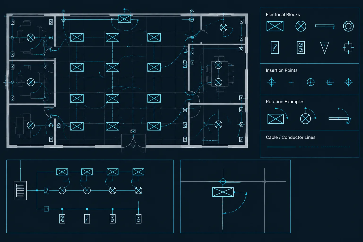
Reusable tag blocks can improve consistency when they are designed around editable data. A cable tag block might contain attributes for the visible identifier, status, and an optional schedule key. A continuation marker may include destination sheet and grid references. Attribute prompts should use plain terminology so that drafters understand what information belongs in each field.
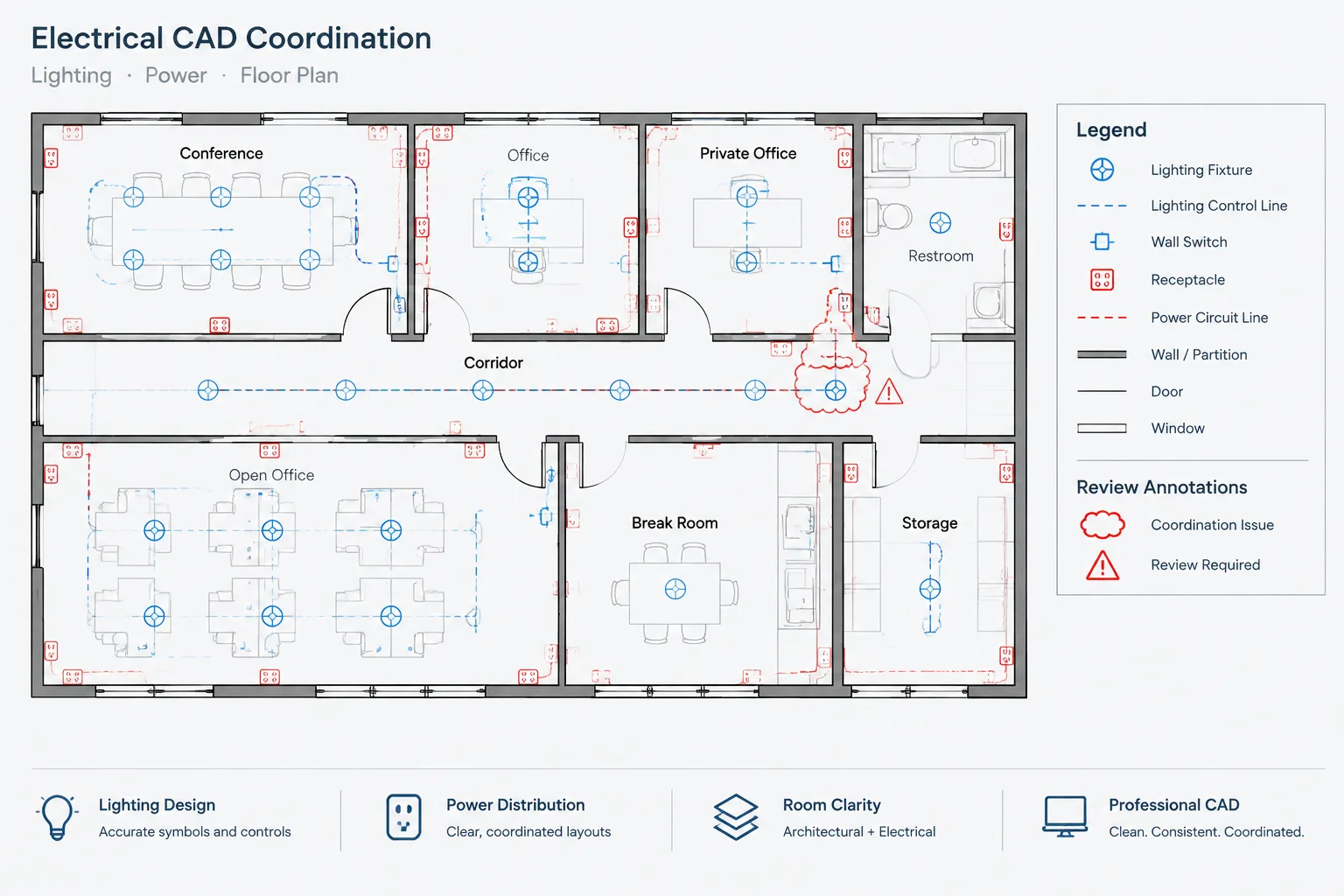
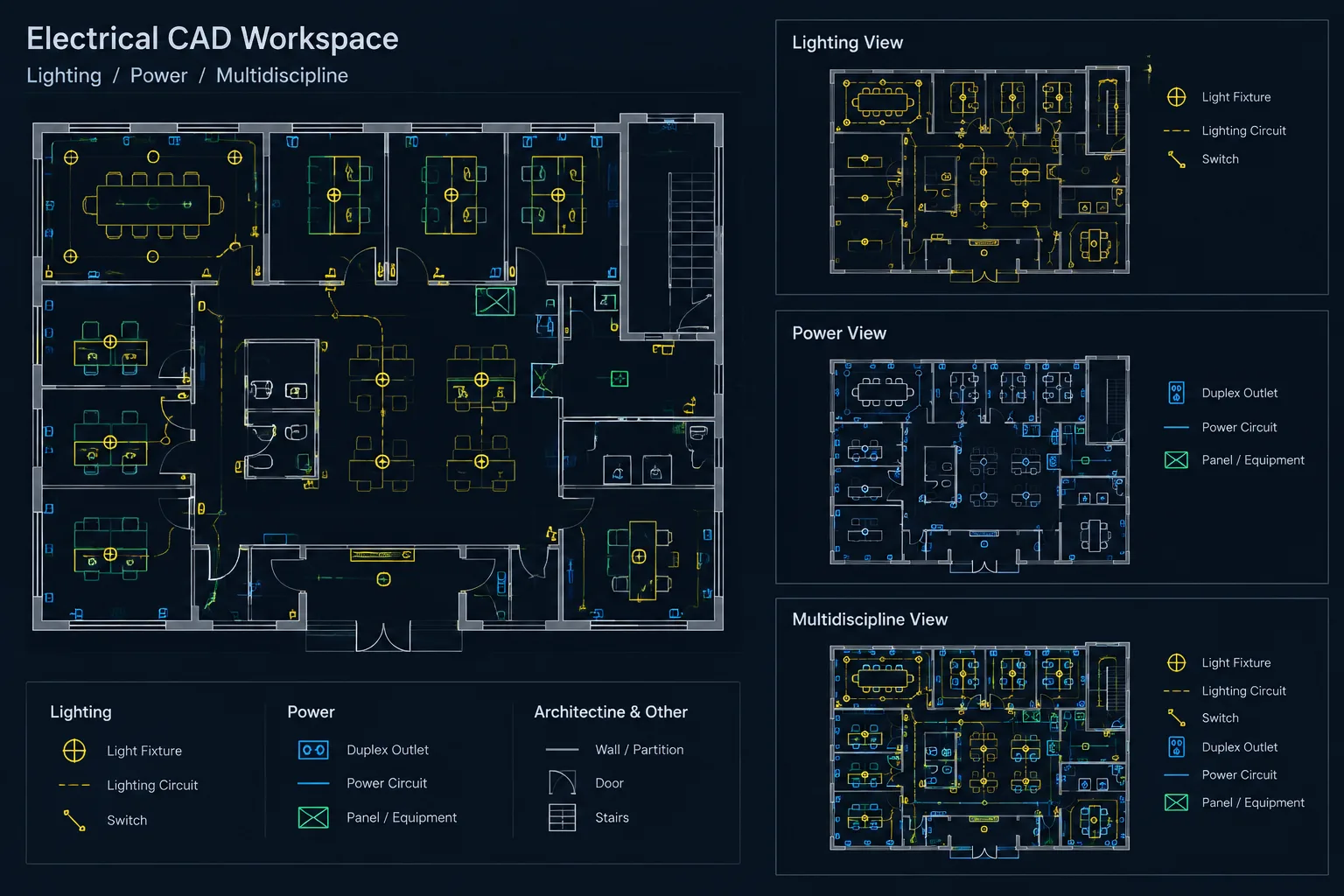
Place tags, connection lines, continuation symbols, and background geometry on appropriately managed layers. Separate layers make it easier to control plan types, screen background information, and isolate identification data during quality review. However, excessive layer separation can make editing cumbersome, so layer structure should support actual deliverables rather than every possible object property.
Avoid exploding identification blocks merely to edit their appearance. Explosion breaks attribute behavior and makes global checking more difficult. If a special condition is recurring, create a controlled block state or approved variation instead of manually modifying individual copies.

Coordinate the Cable Schedule with CAD Drawings
A schedule should not become an independent list that drifts away from the drawings. Whether it is generated automatically or maintained manually, each schedule row should be traceable to graphical documentation or an explicitly defined scheduled-only connection.
Useful checks include:
- Every visible cable tag appears in the relevant schedule.
- Every scheduled cable has valid source and destination equipment.
- Equipment identifiers use the same spelling and punctuation across documents.
- Duplicate cable identifiers are resolved rather than distinguished only by location.
- Continuation references lead to an actual matching reference.
- Removed or future connections are visibly differentiated according to the project legend.
- Wire numbers shown at opposite ends of a continuation agree where continuity is intended.
- Raceway assignments use valid route identifiers and are not mistaken for cable numbers.
Apply a Practical CAD Review Workflow
- Isolate identification layers. Review tags and connection graphics without unrelated background clutter.
- Check uniqueness. Search visible text and block attributes for duplicate cable identifiers.
- Trace endpoints. Follow each selected connection from source to destination, including sheet continuations.
- Compare documents. Verify the plan, diagram, termination drawing, and schedule describe the same relationship.
- Review plotting. Confirm labels, masks, leaders, and line crossings remain understandable in the issued output.
- Resolve unmatched records. Investigate schedule-only and drawing-only identifiers before issue.
Automated extraction can assist with finding duplicates and missing entries, but it cannot determine whether a connection expresses the correct design intent. A final review still requires someone who understands the drawing relationships.
Create a Traceable Documentation System
Effective wire and cable identification in CAD is based on controlled relationships rather than elaborate label formats. Unique tags, consistent equipment names, clear from-to records, and coordinated continuation references allow readers to move confidently between plans, diagrams, schedules, and termination drawings.
The final system should be documented in the project legend or CAD execution guidance and verified against project-specific requirements. CAD blocks and schedules are tools for expressing the design; they do not establish cable selection, electrical suitability, or installation compliance on their own.
Revision and Handoff Controls
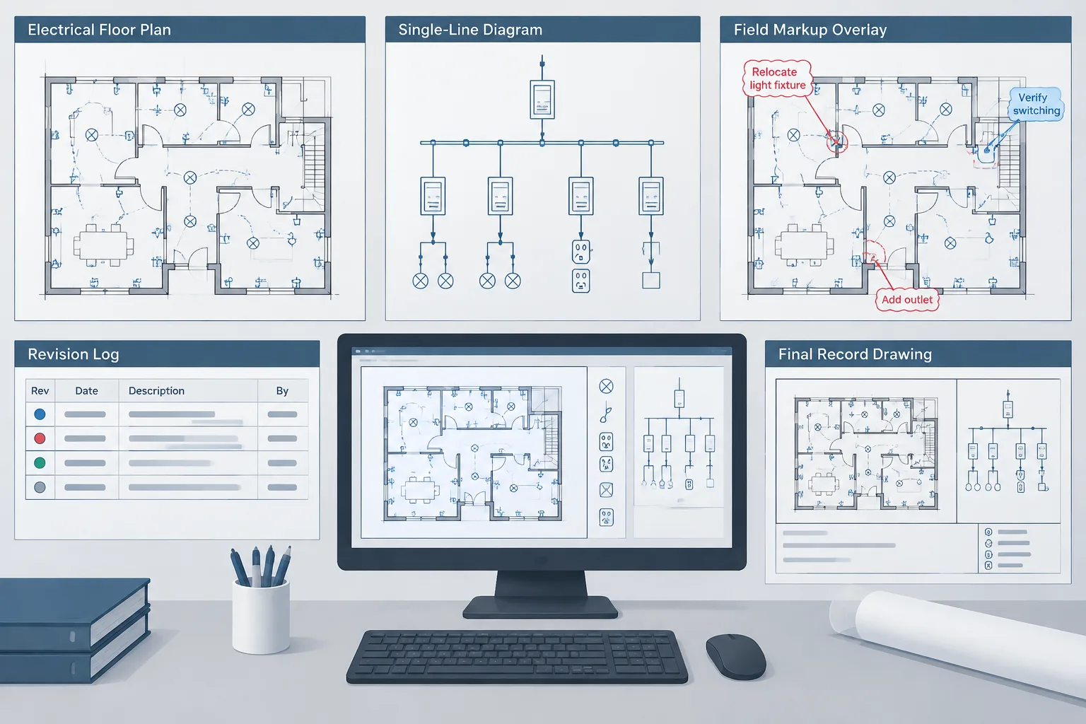
Identification data should remain coordinated as drawings move through review, revision, and final handoff. A changed equipment tag, endpoint, route assignment, or drawing reference can affect several documents even when the cable identifier itself remains unchanged.
When revisions occur, review the full relationship rather than editing only the visible label. The corresponding block attributes, schedule record, continuation marker, termination reference, and equipment designation may also require coordination.
Information to verify before drawing issue
- Identifier ownership: Confirm which drawing, schedule, or managed data source controls the official cable or wire identifier.
- Revision consistency: Check that changed endpoints and equipment names have been updated wherever the connection appears.
- Status clarity: Make sure existing, new, future, and removed connections follow the same graphical conventions used elsewhere in the drawing set.
- Attribute completeness: Review tag blocks for blank, obsolete, or manually overridden attribute values.
- Deliverable readability: Inspect the issued output rather than relying only on the CAD model view.
- Schedule alignment: Confirm that exported or manually maintained schedule data reflects the current drawing revision.
A clear source of record reduces conflicting edits. If information is managed in a schedule or project database, visible CAD annotations should be generated from or checked against that controlled data whenever the workflow permits. If CAD attributes are the primary source, their formatting and field use should be documented so later editors can maintain them consistently.
Use Identification Data Without Overstating Design Meaning
A cable tag confirms identity, not electrical suitability. Likewise, a line on a plan may communicate a connection or routing relationship without defining every installation condition. Legends, notes, and schedules should explain the documentation meaning of each symbol while verified design information remains under the control of the responsible project team.
This distinction is especially important when CAD content is reused. A block, tag style, or schedule layout can provide a drafting framework, but its attributes and references must be checked against the current project rather than carried forward as assumed design data.
Frequently Asked Questions
What is the difference between a cable tag and a wire number?
A cable tag usually identifies a cable assembly as a routed item, while a wire number identifies an individual conductor or logical electrical path. The project legend should define how each identifier is used.
What should a from-to reference contain?
It should identify the source and destination using the same equipment designations found on the related plans, diagrams, schedules, and termination drawings. Terminal references can be maintained in separate fields or schedule columns when combining them into a label would reduce clarity.
Should every cable property appear in the CAD tag?
No. The visible tag should remain readable and provide enough information to identify the connection. Longer descriptions, route assignments, status data, and drawing references can be stored in attributes, schedules, or managed project data.
How should connections continuing onto another sheet be identified?
Place the relevant wire or cable identifier beside the continuation reference and repeat enough matching information at the receiving location to confirm continuity. The references should work in both directions and lead to an actual drawing location.
Can color alone distinguish cable types or drawing status?
Color should not be the only distinction because plotting, grayscale output, layer overrides, and display conditions can change its appearance. Combine color with line types, symbols, annotations, or legend-defined status notation.
How can duplicate cable tags be reduced?
Use controlled identifiers, searchable block attributes, and coordinated schedule records. Before issue, isolate identification layers and compare visible tags with the schedule to locate duplicate, missing, or unmatched entries.
Should cable tags and raceway tags use the same identifier?
They should be treated as separate identifiers unless the documented project convention explicitly establishes a relationship between them. A raceway may contain several cables, so using its tag as a cable number can create ambiguity.
Does a CAD cable tag confirm the cable is suitable for installation?
No. A CAD tag supports identification and documentation. Cable selection, installation requirements, and electrical suitability depend on verified design information and project-specific review.
Leave a Reply
You must be logged in to post a comment.