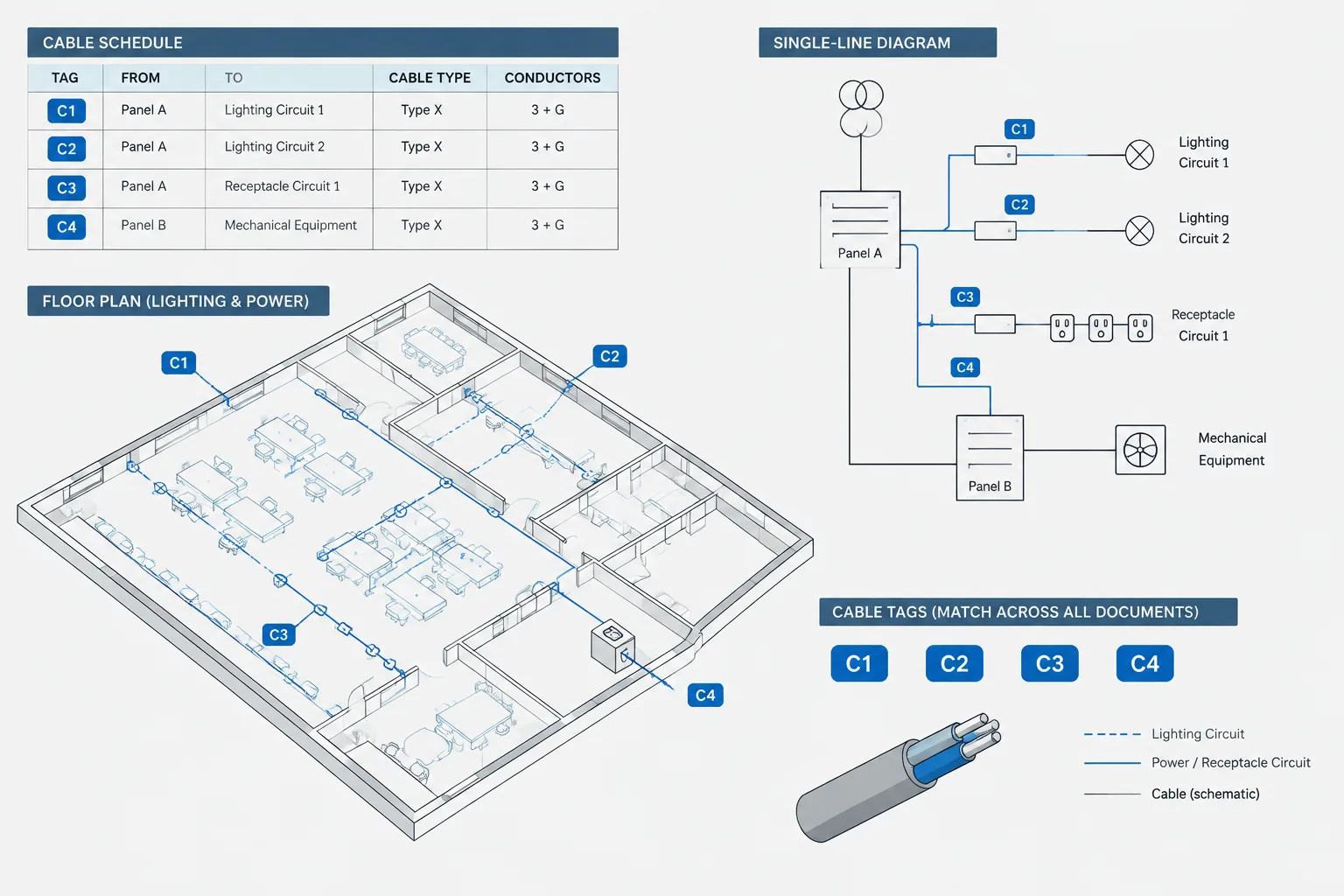
Building an electrical cable schedule in CAD is primarily an information-coordination task. The schedule must connect cable identifiers with equipment tags, routes, diagrams, and termination references while remaining clear enough to revise throughout the drawing process.
The guidance below focuses on schedule structure, CAD organization, drawing coordination, and quality control. Project-specific cable characteristics and connection requirements should always come from approved design documentation rather than assumptions made during drafting.
An electrical cable schedule is a controlled list of cables shown across plans, diagrams, and equipment documentation. It helps the drawing team track where each cable begins, where it ends, how it is represented, and which related drawing defines its route or connection.
A useful schedule is more than a table placed on a sheet. It is part of a coordinated identification system. Cable tags on plans must match the schedule, termination references must agree with diagrams, and route descriptions must remain understandable as the design changes. This guide explains how to structure that information in CAD without turning the schedule into an unmanageable collection of notes.
What an Electrical Cable Schedule Documents
The schedule acts as an index between physical routing drawings and logical connection drawings. Depending on the project, it may cover power, control, instrumentation, communications, security, or other documented cable systems.
A cable schedule commonly identifies:
- A unique cable ID or tag
- The originating equipment, enclosure, or device
- The destination equipment, enclosure, or device
- A service or functional description
- A cable type reference defined elsewhere in the documents
- A route, raceway, tray, or pathway reference when applicable
- Termination or connection references
- Drawing and detail cross-references
- Status, remarks, or revision notes
The exact fields should follow the project documentation requirements. Avoid adding columns simply because they appeared in an older template. Every field creates information that must be maintained and checked.
Cable Schedule vs. Feeder Schedule
A cable schedule and a feeder schedule can contain similar information, but they do not always serve the same purpose. A feeder schedule generally concentrates on distribution relationships documented by panelboards, switchboards, transformers, and other power-distribution equipment. A broader cable schedule may include individual power, control, signal, or communications connections.
The two schedules should not independently describe the same connection unless the project has a defined ownership rule. Duplicate records can drift apart during revisions. If both are required, decide which schedule controls each category of information and use cross-references for the rest.
Plan the Identification System Before Drafting
Each scheduled cable needs an identifier that remains unique throughout the relevant drawing set. A project may organize IDs by system, area, source equipment, destination, or another documented convention. The best format is one the project team can apply consistently and expand without reclassifying existing cables.
Before creating tags, determine:
- Which cable systems belong in the schedule
- Whether IDs are unique across the entire project or only within a system
- How spare, future, removed, or abandoned records will be treated
- Whether one ID represents a cable assembly, an individual cable, or another defined unit
- Which drawing or database is the authoritative source for each field
Do not encode too much technical information into the identifier itself. If an ID contains equipment names, system codes, routes, and cable characteristics, a small design change may force the tag to be renamed everywhere. A stable identifier with separate schedule fields is often easier to maintain.
Recommended Schedule Structure
The following table shows practical field categories rather than mandatory requirements. Project teams should adjust the structure to suit their drawings and review process.
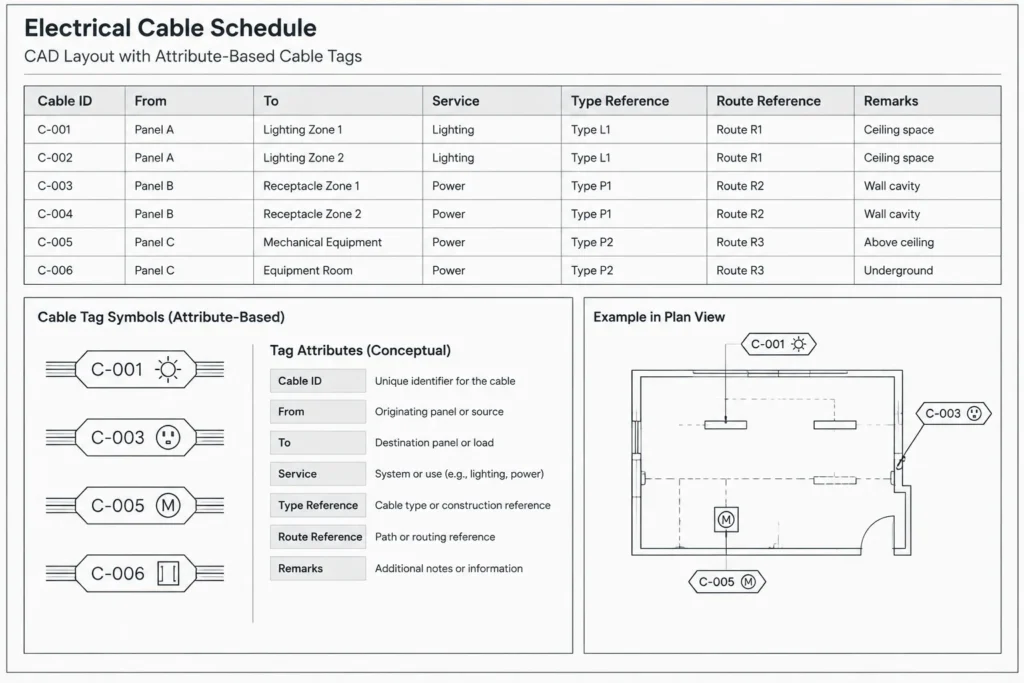
| Field | Purpose | Coordination source |
|---|---|---|
| Cable ID | Provides the unique drawing reference | Project identification convention |
| From | Names the source equipment or device | Plans, diagrams, and equipment tags |
| To | Names the destination equipment or device | Plans, diagrams, and equipment tags |
| Service | Summarizes the cable function | Design documentation |
| Type reference | Points to a defined cable designation | Specifications, legend, or type schedule |
| Route reference | Connects the record to a pathway or route | Plans, tray drawings, or raceway schedules |
| Termination reference | Points to connection details or diagrams | Schematics, wiring diagrams, or terminal drawings |
| Remarks | Records limited project-specific clarification | Design review and revision notes |
Keep the wording in the From and To fields aligned with equipment tags. If a plan labels an enclosure one way and the cable schedule uses a different abbreviation, reviewers may interpret them as separate items.
Coordinate Cable Tags with CAD Plans
Place tags where they add traceability
A cable tag should help a reader connect a drawn segment to its scheduled record. Place it near the applicable line, home run, pathway, or connection without obscuring architectural backgrounds or other electrical annotations. Where a route is congested, use leaders or grouped callouts rather than stacking unreadable text over the linework.
Not every segment needs a repeated label. Establish a consistent rule for where tags appear, such as near origins, destinations, transitions, or continuation points. Repeating tags can improve clarity across separated views, but excessive repetition increases the number of locations that must be revised.
Distinguish cables from pathways
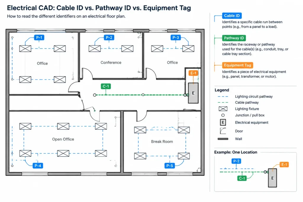
A cable ID is not necessarily a conduit, tray, or pathway ID. Several scheduled cables may share one pathway, and one cable route may pass through multiple referenced pathway segments. Use separate tag formats or prefixes so readers do not confuse the contained cable with the route carrying it.
If the drawing does not show individual cable routes, the schedule should not imply a level of routing certainty that the plans do not provide. Use route fields only to the extent supported by the project documents.
Handle continuation points clearly
When a cable crosses a match line, continues to another floor, or transfers to a different drawing type, show a continuation reference that identifies the destination view or sheet. The cable ID should remain consistent on both sides of the transition. Avoid creating a new ID merely because the same connection appears on another sheet.
Coordinate with One-Lines, Schematics, and Wiring Diagrams
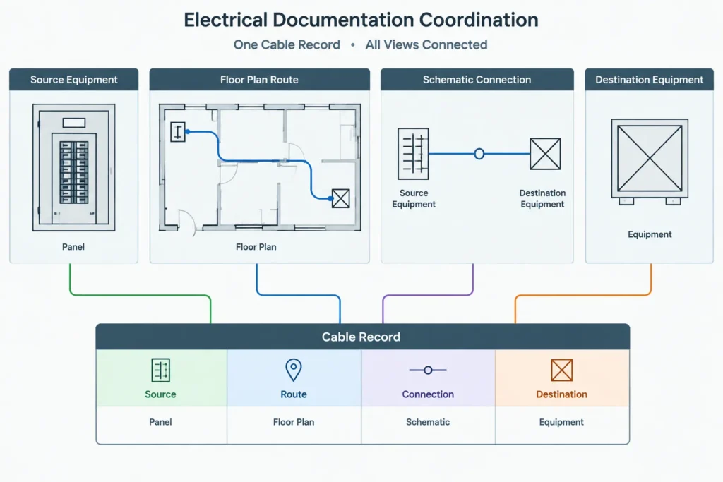
Different drawing types describe different aspects of the same connection. A floor plan may emphasize location and routing, while a schematic emphasizes function. A wiring or terminal diagram may show detailed connection points. The cable schedule links these representations but should not attempt to reproduce all of them.
During coordination, confirm that:
- Source and destination tags match the equipment shown on related drawings
- The documented service agrees with the functional diagram
- Terminal or connection references point to an actual drawing location
- Cables shown only on diagrams are intentionally included or excluded from the schedule
- Removed equipment does not leave orphaned cable records
- Parallel or redundant connections are individually distinguishable where required
Use the schedule as an index, not as a substitute for diagrams. Dense connection logic is usually clearer in a schematic or wiring drawing than in a remarks cell.
Choose a Reliable CAD Workflow
A small schedule can be drafted as a CAD table, but larger schedules are often easier to maintain from structured source data. Whichever method is used, assign clear responsibility for editing the master record. Simultaneously maintaining unrelated CAD tables, spreadsheets, and diagram notes invites inconsistencies.
For a CAD-based workflow:
- Use a consistent table style for headers, rows, text, and borders
- Keep schedule graphics on dedicated electrical schedule layers
- Use attributes or structured object data for cable tags when practical
- Avoid exploding tables or tags into disconnected lines and text
- Reserve enough layout flexibility for added records and revised descriptions
- Split long schedules using clear continuation headings and repeated column headers
If cable tags contain attributes, use the same field names and formatting rules throughout the block library. Attribute extraction can assist checking, but extracted information still requires review against plans and diagrams.
Manage Revisions Without Losing History
Cable schedules change as equipment moves, system boundaries evolve, and connections are added or deleted. Do not silently reuse an old cable ID for a different connection unless the project’s document-control rules explicitly permit it. Reuse can make revision history difficult to interpret.
When a cable changes, review all associated representations: plan tags, route references, source and destination names, diagrams, details, and schedule remarks. Revision clouds may identify changed drawing areas, but they do not replace a full consistency check.
For removed records, follow the project’s issue-stage conventions. A record might be deleted, retained with a status, or transferred to demolition documentation. The correct approach depends on the drawing purpose and document-control procedure.
Quality-Control Checklist
- Every scheduled cable ID is unique within the defined project scope.
- Every visible cable tag corresponds to a schedule record.
- Scheduled source and destination tags exist on the related drawings.
- Plan, diagram, and schedule terminology is consistent.
- Route references use the project’s pathway identification system.
- Continuation references lead to the correct view or sheet.
- No obsolete records remain after equipment or connection changes.
- Table text remains readable at the intended plot scale.
- Column headings and abbreviations are explained where necessary.
- Technical cable information is verified from the project’s approved design sources.
A Schedule Should Improve Navigation
The most effective electrical cable schedule in CAD helps readers move between physical routes, equipment tags, and functional diagrams. Its value comes from consistent identification and controlled coordination, not from the number of columns it contains.
Start with a clear ownership rule for the data, use stable cable IDs, and keep each field tied to a documented source. When plans, schedules, and diagrams are revised together, the cable schedule becomes a dependable drawing index rather than another table that must be interpreted independently.
Turn the Schedule into Controlled Drawing Data
A well-formatted table can still fail if its entries come from inconsistent sources. Before populating the schedule, define which document or structured dataset controls each field. Equipment tags may originate on plans, functional descriptions may come from diagrams, and cable type designations may be maintained in a separate legend or specification reference.
Create a field dictionary
A brief field dictionary helps different contributors enter information consistently. For each column, record what the field means, where its information comes from, which abbreviations are permitted, and how unknown or inapplicable information should be represented. This prevents one drafter from entering an equipment tag while another enters an equipment description in the same column.
Use controlled names and descriptions
Source and destination entries should use the same identifiers found on related drawings. Functional descriptions should follow a consistent naming pattern rather than relying on improvised wording. Controlled terminology improves sorting, filtering, comparison, and review without requiring technical details to be embedded in the cable ID.
Separate design data from drafting notes
Keep approved cable design information distinct from temporary coordination comments. Drafting questions, unresolved references, and review notes should not appear as final technical data. If the workflow requires temporary statuses, make them recognizable and resolve them before the applicable drawing issue.
Use a Repeatable Coordination Pass
Schedule review is easier when performed by information category rather than by reading each row from left to right. Check identifiers for uniqueness, compare equipment names with plans, validate route references against pathway drawings, and then confirm diagram or termination references. This approach makes repeated inconsistencies easier to detect.
Also review the drawings from the opposite direction. A schedule-to-plan check finds records that lack visible drawing support, while a plan-to-schedule check finds tags that were never entered in the schedule. Both directions are necessary because either document can contain an omission.
Prepare the Schedule for Handoff
Before issuing or transferring the CAD files, confirm that the schedule remains editable, its text and borders follow the project layer strategy, and any linked or extracted data can be traced to its controlled source. Avoid workflows that leave the recipient with disconnected text, unidentified abbreviations, or a table that cannot be reliably updated.
If the project uses an external dataset, preserve an issue-specific record according to the document-control process. The published schedule and its source data should represent the same design state so later reviewers can understand what was issued.
Frequently Asked Questions
Should a cable schedule be created directly in CAD or linked from structured data?
Either approach can work. A CAD table may be practical when the schedule is limited and maintained by a clearly assigned editor. Structured source data can be easier to sort and validate when many records are involved. The important requirement is to define one authoritative source and avoid maintaining competing versions.
Should a cable receive a new ID when it crosses a sheet or match line?
Not merely because its drawing representation continues elsewhere. The same documented connection should retain its cable ID, with continuation references showing where the route or connection resumes. A new identifier should reflect the project’s identification rules, not a sheet boundary alone.
How should an uncertain cable route be shown in the schedule?
Do not present an unconfirmed route as established information. Use the project’s approved status, remarks, or coordination method to identify unresolved data, and update the record when the route is supported by the design documents.
Is a cable ID the same as a conduit or tray ID?
No. A cable identifier refers to the scheduled cable record, while a conduit, tray, or pathway identifier refers to the route that carries cables. Keeping these identifiers visually and structurally distinct reduces confusion when cables share pathways or pass through multiple route segments.
Should full cable descriptions be repeated in every drawing tag?
Usually, the tag should provide the identifier needed to locate the controlled schedule record. Repeating extensive data in multiple locations increases maintenance effort and the risk of conflicting descriptions. The amount of displayed information should follow the project’s documentation requirements.
What should be checked before the schedule is issued?
Confirm that cable IDs are unique, visible tags have corresponding records, source and destination names agree with equipment tags, cross-references lead to valid drawing locations, obsolete records have been addressed, and the table remains legible in the intended sheet output.






Leave a Reply
You must be logged in to post a comment.