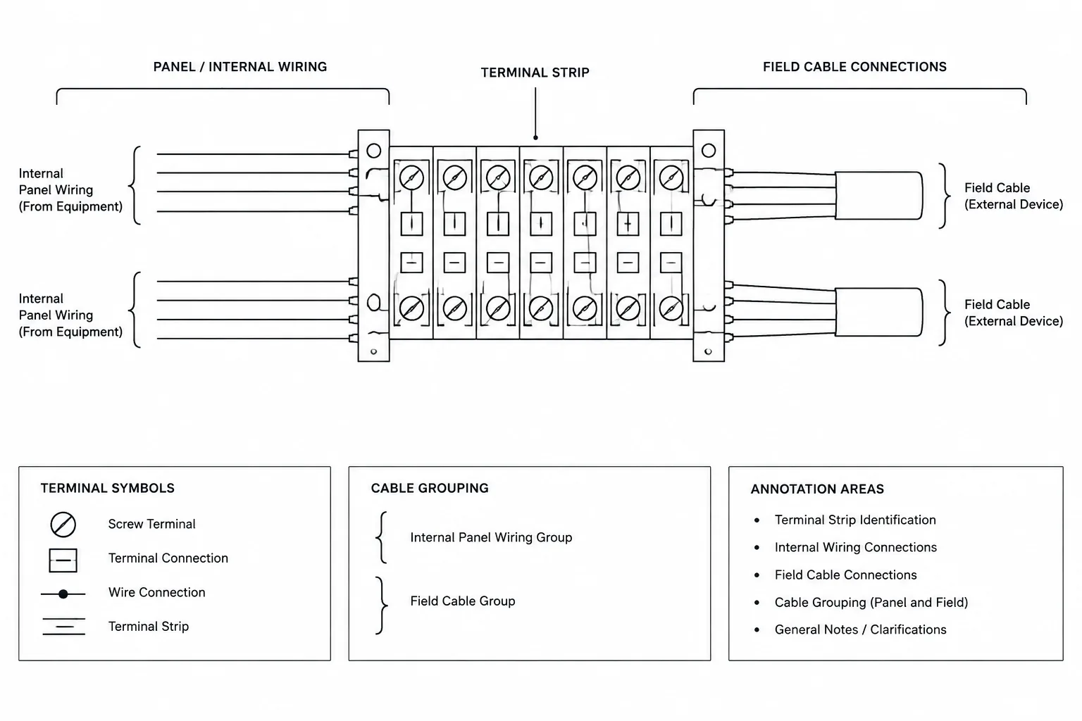
Terminal blocks sit at an important documentation boundary: they connect internal panel wiring to field cables, packaged equipment, sensors, controls, and other panels. If terminal information is scattered or inconsistent, even a clear schematic can become difficult to interpret. Well-organized terminal block drawings in CAD provide a common reference for designers, panel fabricators, installers, reviewers, and future maintenance teams.
A terminal drawing is not simply a row of generic rectangle symbols. It should communicate terminal identity, electrical relationship, physical grouping, cable association, and links to the rest of the drawing set. The exact format depends on the project, client requirements, and equipment involved, but the coordination principles remain similar.
What a terminal block drawing represents
A terminal block drawing documents connection points grouped into a strip, rail, enclosure, junction box, or equipment assembly. Depending on the project, terminal information may appear in several forms:
- Schematic representation: Terminals are shown within control or wiring circuits to indicate connection and disconnection points.
- Terminal strip diagram: Terminals are arranged in sequence with internal and external connection information.
- Panel layout: Terminal strips are shown in their approximate physical locations inside an enclosure.
- Connection schedule: Terminal data is presented in rows and columns for sorting, checking, or fabrication reference.
- Field interconnection diagram: Cables and conductors are shown traveling between panels, junction boxes, and field devices.
These views serve different purposes. A schematic explains circuit logic, while a panel layout addresses physical arrangement. A terminal diagram concentrates on connection identity. Trying to make one drawing perform every role often produces crowded graphics and duplicated data.
Establish a terminal identification structure
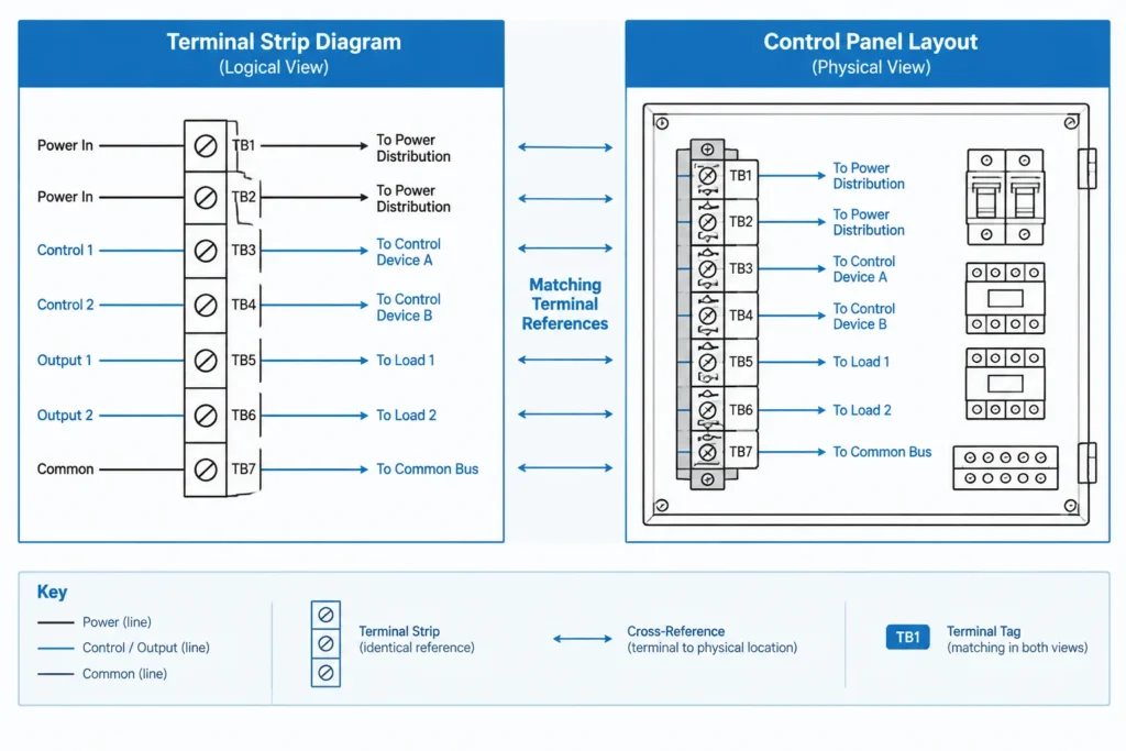
Before drafting symbols, define how terminal strips and individual terminals will be identified. A strip identifier should remain stable wherever it appears: schematic, layout, connection diagram, cable schedule, and terminal schedule. Individual terminal designations should follow the project’s approved naming convention rather than an improvised CAD sequence.
The identifier may need to communicate location, enclosure, function, or strip grouping. However, adding too much meaning can make tags long and difficult to maintain. Use the minimum structure necessary to produce an unambiguous reference, and document the convention in a legend or drafting note.
Spare and reserved terminals should also be identified consistently. A spare terminal is an installed connection point without an assigned circuit, while a reserved position may represent space or capacity planned for a defined purpose. The drawing should not treat these terms as interchangeable unless the project convention does.
Build a terminal symbol with useful CAD data
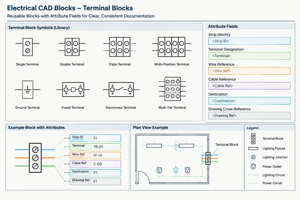
A reusable terminal block should have simple, legible geometry and controlled attributes. It does not need to imitate the manufacturer’s physical product in detail. The symbol’s primary job is to organize information and maintain alignment.
Useful block data may include:
- Terminal strip identifier
- Individual terminal designation
- Terminal type or function
- Internal wire reference
- External wire or cable-core reference
- Connected device or destination
- Schematic sheet and grid reference
- Panel, enclosure, or junction-box location
- Notes for spare, shield, grounding, disconnecting, or fused functions
Not every item belongs visibly beside the symbol. Some values may be stored as attributes for extraction into a schedule. Separate displayed text from data used only for reports so that drawings remain readable.
Use distinct graphics only when they carry meaning
Different terminal functions may require different symbols or annotations. Examples include disconnecting terminals, grounding terminals, shield termination points, fused terminals, and multi-level arrangements. Use graphical differences only when the project documentation needs that distinction. Decorative manufacturer-like geometry can create visual noise and may falsely imply a specific product.
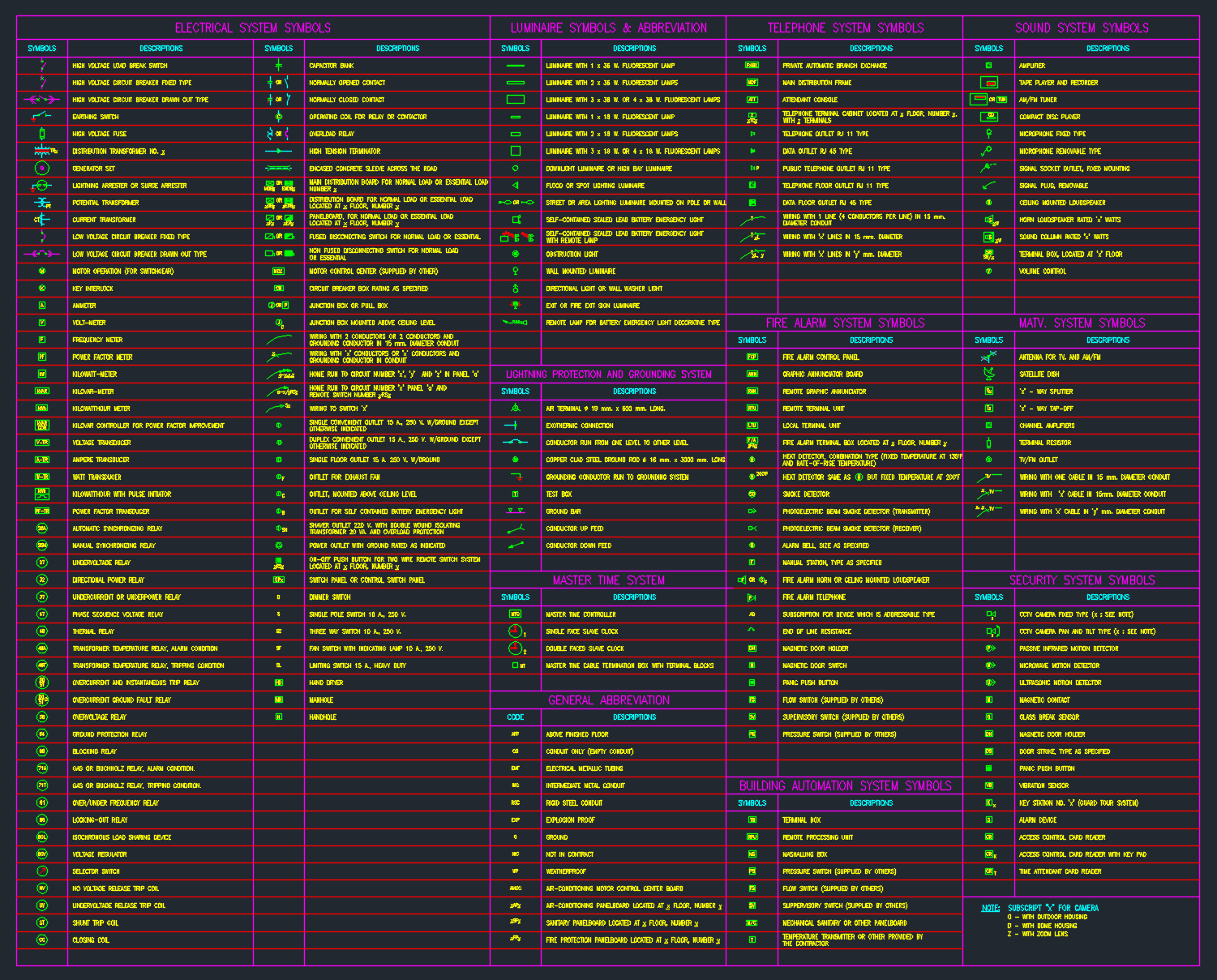
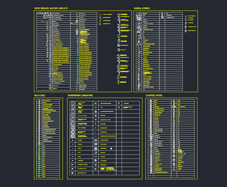
Maintain a generic CAD library for common documentation functions, then attach project-specific descriptions through attributes or schedules. Product selection and actual terminal compatibility must be verified separately against approved project information.
Organize the terminal strip diagram
A terminal strip diagram is easiest to review when information follows a predictable direction. Internal panel connections can be placed on one side and field or external connections on the other. Keep that orientation consistent across the set and state it in the legend if it is not visually obvious.
Arrange terminal entries in a sequence that supports the design intent. Possible organizing methods include circuit order, device grouping, cable grouping, signal type, or physical strip sequence. The selected method should match the purpose of the drawing. A fabrication-oriented terminal plan may prioritize physical order, while a design-oriented interconnection diagram may prioritize cable and destination relationships.
| Information | Typical drawing role | Coordination check |
|---|---|---|
| Strip and terminal identity | Locates the connection point | Matches every schematic and layout reference |
| Internal connection | Links the terminal to panel circuitry | Agrees with the control or wiring schematic |
| External connection | Identifies the field-side destination | Agrees with plans and equipment documentation |
| Cable and core data | Associates conductors with a cable | Matches the cable schedule |
| Terminal function | Distinguishes special connection types | Matches the selected equipment and design intent |
| Cross-reference | Directs readers to related drawings | Remains valid after sheet revisions |
Coordinate terminal data across drawing types
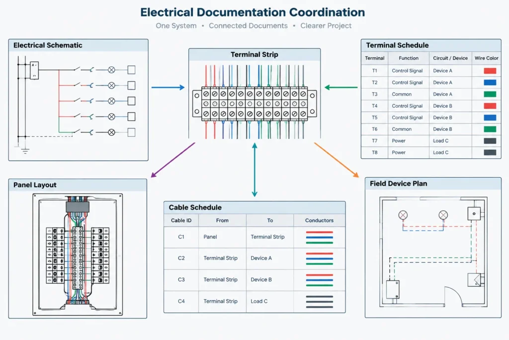
The most common terminal documentation problems are coordination problems rather than drafting problems. A terminal may appear correctly in one diagram but carry a different identifier elsewhere. Establish a defined source of truth for each data field.
- Schematics should establish the circuit relationship and connection logic.
- Panel layouts should establish the approximate physical location and grouping.
- Cable schedules should establish cable identity, origin, destination, and conductor allocation where applicable.
- Terminal schedules should compile connection data without silently changing the design shown elsewhere.
- Plans and equipment layouts should confirm that external devices and enclosures use matching tags.
When CAD attributes are extracted into schedules, avoid maintaining a separate manually typed copy of the same information unless the workflow includes a reliable comparison process. Duplicate data sources tend to drift apart during revisions.
Cross-reference without overloading the drawing
A terminal entry may need a sheet, detail, zone, or grid reference. Use the reference system already established for the drawing set. Cross-references should point readers toward the controlling circuit information rather than repeat the entire circuit description beside every terminal.
Automatic or data-driven references can reduce repetitive edits, but they still require review. Sheet reordering, copied blocks, and reused project templates can leave references that appear valid while pointing to outdated content.
Represent cables, shields, jumpers, and multi-level terminals clearly
Some connections need more than a basic terminal symbol. Cable boundaries can be shown with a bracket, outline, or grouped annotation so readers can see which conductors belong together. The chosen graphic should be explained in the legend and applied consistently.
Shield and drain connections require especially clear documentation. Show where the connection is intended to occur and avoid implying additional terminations through ambiguous linework. The drawing should document design intent, not substitute for verified equipment instructions or project requirements.
Jumpers should be visibly different from ordinary point-to-point conductors. Their extent must be clear so that a reader can identify every terminal included in the common connection. For multi-level terminals, indicate the level or connection position with a consistent attribute, suffix, or diagram arrangement. A flat symbol without level information can make separate connection points appear electrically common.
Use layers and annotation controls deliberately
Place terminal symbols, connecting lines, identifiers, cable annotations, cross-references, and revision graphics on suitable CAD layers. This allows the drawing team to control plotting, isolate information, and perform quality checks. Avoid putting all terminal content on one generic electrical layer if the project layer structure supports clearer separation.
Text should remain readable at the intended plotted scale. Attribute locations should be tested with realistic long tags and descriptions, not only short placeholders. If long values repeatedly collide, revise the block layout or move secondary information into a schedule rather than reducing text until it becomes difficult to read.
Practical terminal drawing workflow
- Collect controlling information. Review schematics, equipment tags, panel layouts, cable data, and approved connection requirements.
- Define the identification convention. Establish strip, terminal, enclosure, cable, and conductor references before populating drawings.
- Select the drawing purpose. Decide whether the sheet is a logical terminal diagram, a physical arrangement, a connection schedule, or a coordinated combination.
- Place data-enabled terminal symbols. Use approved blocks with consistent insertion points, attribute order, and text behavior.
- Group related connections. Organize by physical strip, circuit, device, or cable according to the documented project method.
- Add cross-references. Link terminal entries to the relevant schematic, layout, and cable information.
- Extract or update schedules. Generate tabular information from controlled CAD data where the workflow permits.
- Run coordination checks. Compare identifiers, destinations, cable references, special terminal functions, spares, and cross-references across the complete drawing set.
Quality-control questions before issue
- Does every terminal have an unambiguous identity?
- Do terminal strip tags match the panel layout and schematics?
- Are internal and external sides consistently oriented?
- Do cable and conductor references agree with the cable schedule?
- Are jumpers, shields, grounding connections, and special terminal functions distinguishable?
- Are multi-level connection points clearly identified?
- Do cross-references lead to current sheets and locations?
- Are spare and reserved positions described consistently?
- Can all annotations be read at the intended plotted scale?
- Have copied or mirrored blocks retained the correct attributes?
A drawing interface, not an isolated detail
A terminal block drawing should be treated as an interface between circuit logic, physical equipment, and field cabling. Its value comes from coordination rather than graphic complexity. Simple symbols, stable identifiers, controlled attributes, and clear cross-references usually produce a more useful document than a highly detailed product illustration.
Before using a CAD block or terminal diagram on a real project, verify its symbols, terminology, connection functions, and equipment assumptions against the project’s approved design information. A well-built CAD library can accelerate drafting, but project-specific engineering and documentation review remain essential.




Leave a Reply
You must be logged in to post a comment.