
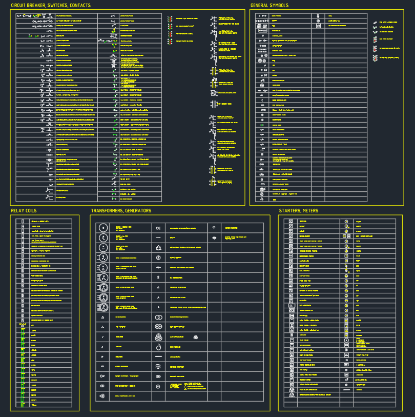
Schematic metering equipment symbols help electrical drafters represent measurement devices consistently in diagrams and project documentation. This DWG resource is intended for AutoCAD users who need editable CAD graphics for electrical and instrumentation drawings.
Use the file as a reference element within a broader drafting workflow that may also include electrical legends, single-line diagrams, panel documentation, lighting plans, power plans, and equipment layouts. Always review symbol usage against the conventions and documentation requirements established for the project.
Discover a comprehensive DWG file featuring Schematic Metering Equipment Symbols, ideal for electrical and instrumentation design projects. This CAD Block includes a wide range of standardized symbols, ensuring accurate representation of metering devices such as voltmeters, ammeters, and power meters in your schematic diagrams. Perfect for engineers, architects, and drafting professionals, these symbols streamline the design process and maintain industry compliance. Fully compatible with AutoCAD and other leading CAD software, this file enhances your workflow by providing easy-to-edit, scalable vector symbols suitable for any project requiring precise metering equipment schematics. Download now to elevate your CAD documentation.
Please log in or register to download this file.
About the schematic metering symbols
The drawing includes a range of schematic symbols for metering equipment, including voltmeters, ammeters, and power meters. These graphics can help communicate where measurement functions appear in an electrical or instrumentation schematic without redrawing each symbol manually.
How this DWG can support drafting
- Electrical schematics: Place metering symbols in diagrams that document measurement devices and their relationship to connected equipment.
- Instrumentation documentation: Use the symbols as editable drafting elements when preparing instrumentation-related drawings.
- Panel and distribution references: Coordinate metering graphics with panel schedules, distribution documentation, and electrical legends as applicable.
- CAD workflow: Edit, scale, arrange, and reuse the vector symbols within a compatible CAD environment while preserving a clear drawing hierarchy.
Drafting checks before issue
Confirm that each symbol matches the project legend and intended device. Check orientation, nearby labels, linework clarity, layer organization, and plotting behavior before issuing a drawing. Symbol appearance alone does not define wiring, ratings, installation requirements, or measurement performance; those details should come from the approved project documentation and equipment information.
Related electrical CAD references
Metering symbols are most useful when coordinated with single-line diagram concepts, schematic symbols, electrical legends, cable and conduit drafting, and panel documentation. Keeping these related drawing elements consistent improves readability across the electrical drawing set.
Frequently asked questions
What does this DWG resource contain?
It contains schematic metering equipment symbols for use in electrical and instrumentation design documentation, including voltmeter, ammeter, and power meter graphics.
Can the symbols be used in AutoCAD?
Yes. The source file is described as compatible with AutoCAD and other leading CAD software. Confirm compatibility and display behavior in the CAD application used for the project.
Are these symbols intended for construction without review?
No. They are drafting resources, not a substitute for an approved electrical design, project legend, equipment information, or engineering review. Verify the selected symbols and their use before issuing documentation.
Can the symbols be edited?
The file is described as containing easy-to-edit, scalable vector symbols. Users should still check layers, linework, labels, and plotting results after making changes.
Which drawings can use metering symbols?
They may support electrical schematics, instrumentation drawings, single-line diagram references, panel documentation, and related electrical CAD work when coordinated with the project’s drafting conventions.

Leave a Reply
You must be logged in to post a comment.