
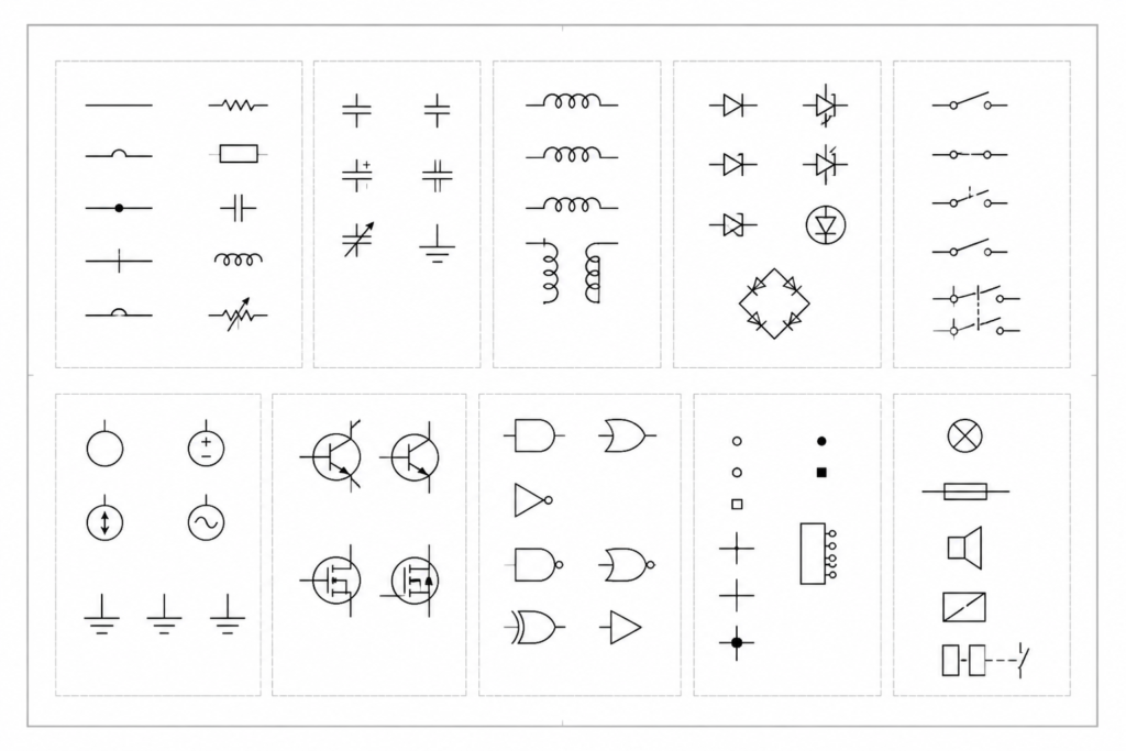
Schematic Miscellaneous Symbols DWG files help CAD users build clearer diagrams without redrawing commonly used graphic elements. This resource is intended for professionals working with electrical, architectural, and mechanical drawing documentation.
Use the downloadable DWG as a drafting reference when preparing schematics, circuit layouts, equipment documentation, and related CAD views. Before issuing a drawing, review each symbol against the project legend, office drafting practices, and the applicable design requirements.
Discover our comprehensive DWG file featuring Schematic Miscellaneous Symbols, perfectly designed for CAD professionals and engineers. This high-quality CAD Block includes a wide variety of essential schematic symbols commonly used in electrical, architectural, and mechanical drawings. Easily integrate these symbols into your AutoCAD projects to streamline your drafting process and ensure standardized documentation. Compatible with all major versions of AutoCAD, this DWG file is an invaluable resource for creating precise technical diagrams, circuit layouts, and professional schematics. Download now to enhance your design workflow with ready-to-use, editable schematic miscellaneous symbols.
Please log in or register to download this file.
What this schematic symbol DWG is used for
The file provides a collection of editable schematic miscellaneous symbols for use in AutoCAD projects. Rather than treating the block collection as a complete design system, use it as a practical starting point for assembling technical diagrams and maintaining consistent graphic communication.
Where miscellaneous symbols fit in a CAD workflow
- Electrical drawings: Add symbols to circuit layouts, equipment diagrams, panel documentation, and related schematic views.
- Architectural drawings: Support coordinated plans and details where technical symbols must remain legible beside building information.
- Mechanical drawings: Use appropriate graphic elements in equipment-related diagrams and documentation.
- CAD standards: Compare inserted symbols with the drawing legend, layer rules, text conventions, and document-specific requirements.
Practical drafting checks
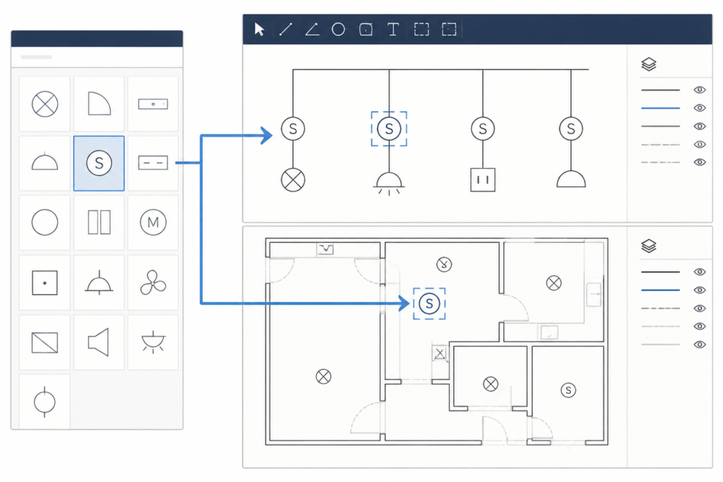
After inserting a symbol, confirm its orientation, visibility, layer assignment, insertion behavior, and relationship to nearby lines or annotations. Keep the drawing readable at its intended plotted scale and avoid using a symbol whose meaning is unclear in the project context.
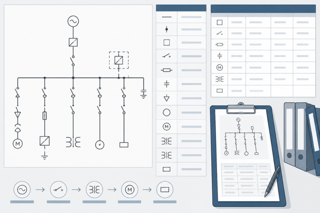
This resource also fits naturally with related CAD reference topics, including electrical legends, single-line diagram concepts, panel and distribution documentation, lighting and power plans, and cable and conduit drafting. Those topics help explain how individual symbols become part of a coordinated drawing set.
Download and use the editable resource
The source description identifies this DWG as compatible with major AutoCAD versions and suitable for integration into AutoCAD projects. Download the file, inspect its contents in your approved CAD environment, and adapt the symbols only as permitted by your project documentation and drafting standards.
Frequently asked questions
What is included in the Schematic Miscellaneous Symbols DWG?
The file contains a wide variety of schematic symbols commonly used in electrical, architectural, and mechanical drawings. Review the downloaded content to identify the symbols relevant to your project.
Can these symbols be used in AutoCAD drawings?
Yes. The source description presents the DWG as an editable CAD resource intended for AutoCAD projects and compatible with major AutoCAD versions.
Are these symbols a substitute for a project drawing legend?
No. A symbol library is a drafting resource, while the project legend and document requirements establish how symbols are interpreted and applied in a specific drawing set.
Should symbols be checked before a drawing is issued?
Yes. Check the symbol meaning, orientation, visibility, layer behavior, and coordination with nearby notes and linework. Electrical work should be designed, reviewed, and performed by qualified professionals; this CAD resource does not provide instructions for working on energized systems.












Leave a Reply
You must be logged in to post a comment.