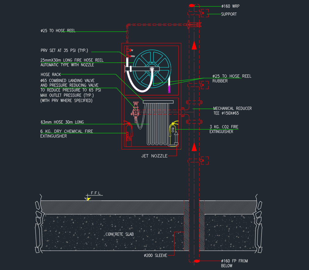
Fire hose cabinet details in AutoCAD help design teams document the cabinet location, wall relationship, access area, and coordination requirements within a building drawing set. A cabinet detail may support architectural, fire protection, and electrical coordination, but it should always be checked against the project specifications and approved equipment information.
The existing downloadable content is preserved below. Before placing the detail in a project, review its geometry, notes, dimensions, layers, and drawing units rather than treating it as a universal installation detail.
Discover comprehensive **Fire Hose Cabinet Details** with this high-quality DWG file and CAD Block, perfect for architects, engineers, and designers. The downloadable drawing provides precise and detailed views of fire hose cabinet assemblies, including dimensions, materials, and installation guidelines. Ideal for use in commercial, residential, and industrial building plans, this resource ensures code compliance and safety standards. Fully compatible with AutoCAD and other leading CAD software, this file streamlines your project workflow and guarantees professional results for fire protection system designs.
Please log in or register to download this file.
What a Fire Hose Cabinet Detail Should Communicate
A useful cabinet drawing normally shows more than the visible cabinet face. Depending on the source file, it may include plan, elevation, or section information that helps the drafter understand the cabinet enclosure, door swing, wall interface, and adjacent construction. Labels should make it clear whether the linework represents the cabinet body, opening, trim, equipment, or surrounding wall.

The detail should also be distinguishable from the simplified symbol used on a floor plan. A plan symbol identifies location, while an enlarged detail explains construction and coordination. The project legend, equipment schedule, and specification should use consistent terminology so reviewers can connect the symbol to the correct detail.
CAD Review Checklist
- Drawing units: Confirm that the imported geometry uses the same unit convention as the destination file.
- Scale and annotation: Check that text, dimensions, leaders, and symbols remain readable at the intended plotted scale.
- Layers: Move linework onto project-approved layers without losing the distinction between equipment, walls, hidden components, dimensions, and notes.
- Block structure: Inspect nested blocks, attributes, duplicate definitions, and unexplained objects before adding the content to a shared model.
- Line hierarchy: Use plotting conventions that clearly separate cut elements, visible outlines, concealed components, and annotation.
- References: Verify that no missing external references, fonts, images, or custom line types are required.
- Project applicability: Compare the detail with the selected cabinet type, approved product information, architectural wall assembly, and fire protection design.
Coordination With Electrical Drawings
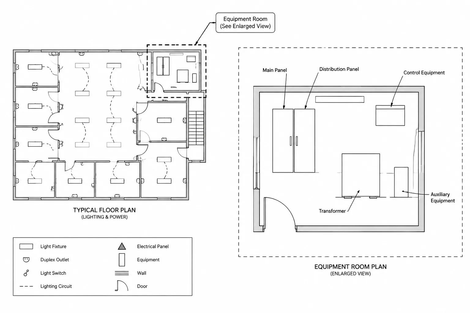
Although a fire hose cabinet is part of fire protection documentation, its placement can affect electrical plans. Review nearby panels, switches, receptacles, controls, raceways, and other wall-mounted equipment for physical or graphic conflicts. Door movement and access to adjacent equipment should remain understandable across the coordinated drawing set.
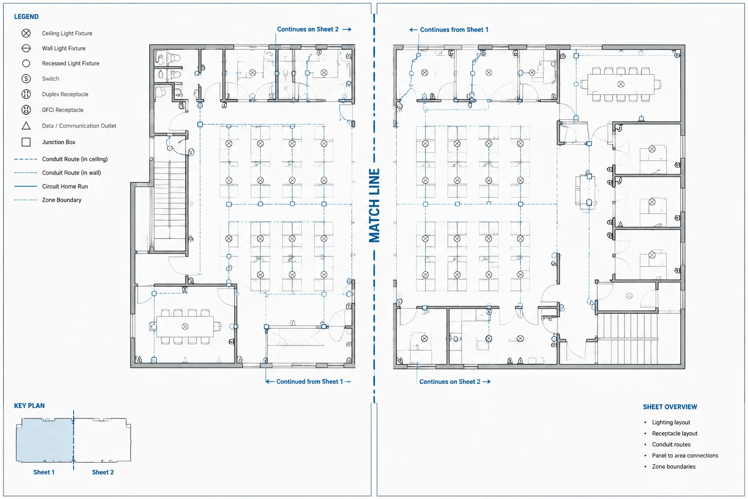
Coordination is especially important when separate disciplines use different background files. A cabinet shown only on a fire protection plan can be missed by an electrical drafter unless equipment locations are included in the shared architectural background or identified during coordination review.
Related Drawing References
This type of detail is most useful when read alongside fire protection symbols, equipment schedules, wall sections, life safety plans, electrical equipment layouts, and CAD layer standards. These related references help distinguish a location symbol from a construction detail and establish consistent labels across sheets.

Documentation and Approval
A generic CAD detail does not establish project compliance by itself. Final cabinet selection, placement, mounting conditions, notes, and dimensions should follow the approved design documents and applicable authority requirements. Where the source drawing conflicts with project-specific information, the verified project information should control.
Frequently Asked Questions
What views are useful in a fire hose cabinet drawing?
Plan, elevation, and section views serve different purposes. The plan can show location and projection, the elevation can show the visible cabinet arrangement, and the section can explain the relationship to the wall assembly. The views actually required depend on the project documentation.
Is a fire hose cabinet detail the same as a floor-plan symbol?
No. A floor-plan symbol is usually a simplified location marker. A detail provides additional information about the cabinet, surrounding construction, annotations, and coordination conditions.

Can the downloaded CAD block be inserted directly into a project?
It should be reviewed first. Confirm units, scale, layers, text styles, dimensions, block definitions, and compatibility with the selected equipment and wall construction. Remove irrelevant notes only after determining what they represent.
Why should electrical designers review this cabinet location?
The cabinet may share wall space with electrical devices, equipment, or raceway routes. Coordinated review helps prevent overlapping symbols, obstructed equipment, and inconsistent locations between discipline drawings.
Does a CAD detail prove code compliance?
No. A drawing file is a documentation resource, not an approval. Compliance depends on the complete project design, approved equipment, applicable requirements, and review by the responsible professionals and authorities.










Leave a Reply
You must be logged in to post a comment.