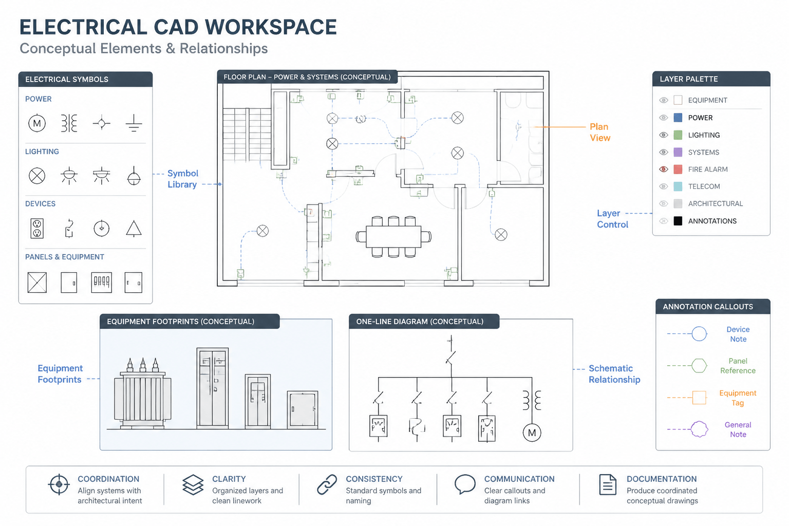
Using an electrical CAD block effectively requires more than selecting a recognizable symbol. The drafter must preserve what the object means, how it relates to surrounding graphics, and what another reader should understand from the completed view.
The following guidance focuses on that communication chain. It explains how block selection, placement, layer behavior, connections, annotation, and drawing context work together to preserve design intent without treating library content as verified project engineering.
Electrical CAD blocks can make a drawing faster to produce, but inserting a symbol or equipment footprint is not the same as completing the design. A block is a reusable graphic representation. Its meaning depends on the drawing type, project legend, layer structure, annotation, and the relationships shown around it.
This distinction matters when working with symbol libraries, equipment layouts, lighting plans, power plans, and single-line diagrams. A clean block may look correct in isolation yet communicate the wrong intent when its orientation, scale, connection points, or surrounding notes are unclear.
This guide explains a practical workflow for using electrical CAD blocks as controlled drawing content rather than decorative graphics. It is intended for conceptual drafting and drawing coordination, not as a substitute for project-specific engineering review.
What an electrical CAD block represents
An electrical CAD block may represent a device, connection point, equipment enclosure, schematic function, or annotation component. The same general object can appear differently depending on its drawing context.
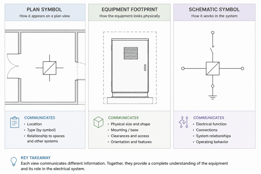
- Plan symbol: Shows the approximate location and graphical identity of a device in a floor or ceiling plan.
- Equipment footprint: Suggests the graphic extent and orientation of an enclosure, panel, cabinet, or other item in a layout.
- Schematic symbol: Communicates an electrical function or relationship without representing physical size or installation position.
- Detail component: Supports a section, elevation, mounting detail, or enlarged coordination view.
- Annotation block: Groups tags, identifiers, notes, or reference information into a reusable graphic.
These categories should not be mixed casually. A schematic symbol placed on a floor plan can be mistaken for a physical device, while a scaled equipment outline used in a single-line diagram can imply a level of physical information that the diagram does not provide.
Start with the drawing purpose
Before selecting a block, identify what the view is intended to communicate. Ask whether the drawing is showing location, function, routing, coordination, or documentation of an existing condition.
| Drawing context | Primary purpose | Block characteristics to check |
|---|---|---|
| Power or lighting plan | Show device locations and relationships to spaces or building elements | Plan orientation, insertion point, visibility at print scale, and connection graphics |
| Equipment layout | Coordinate the position and identification of physical equipment | Footprint representation, access zones shown by the project, orientation, and clearance annotations |
| Single-line or schematic diagram | Explain functional relationships and distribution paths | Symbol meaning, connection points, labels, and consistency with the project legend |
| Enlarged detail | Clarify a congested or technically important area | Annotation scale, reference tags, alignment, and consistency with related views |
A block should support the purpose of the view. It should not introduce physical assumptions into a schematic or hide important coordination information in a crowded plan.
Review a block before placing it
Do not judge a block only by its thumbnail. Open or inspect its geometry and determine how it behaves in the drawing environment. A short pre-placement review can prevent extensive cleanup later.
Check the insertion point
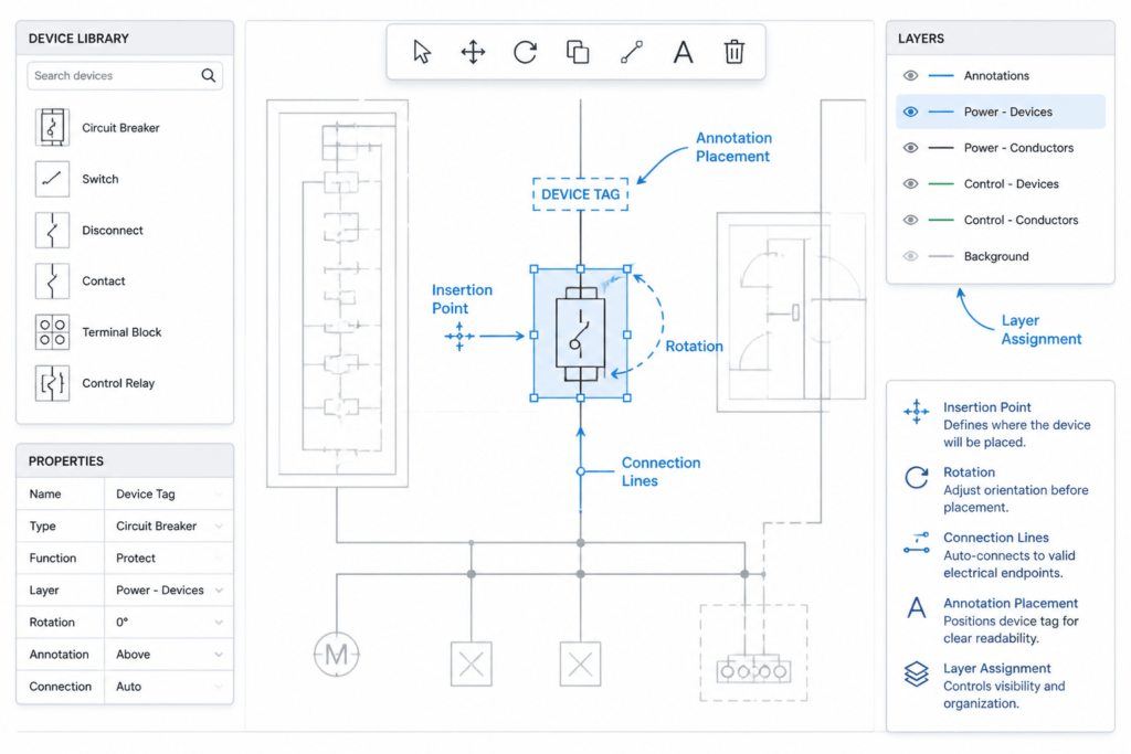
The insertion point controls how the block attaches to a wall, grid, centerline, equipment outline, or reference point. A block intended to align by its center behaves differently from one anchored at an edge or connection terminal. Inconsistent insertion points make repeated placement difficult and can create small alignment errors that are hard to see at normal zoom.
Check orientation and mirroring
Many electrical symbols have a meaningful orientation. A receptacle, switch, device connection, or equipment outline may need to face a particular wall, route, or access side. Mirroring can also change the apparent location of terminals or labels. Use rotation and mirroring deliberately, and confirm that the resulting graphic still matches the project legend.
Check scale behavior
A block can be created at an unsuitable unit scale or may have been designed for a different drawing environment. Compare it with nearby geometry rather than assuming that the displayed size is correct. For schematic symbols, visual consistency is usually more important than physical scale. For equipment layouts, the block should be treated as a representation that requires project-specific verification.
Check internal geometry
Look for duplicate lines, hidden objects, unexpected annotation, embedded hatches, or geometry on uncontrolled layers. These elements can affect plotting, selection, file size, and coordination. A block that contains unnecessary construction geometry may also obscure the information it is meant to show.
Match the block to the project graphic language
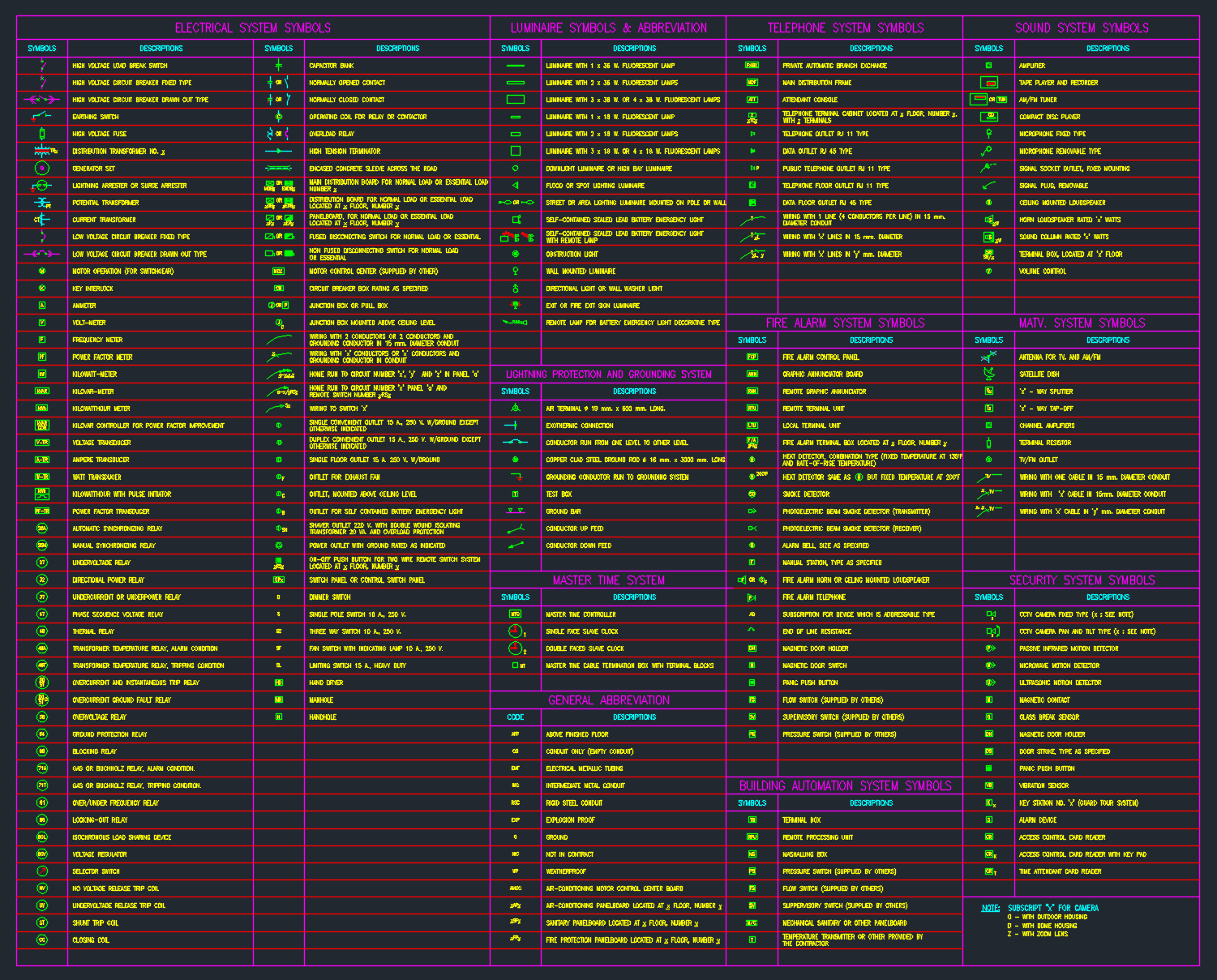
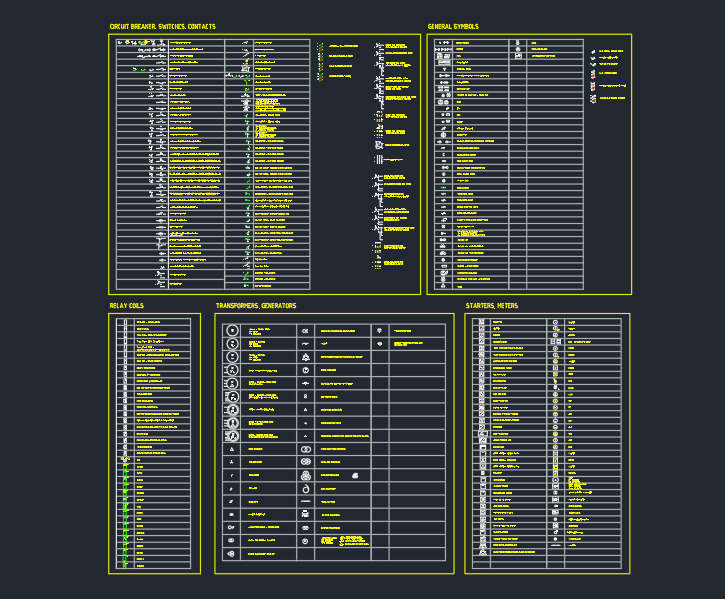
Electrical drawings are easier to read when symbols share a consistent visual language. This includes lineweight, text style, tag placement, circle or rectangle conventions, connection marks, and the treatment of equipment outlines.
A downloaded or legacy block may be technically recognizable but still conflict with the project’s established graphics. Before adding it to a production drawing, compare it with the project legend and nearby symbols. If the block uses a different style, consider whether it should be redrawn, simplified, or placed in a controlled library for later review.
Consistency does not mean that every symbol must look identical in every project. It means that the chosen graphic should have one understandable meaning within the drawing set.
Use layers to separate meaning from appearance
Layer control is especially important when blocks contain several graphic elements. A single inserted block may include symbol geometry, text, connection lines, or reference marks. If all of these elements land on one layer, it becomes harder to control visibility for different views.
When reviewing a block, determine which objects should inherit the insertion layer and which should retain dedicated layer assignments. A project may use separate layers for device symbols, equipment outlines, circuit graphics, annotations, or existing conditions. The exact naming convention should come from the project standard rather than being invented during insertion.
- Keep symbol geometry distinguishable from notes and tags.
- Avoid placing unrelated objects on a general-purpose layer merely to make the block display.
- Confirm that layer color and lineweight produce the intended plotted hierarchy.
- Test visibility in common drawing states, such as coordination, presentation, and issue views.
Connect blocks without implying more than the drawing shows
Connections are often where a block becomes misleading. A device symbol may need a circuit line, home-run indication, control relationship, or continuation reference. An equipment footprint may need an adjacent connection point or a separate note. These graphics should be coordinated with the drawing conventions rather than added automatically to every block.
Pay attention to whether a line terminates at the intended connection point. A line that merely touches the outside of a symbol may be visually ambiguous. Conversely, extending lines through a symbol can suggest an electrical relationship that is not intended. Use the project’s established convention for junctions, terminals, breaks, and continuation references.
Annotate after geometry is coordinated
Tags and notes should identify the block without covering its important geometry. Place annotation after the symbol has been oriented, aligned, and coordinated with nearby objects. This reduces the need to move labels repeatedly and helps keep the drawing readable.
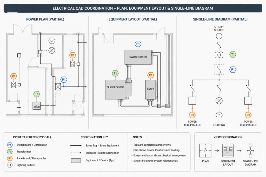
Where a block is used in multiple views, check whether the identifier, reference note, and related schedule or diagram use the same terminology. A symbol library can provide consistent graphics, but it cannot resolve inconsistent naming between plan views, schedules, details, and diagrams.
A practical CAD block audit
Before issuing or sharing a drawing, review inserted electrical CAD blocks using a repeatable checklist:
- Confirm that the block matches the purpose of the view.
- Verify insertion point, orientation, scale behavior, and mirroring.
- Compare the graphic with the project legend and nearby symbols.
- Inspect layers, lineweights, text, and hidden or duplicate geometry.
- Check connection lines and reference marks at normal print scale.
- Confirm that tags and notes are legible and use consistent terminology.
- Review the block in relation to architectural, mechanical, and structural backgrounds.
- Record any assumptions that require project-specific engineering or coordination review.
This process helps distinguish a useful CAD resource from an uncontrolled graphic. The goal is not simply to place more blocks; it is to make every block communicate one clear idea in the context of the drawing.
Use reference libraries responsibly
CAD libraries are valuable starting points for drafting, education, and coordination. They can reduce repetitive work and help users compare common symbol types. However, a library item should be treated as reference content until it has been reviewed against the project’s conventions and requirements.
Preserve the original source file when appropriate, but avoid allowing unreviewed blocks to define the project standard. Keep approved project content separate from exploratory or downloaded content, and document meaningful changes when a block is simplified or adapted.
Used this way, electrical CAD blocks become more than convenient shapes. They support a reliable visual vocabulary for plans, diagrams, details, and equipment layouts while leaving engineering decisions and project verification where they belong.
Preserve intent through the full drawing workflow
Design intent can be lost even when the selected block is graphically correct. A symbol may be placed accurately but assigned to an unsuitable layer, disconnected from its related graphics, labeled inconsistently, or shown in a view where its meaning is unclear. Review the block as part of the complete documentation system rather than as an isolated object.
Trace each block to a documented meaning
A reader should be able to connect the block with its legend entry, identifier, related notes, and any corresponding schedule or diagram. If those references use different names or graphics, the drawing set may appear to describe different devices or functions. Consistent terminology is therefore as important as consistent symbol geometry.
Distinguish graphic edits from design changes
Moving a label to improve readability is a graphic edit. Changing a symbol type, connection, orientation, equipment outline, or relationship may alter the apparent design intent. Treat those changes differently during review, and record assumptions when the drawing information does not establish the intended result.
Check the block in every relevant drawing state
A block that reads clearly in an active CAD workspace may become unclear when plotted, viewed against referenced backgrounds, or displayed with a different layer state. Inspect the result in the same conditions used for coordination and document issue. This helps identify masked connection lines, weak visual hierarchy, overlapping tags, and unintended objects before the drawing is shared.
Questions for final drawing review
- Does the block communicate location, function, physical extent, or annotation as intended by the view?
- Can a reader identify its meaning from the legend and surrounding documentation?
- Are connections deliberate and visually unambiguous?
- Do layers and lineweights support the required drawing hierarchy?
- Are labels coordinated with related plans, details, schedules, and diagrams?
- Would rotation, mirroring, or background changes alter how the block is interpreted?
- Are project assumptions clearly separated from verified information?
This review keeps reusable graphics efficient without allowing convenience to replace documentation judgment. The block remains a drafting tool, while its project meaning comes from coordinated drawing information and appropriate professional review.
Frequently asked questions
Can the same electrical CAD block be used in a plan and a schematic?
Only when the graphic clearly supports both contexts and remains consistent with the project legend. Plans generally communicate location and spatial relationships, while schematics communicate function and connectivity. Separate blocks are often clearer when those purposes differ.
Should a downloaded block be inserted directly into a project drawing?
It should be inspected before production use. Review its units, insertion point, orientation, internal layers, text, linework, attributes, and connection geometry. Keep unreviewed reference content separate from the approved project library.
Does a CAD equipment footprint confirm the actual equipment size?
No. A footprint is a graphical representation unless its geometry has been verified against project-specific information. Avoid treating an unverified library block as evidence of physical dimensions, access needs, or connection locations.
Why can mirroring an electrical block create confusion?
Mirroring may move terminals, access sides, labels, or connection points to a different apparent position. It can also make the result inconsistent with the legend. Review both the geometry and its meaning after mirroring.
What should remain consistent when a block appears in multiple views?
The identifier, terminology, symbol meaning, and documented relationships should agree across plans, diagrams, details, and schedules. The graphic representation may change with the purpose of each view, but the referenced item should remain clear.
How can a drafter tell whether a block edit affects design intent?
Consider whether the edit changes what the reader would infer about the device, function, connection, orientation, location, or physical extent. If it does, the change should receive project-specific coordination or engineering review rather than being treated as simple graphic cleanup.


Leave a Reply
You must be logged in to post a comment.