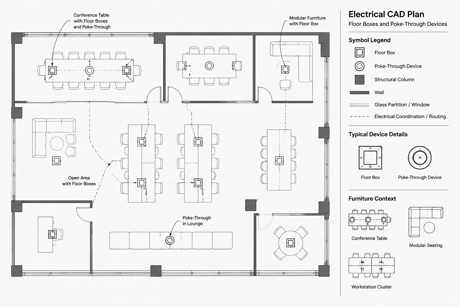
Drafting floor boxes and poke-through devices requires more than placing outlet symbols on a power plan. Each device must remain coordinated with furniture, architectural features, structural conditions, service pathways, and the drawings maintained by other disciplines.
This guide explains how to draft electrical floor boxes in CAD as traceable documentation elements. The emphasis is on symbol design, reliable location references, schedule coordination, drawing hierarchy, and quality control rather than product-specific installation requirements.
Floor boxes and poke-through devices can appear simple on an electrical plan, but their locations often affect several disciplines. A single symbol may represent power receptacles, communications outlets, furniture feeds, covers, internal dividers, conduit pathways, and a penetration through the floor assembly. If the drawing shows only a generic block without explaining these relationships, coordination problems can remain hidden until construction documentation is reviewed.
A useful electrical floor box plan should communicate more than device quantity. It should identify the device type, establish its location, show the intended services, and connect the plan symbol to schedules, details, and related drawings. The drafting workflow must also distinguish design intent from product-specific construction information that still requires verification.
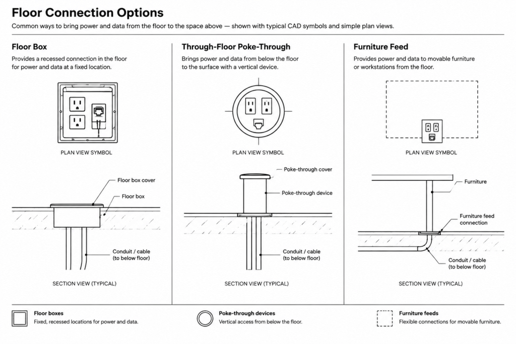
Floor Box, Poke-Through, and Furniture Feed Terminology
Before building CAD symbols, define how the project uses each term. Naming conventions vary among manufacturers, design teams, and project specifications.
- Floor box: A box or enclosure coordinated with the floor construction and used to provide power, communications, controls, or other services at the floor surface.
- Poke-through device: A through-floor assembly that routes services through an opening in the floor. Its documentation may require coordination with structural, architectural, fire-resistance, and installation information.
- Furniture feed: A connection point intended to supply modular furniture, workstations, casework, or another furniture system. It may provide power, communications pathways, or both.
- Trench or underfloor distribution system: A pathway system serving multiple floor outlets or connection points. It generally requires broader plan coordination than an isolated box.
These terms should not be treated as interchangeable unless the project documents specifically define them that way. A generic floor device symbol may be acceptable during an early layout, but later drawing stages usually need a clearer type designation.
Start with the Architectural and Furniture Backgrounds
Floor device placement is closely tied to architectural planning. Begin with the current architectural floor plan, reflected ceiling information where relevant, finish plans, enlarged plans, and furniture or equipment layouts. Confirm that the CAD backgrounds use a common coordinate system and represent the same design revision.
Important reference elements may include:
- Walls, doors, glazing, and fixed partitions
- Furniture systems and workstation clusters
- Conference tables, reception desks, and built-in casework
- Floor finish boundaries and access-floor areas
- Structural columns, beams, slab edges, and openings
- Equipment footprints and maintenance zones
- Room names, numbers, and tenant boundaries
A device centered under a conference table on one background may conflict with a table base or structural element on another. Keep architectural and furniture geometry as external references or other controlled background files rather than copying it into the electrical model. This makes revisions easier to identify and reduces duplicated geometry.
Build Symbols Around Documentation Needs
A floor device block should remain readable at the intended plot scale while carrying enough information to support coordination. Avoid drawing every internal component inside a small plan symbol. Detailed configuration belongs in a schedule, enlarged plan, or detail.
Recommended block components
- A clear plan symbol with a consistent insertion point
- A visible type tag or device identifier
- An orientation indicator when cover or service orientation matters
- Optional connection points for circuiting or pathway graphics
- Attributes for schedule-related information when the CAD workflow supports them
Place the insertion point at the actual location used for dimensioning, such as the documented device center or another defined reference point. The insertion point should not be based on decorative geometry that may change between block versions.
If multiple device families look similar, distinguish them with tags rather than minor graphic differences that disappear when plotted. For example, separate identifiers can differentiate a power-only floor box, a combined-services device, and a furniture-feed connection without overcrowding the plan.
Establish a Repeatable Location Method
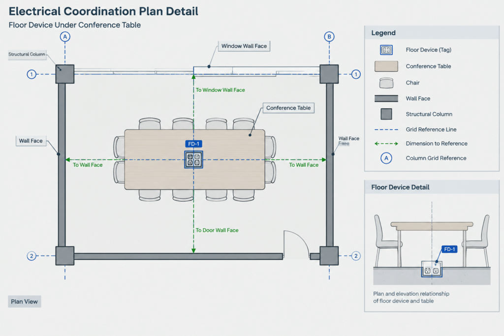
Floor devices often require more precise location information than wall-mounted devices. Do not rely only on visual centering unless the intended centerline is clearly established by permanent construction.
Common drawing references include structural grids, finished wall faces, column centerlines, fixed casework, and explicitly dimensioned architectural elements. Furniture can help explain design intent, but movable furniture may not provide a reliable construction reference. When a device is positioned for a table or workstation, coordinate the location with both the furniture plan and stable building geometry.
Use a consistent dimension origin across the floor plan and related enlarged plan. Conflicting dimensions from unrelated walls can make the location difficult to interpret after layout changes. Where electrical drawings do not carry installation dimensions, provide a clear note directing the reader to the controlling coordinated plan rather than adding approximate dimensions.
Coordinate Power, Data, and Pathways
A combined-services floor device may involve electrical power, communications cabling, audiovisual systems, security, controls, or pathways reserved for another discipline. The plan should make responsibility visible without implying details that have not been designed.
| Information | Typical drawing location | Coordination purpose |
|---|---|---|
| Device position and type | Electrical power plan | Defines the planned floor location and electrical category |
| Circuit or source reference | Power plan and panel documentation | Connects the device to distribution records |
| Communications outlet intent | Technology plan or coordinated electrical plan | Identifies data or communications service requirements |
| Internal device configuration | Schedule, detail, or specification reference | Clarifies service arrangement without crowding the plan |
| Pathway approach | Plan, enlarged plan, or section | Shows how conduits or cable pathways reach the device |
| Floor assembly relationship | Architectural section or coordinated detail | Supports slab, finish, cover, and penetration review |
When separate disciplines use their own symbols at the same location, avoid stacking unrelated blocks so precisely that one hides another. A coordinated composite symbol, shared tag, or agreed offset can improve readability. The legend should explain the chosen convention.
Use Enlarged Plans and Details Selectively
An enlarged plan is helpful where several floor devices serve dense furniture, equipment, or casework layouts. It can show orientation, service separation, pathway approaches, and nearby obstructions more clearly than a general floor plan.
A drafting detail may illustrate the documentation concept for a floor box or through-floor assembly, but it should not present an unverified generic block as a complete installation solution. Product geometry, floor construction, cover selection, fire-resistance considerations, accessibility, and finish interfaces must be confirmed from the project requirements and approved technical information.
Use sections when the vertical relationship matters. A section can clarify which floor level a device serves, whether pathways approach from above or below, and how the symbol relates to ceilings or occupied spaces beneath the slab. Keep schematic pathway graphics visually distinct from exact fabrication geometry.
Create a Floor Device Schedule
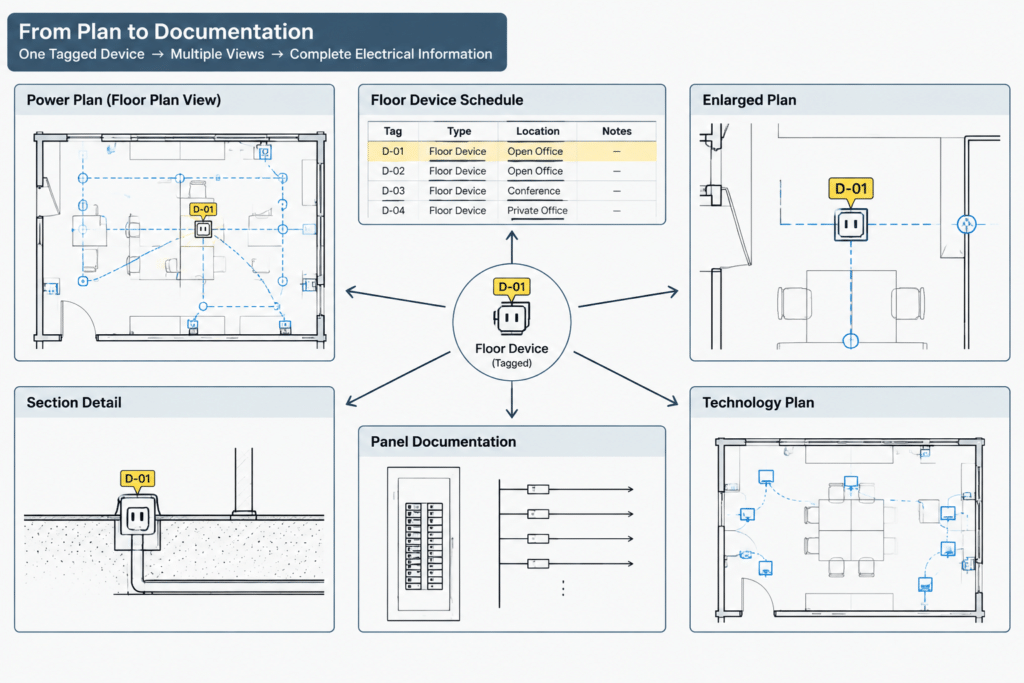
A schedule reduces repeated notes and provides a controlled place for configuration information. Useful fields may include the device type, service description, cover or finish designation, power configuration reference, communications provision, furniture association, detail reference, and remarks.
Only include fields that the project team can maintain. Empty or speculative schedule columns create the appearance of coordination without providing reliable information. Product-specific descriptions should match verified project documentation rather than assumptions embedded in a downloaded CAD block.
Where block attributes populate a schedule, standardize attribute names and allowed entries. A type tag shown on the plan should match the same type identifier in the schedule. Avoid manually typed tags placed over anonymous blocks because they are easy to separate during revisions.
Layer and Graphic Organization
Separate floor device symbols, tags, circuiting, pathways, dimensions, and notes according to the project CAD standard. This allows each information group to be controlled independently during plotting and coordination.
Use stronger graphics for the device itself and lighter graphics for circuit or pathway information. Architectural and furniture backgrounds should remain visually subordinate. If a device is shown only for coordination and belongs to another discipline, use a distinct layer and legend convention rather than making it appear to be part of the electrical scope.
Quality-Control Checks Before Issue
- Confirm every floor device tag appears in the applicable schedule or legend.
- Compare locations against the latest furniture, architectural, and equipment layouts.
- Review structural backgrounds for columns, framing, slab edges, and planned openings.
- Check that power, communications, and control drawings reference the same device locations.
- Verify that circuit and source references agree with panel and distribution documentation.
- Confirm that enlarged plans do not conflict with the general floor plan.
- Look for duplicate blocks, hidden symbols, disconnected tags, and obsolete device types.
- Plot the sheet to verify that symbols, dimensions, and service indicators remain readable.
- Flag product-dependent details and dimensions for verification rather than treating generic CAD geometry as approved construction information.
A Coordinated Symbol Is More Valuable Than a Detailed Symbol
The best electrical floor box plan is not necessarily the one with the most elaborate blocks. It is the one that lets a reader locate each device, understand its purpose, identify its services, and find the related schedule or detail without guessing.
Use CAD blocks as consistent information carriers, not as substitutes for design verification. When symbols, tags, schedules, backgrounds, and cross-discipline drawings are maintained together, floor devices become easier to coordinate and far less likely to be overlooked during drawing review.
Maintain a Clear Documentation Hierarchy
A coordinated floor device should have one primary plan location and a consistent identity wherever it appears. The general plan establishes the device position and type, while schedules, enlarged plans, sections, and details add information that would make the main plan difficult to read. Repeating complete configuration data in several places increases the risk that revisions will leave conflicting instructions.
Define which drawing controls each category of information. For example, the electrical plan may control the power designation, a technology drawing may describe communications intent, and a coordinated detail may explain the relationship to the floor assembly. Cross-references should lead the reader between these documents without suggesting that an illustrative CAD block contains verified product geometry.
Manage Revisions as Coordinated Changes
When furniture, partitions, equipment, or structural backgrounds move, review the associated floor devices rather than shifting symbols automatically. A revised location may affect dimensions, circuit graphics, pathway routing, tags, schedules, detail references, and drawings issued by another discipline.
Use stable block identifiers and controlled attributes so a device can be tracked through these changes. Before issue, compare the current plan against the controlling backgrounds and investigate unexplained duplicate or abandoned symbols. This approach preserves design intent while making unresolved coordination items visible to the project team.
Know What the CAD Symbol Does Not Confirm
A plan symbol communicates documentation intent; it does not by itself confirm compatibility with the floor assembly, cover, internal service arrangement, furniture system, pathway approach, or penetration requirements. Those conditions depend on verified project information and coordinated technical documentation.
Keep generic graphics appropriately schematic, and flag product-dependent information for review. A simple symbol with a reliable tag and cross-reference is generally more useful than detailed geometry that has not been validated for the project.
Frequently Asked Questions
What should an electrical floor box CAD block contain?
It should contain a readable plan symbol, a defined insertion point, a device identifier, and an orientation indicator when orientation affects coordination. Attributes may carry schedule-related information, but detailed internal arrangements are usually clearer in a schedule or detail.
How is a poke-through device different from a floor box on a drawing?
A floor box generally identifies a service point coordinated with the floor construction. A poke-through designation also communicates that services pass through the floor assembly, which can require additional structural, architectural, pathway, and penetration coordination. Project terminology should control the final labels.
Should floor devices be located from furniture?
Furniture is useful for showing design intent, especially at tables and workstation groups, but movable furniture may not be a dependable construction reference. Where precise placement is required, coordinate the device with stable building geometry and the controlling project plan.
When should an enlarged floor device plan be used?
An enlarged plan is helpful when device orientation, dense furniture, nearby casework, multiple services, or pathway approaches cannot be communicated clearly on the general plan. It should agree with the general plan and use matching device identifiers.
Can power and communications symbols occupy the same CAD location?
They can represent services within the same coordinated device, but directly stacked symbols may hide information. A composite symbol, shared identifier, or documented graphic offset can improve readability while preserving each discipline’s responsibility.
Why should product detail be limited in a generic CAD block?
Generic geometry may not match the selected device, floor construction, cover, service configuration, or project requirements. Use the block to communicate location and design intent, then rely on verified project documentation for product-dependent information.


Leave a Reply
You must be logged in to post a comment.