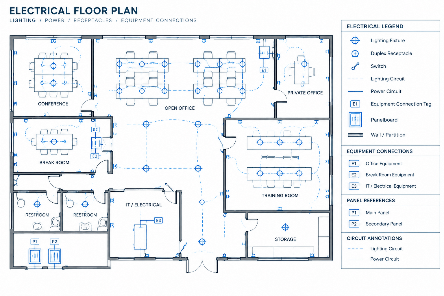
A receptacle and small-power plan documents where electrical outlets, connection points, and related devices are required within a building. Although the symbols may appear simple, the drawing must coordinate architectural use, equipment needs, circuit information, mounting conditions, and other building systems.
The goal is not merely to place outlet symbols around a floor plan. A useful receptacle and small-power plan communicates design intent clearly enough for review, coordination, estimating, and construction documentation. The drafter must also preserve consistency between plans, schedules, diagrams, details, and equipment information.
What belongs on a small-power plan?
The exact drawing scope varies by project, but a small-power plan commonly includes general-use receptacles, dedicated equipment outlets, floor outlets, service outlets, specialty receptacles, and identified connection points for fixed equipment. It may also show disconnect references, junction boxes, control power locations, and home-run or circuit annotations when these are part of the project documentation method.
Some project teams combine receptacles with lighting or equipment plans. Others use a separate power plan to reduce congestion. The decision should be based on drawing readability, project size, and the amount of information that must be coordinated—not simply on whether everything can fit into one CAD file.
Begin with coordinated background information
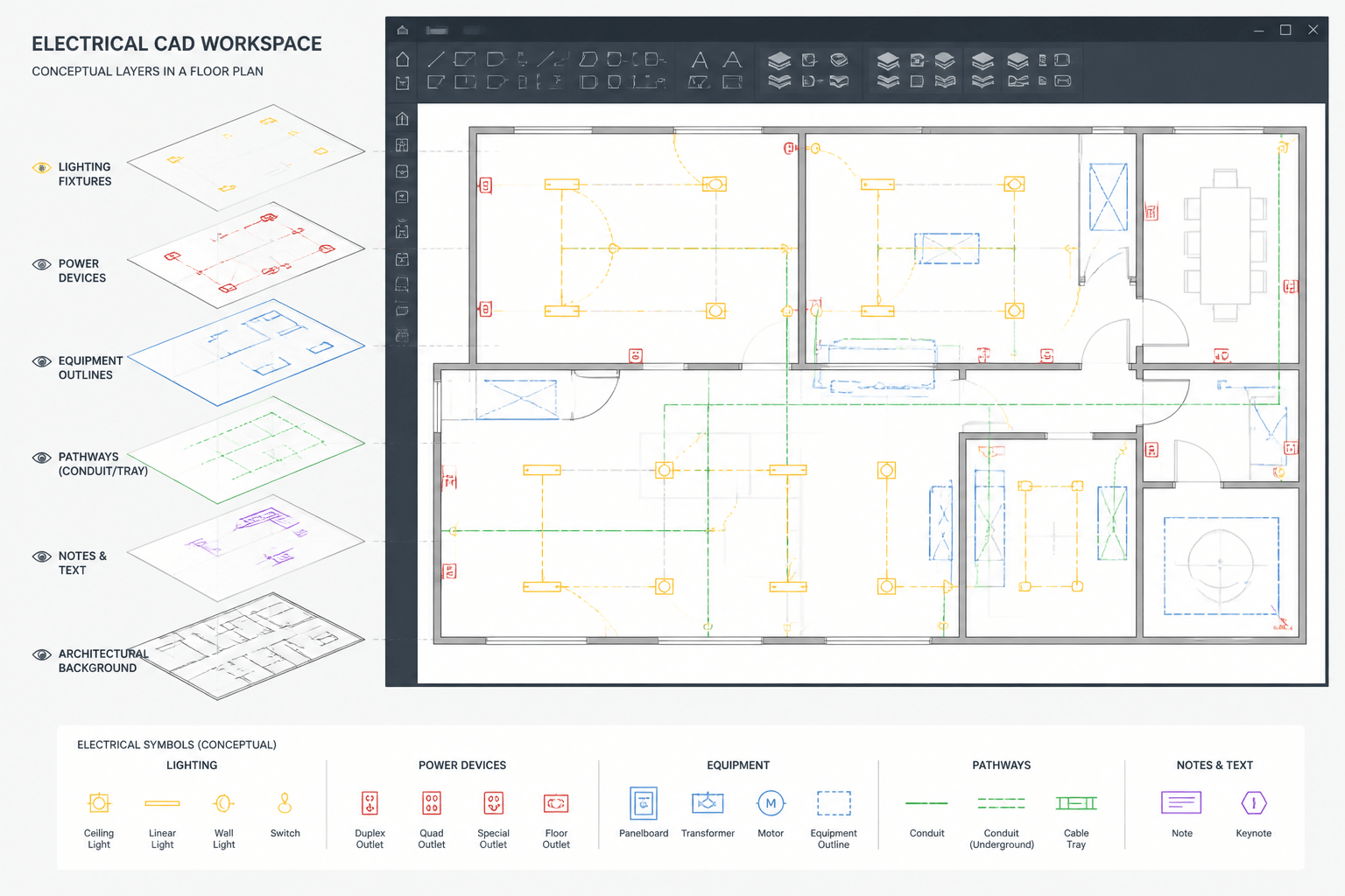
Use the current architectural background before placing electrical symbols. Room arrangements, doors, casework, furniture, equipment, partitions, and finish conditions can all affect device placement. A receptacle that appears reasonable beside an empty wall may conflict with cabinetry, glazing, movable partitions, or a door swing after the background is updated.
Useful design inputs may include:
- Architectural floor plans and enlarged room plans
- Furniture and casework layouts
- Equipment plans and connection schedules
- Interior elevations for counters, workstations, and wall-mounted equipment
- Mechanical, plumbing, fire protection, and low-voltage backgrounds
- Owner or tenant requirements
- Panel schedules and distribution diagrams
- Project-specific criteria and applicable code review comments
External references are generally preferable to copying background geometry into the electrical drawing. Referenced files allow architectural changes to appear without creating multiple uncontrolled copies. Background visibility should be adjusted so electrical information remains visually dominant when plotted.
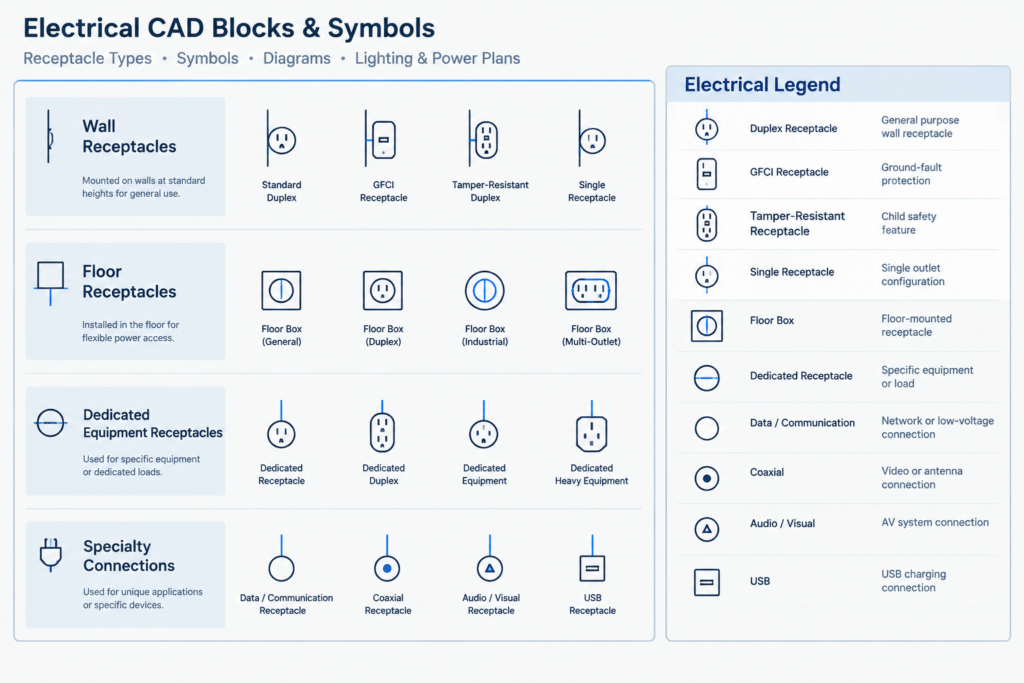
Build a consistent symbol vocabulary
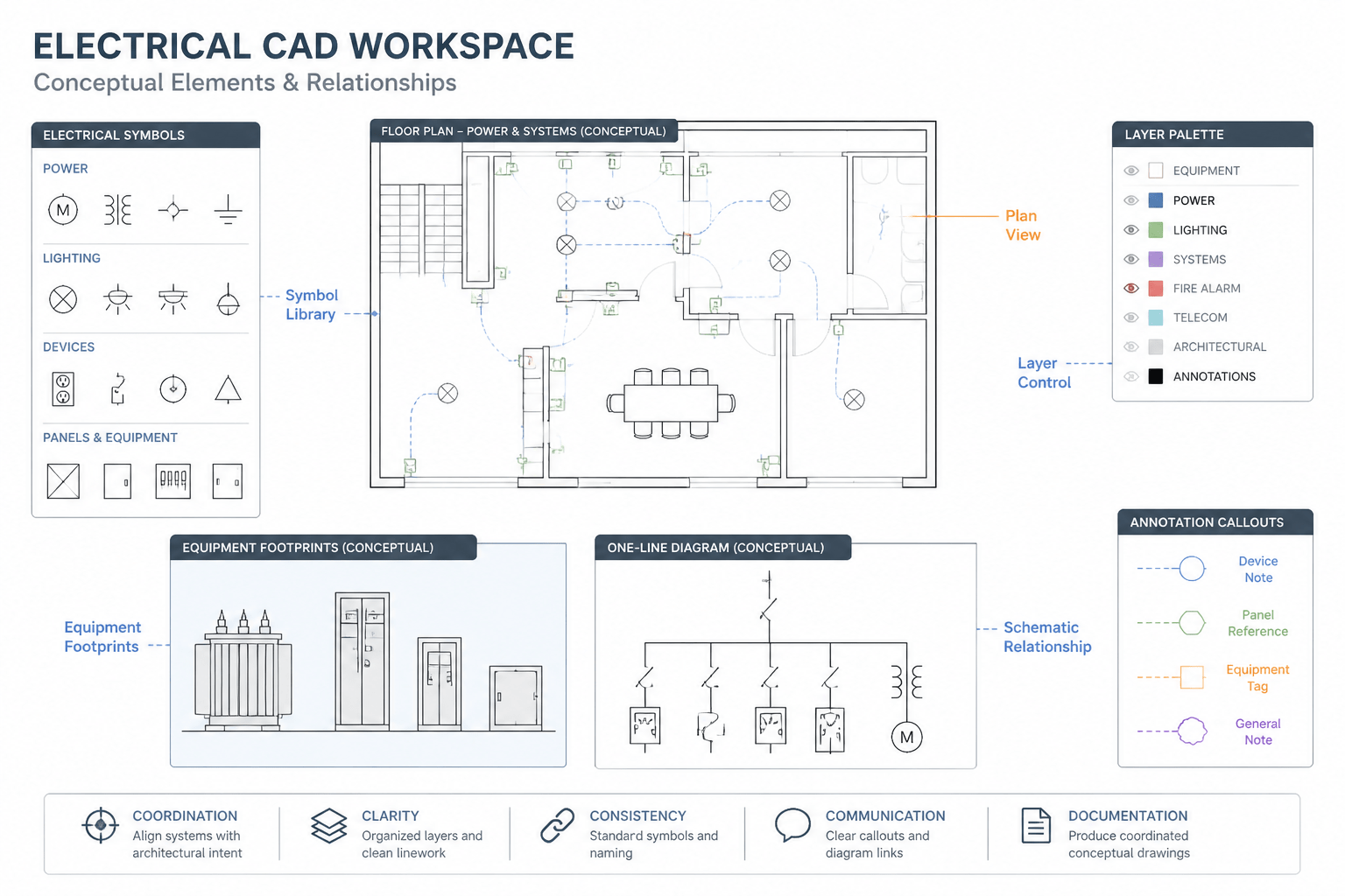
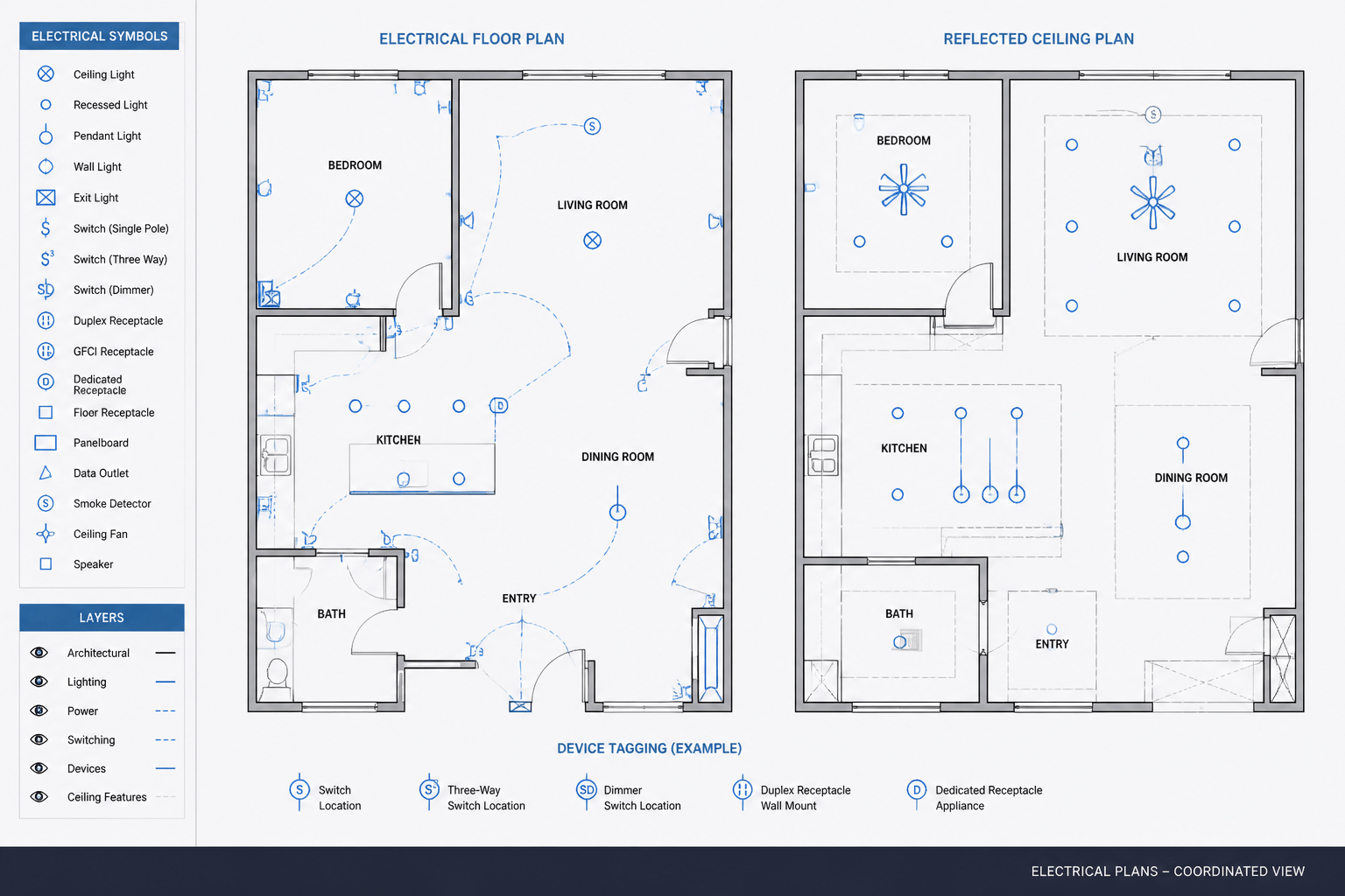
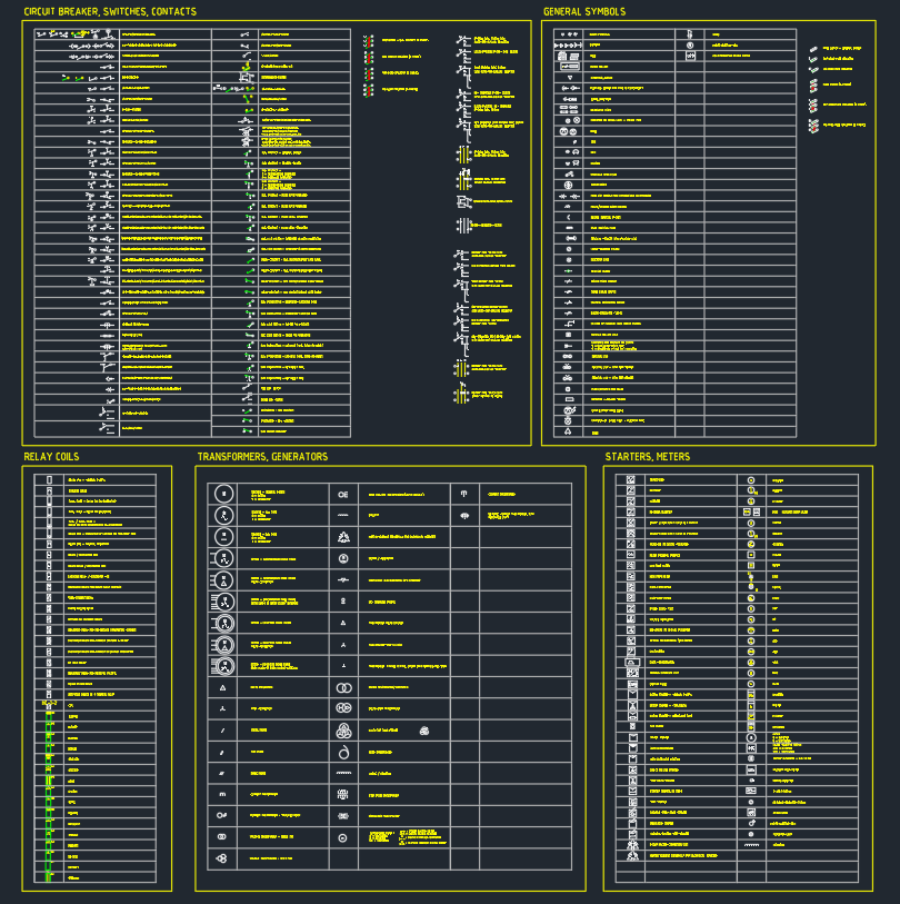
Each symbol should represent a defined device or connection condition. Avoid creating visually similar symbols whose differences are too subtle to survive printing, reduction, or PDF review. If two devices have different requirements, distinguish them through a clear graphic feature, an adjacent tag, or both.
| Information category | Typical documentation method | Coordination purpose |
|---|---|---|
| Device type | Distinct plan symbol | Identifies the general outlet or connection category |
| Special function | Symbol modifier or short tag | Separates general-use devices from dedicated or specialty conditions |
| Circuit source | Panel and circuit annotation | Connects the plan device to distribution documentation |
| Mounting condition | Note, elevation reference, or schedule entry | Clarifies conditions not visible in plan view |
| Equipment served | Equipment tag or keyed note | Links the electrical point to a coordinated load |
CAD blocks should have logical insertion points and predictable orientation. For a wall device, the insertion point might align with the intended wall location. A floor device may use its center. Whichever convention is selected, apply it consistently so symbols can be moved, counted, or reviewed without ambiguous offsets.
Use attributes selectively
Block attributes can store circuit identifiers, equipment tags, device comments, or other structured information. Attributes are valuable when they support schedules, extraction, or quality-control searches. They are less useful when every symbol accumulates hidden fields that no one maintains.
Decide which information belongs inside the block and which belongs in nearby annotation. Frequently changing text may be easier to manage as a consistent label, while stable identity fields may work well as block attributes. Test attribute visibility at the intended plot scale before using the block throughout a project.
Place devices according to design intent
Device placement should respond to the use of the space rather than follow a purely graphic pattern. Review each room for furniture, equipment, service needs, accessibility considerations, and unusual construction conditions. Do not infer unverified installation requirements from a generic CAD block.
Common conditions requiring additional coordination include:
- Outlets associated with workstations or systems furniture
- Devices above counters, within casework, or on millwork panels
- Floor outlets serving open spaces
- Connections for appliances and fixed equipment
- Exterior or wet-location conditions
- Devices near operable partitions, glazing, or architectural panels
- Maintenance and service outlets associated with building equipment
- Outlet assemblies containing power and communications services
Symbols should be legible without pretending to show the physical faceplate at full scale. Electrical plans are diagrams overlaid on building geometry, so slight graphic displacement may be necessary. If a symbol is offset from its actual location for clarity, use a leader, extension, or note that prevents misinterpretation.
Document dedicated and equipment connections carefully
A general-use receptacle and an equipment-specific connection may look similar on the plan while carrying very different design implications. Dedicated devices should be linked to the equipment they serve through an equipment tag, connection identifier, keynote, or schedule reference.
Verify the documented connection type against approved project information. Equipment may require a receptacle, junction box, direct connection, disconnecting means, or another interface. The CAD symbol alone should not be treated as proof of the final connection method.
When equipment data is incomplete, identify the item as requiring confirmation rather than inventing a rating or connection requirement. Maintain an open-items list so placeholders do not silently become issued design information.
Show circuiting without overwhelming the plan
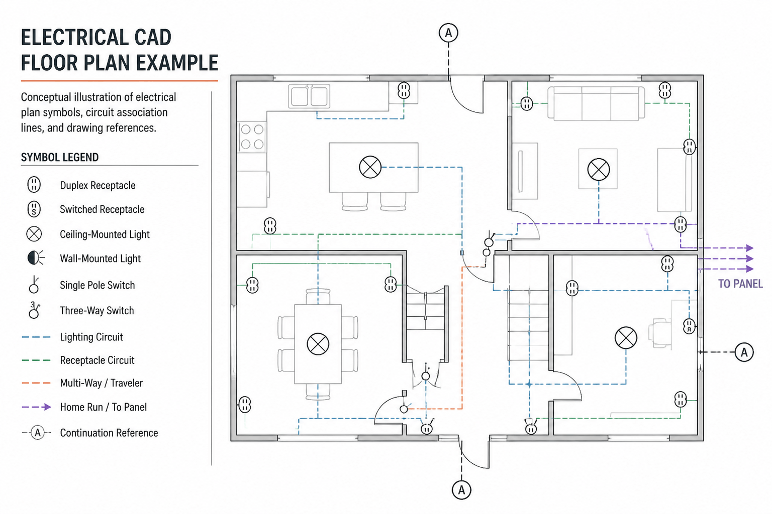
Circuit documentation methods differ among firms and projects. Some plans show branch-circuit lines between devices, while others rely primarily on panel and circuit tags. A hybrid method may show grouping or home-run intent without drawing every segment.
Whichever approach is used, the plan should make the source of each circuit understandable. Circuit lines should not be confused with walls, communication cabling, conduit routes, or control wiring. Use the project layer, linetype, and annotation conventions consistently.
Avoid long circuit lines crossing unrelated rooms when a continuation reference or localized annotation would be clearer. Circuit graphics should explain electrical relationships, not imply a precise raceway route unless the drawing is specifically intended to document routing.
Coordinate panel schedules and distribution drawings
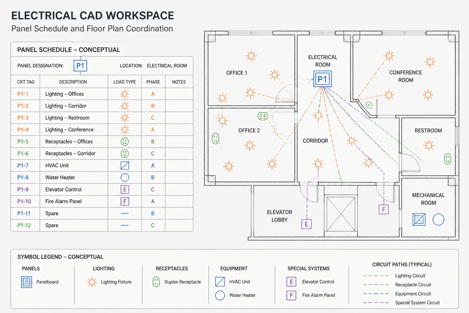
Every panel and circuit identifier shown on the plan should match the panel schedules or other circuit records. Coordination is especially important when panels are renamed, circuits are reassigned, or equipment loads change during design.
A practical review can include the following checks:
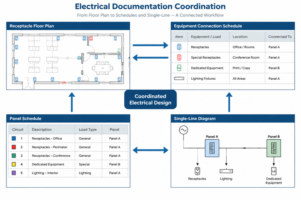
- Every circuit tag refers to an existing panel.
- Plan circuit identifiers agree with the corresponding schedule entries.
- Dedicated equipment appears consistently on the plan and schedule.
- Spare or unassigned schedule positions are not accidentally shown serving plan devices.
- Multi-sheet continuation methods are understandable.
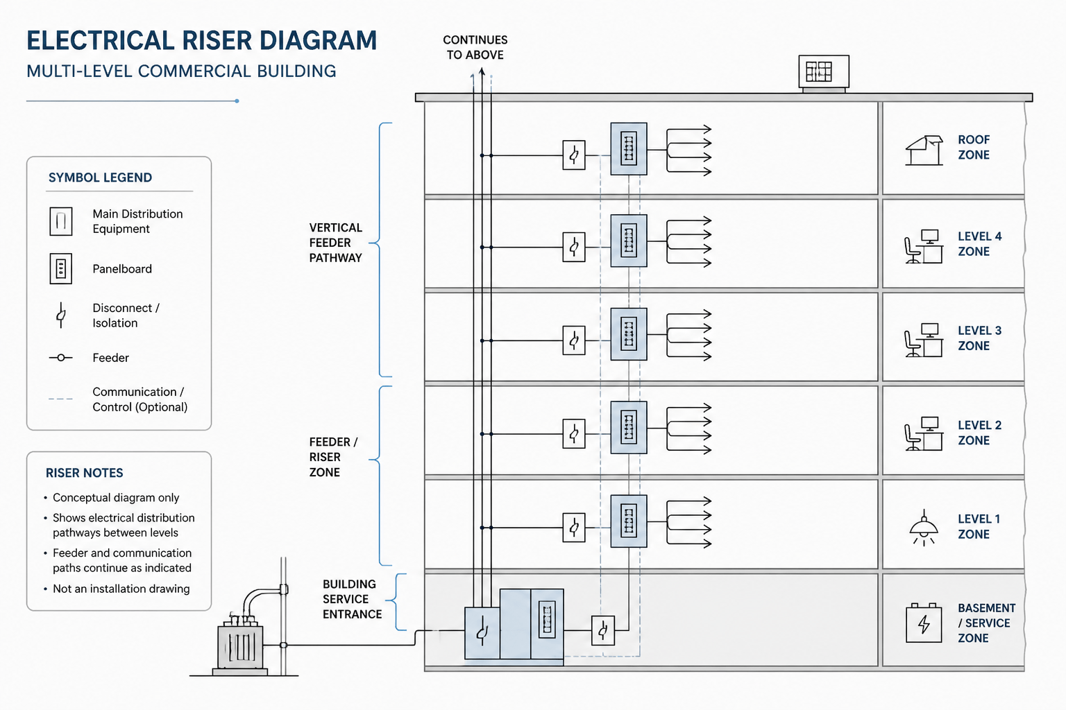
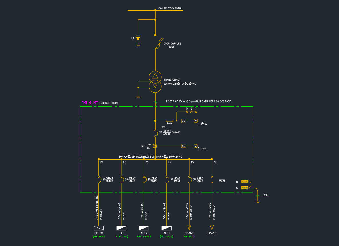
- Panel names are consistent across plans, schedules, and single-line diagrams.
Automated extraction can assist with this process, but it does not replace visual review. Text, blocks, and schedules may be technically matched while still communicating an incorrect equipment relationship.
Organize CAD layers by function
Separate device symbols, circuit graphics, tags, notes, and equipment references where the project CAD standard supports that structure. Functional separation improves plotting control and makes it easier to isolate information during review.
Avoid creating a unique layer for every minor device variation unless it provides a real coordination or display benefit. Excessive layer subdivision can make editing harder without improving the issued drawing. Layer names should be understandable to other team members and consistent across sheets.
Manage crowded plan areas
Kitchens, laboratories, workshops, equipment rooms, and dense office layouts can become difficult to read at the main plan scale. Do not solve congestion by shrinking text or stacking symbols until they are indistinguishable.
Better options include enlarged plans, interior elevations, equipment connection schedules, and keyed notes. A main plan can establish the overall location and direct the reader to a larger-scale view for detailed placement. Ensure that the enlarged view and overall plan are coordinated so devices are not duplicated or omitted.
Complete a focused quality-control review
Review the drawing both in CAD and in its intended issue format. A symbol arrangement that looks clear while zoomed in may fail when plotted or viewed on a full sheet.
- Confirm that all symbols appear in the legend.
- Check for duplicate or overlapping blocks.
- Review device orientation along walls and casework.
- Find symbols left behind after rooms or equipment moved.
- Check tags for collisions with doors, dimensions, and other notes.
- Compare specialty outlets with equipment schedules and architectural elevations.
- Verify circuit and panel references across the drawing set.
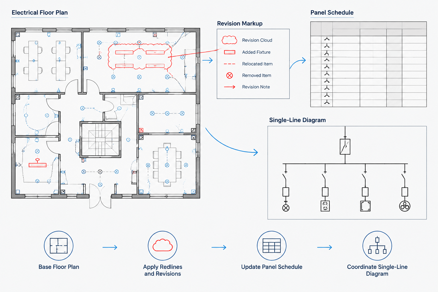
- Confirm that demolition, existing, and new-work graphics are distinguishable where applicable.
- Search for temporary notes, unresolved placeholders, and unverified values.
A clear receptacle and small-power plan is the result of coordinated information, not symbol density. Consistent blocks, readable annotations, disciplined circuit references, and careful cross-checking help transform a collection of outlet symbols into a reliable project document.
Leave a Reply
You must be logged in to post a comment.