
Floor box CAD drawings must communicate more than a device location. They connect a compact plan symbol with service requirements, orientation, furniture layouts, pathways, floor conditions, schedules, and referenced details. Poke-through devices require similar coordination, but their documentation should also account for the floor penetration and conditions below.
This reference explains how to organize those relationships without overloading the electrical plan or implying an unverified product configuration. It is intended for CAD drafters, electrical designers, engineers, students, and reviewers coordinating floor service devices across a drawing set.
Floor boxes and poke-through devices may occupy only a small area on an electrical plan, but each location can involve several coordinated decisions. Power, data, audiovisual cabling, furniture, floor finishes, structural conditions, and architectural layout may all affect the drawing. A symbol placed without supporting information can leave reviewers unsure what the device contains, how it is oriented, or which discipline is responsible for associated pathways.
Effective floor box CAD drawings treat the plan symbol as one part of a coordinated documentation system. The plan establishes location and orientation, a tag identifies the device configuration, schedules describe services, and referenced details clarify physical relationships that cannot be shown clearly at plan scale.
Floor Box and Poke-Through Documentation Are Not Interchangeable
Both device types provide services at or through a floor, but they should not automatically share one generic symbol. A floor box is typically coordinated as an assembly within a floor construction or slab condition. A poke-through device passes through an existing or planned floor opening and may serve spaces above, below, or both, depending on the selected assembly and project design.
The drawings should use the terminology established by the project team and verified product information. If the device type has not been selected, label it as a design-intent or generic assembly rather than drawing a manufacturer-specific configuration. This avoids implying that an unverified CAD block represents the final construction.
| Drawing concern | Floor box documentation | Poke-through documentation |
|---|---|---|
| Primary plan reference | Box center, cover orientation, and floor location | Penetration center, device orientation, and affected floor areas |
| Supporting views | Section, service layout, or mounting detail | Section through floor and pathway relationship |
| Coordination focus | Floor construction, furniture, finishes, and pathways | Floor opening, ceiling below, structure, and pathways |
| Configuration record | Device tag, service schedule, or keyed note | Device tag, service schedule, or keyed note |
Build the Plan Symbol Around Drawing Intent
A useful symbol must remain recognizable at the plotted scale without attempting to reproduce every part of the physical device. The block can show a simple outer boundary, insertion point, orientation indicator, and tag attribute. Internal graphics may distinguish power-only, communications-only, and combined-service arrangements, but excessive detail can become unreadable or merge with architectural linework.
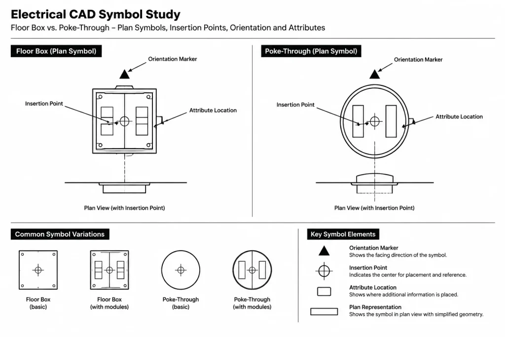
Use a consistent insertion point, normally tied to the location that the design team intends to dimension or coordinate. Do not alternate between the edge of the cover, the center of the opening, and the center of the box without clearly documenting the convention. If the cover or service compartments have a meaningful orientation, include a subtle directional feature in the block and define what it represents.
Useful block data
- A unique device or type tag.
- A service classification, such as power, data, audiovisual, or combined service.
- A circuit reference when circuiting is part of the plan scope.
- A detail or schedule reference where additional information is provided.
- An orientation attribute or visible marker when rotation affects coordination.
- A status field when existing, new, relocated, or future devices must be distinguished.
Keep attributes concise. Long descriptions generally belong in a schedule or note column rather than beside the symbol. If a block includes optional visibility states or alternate graphics, confirm that exported, printed, and exchanged drawings display the intended state correctly.
Locate Devices from Stable References
Floor device locations are often driven by furniture rather than walls. Furniture, however, may change throughout design. A robust drafting workflow records both the current design relationship and a stable method of locating the device.
Coordinate the symbol against architectural grids, structural grids, fixed walls, finish patterns, casework, and approved furniture reference points as appropriate. Avoid relying solely on a movable table outline or an unverified workstation block. Where dimensions are provided, the drawing should make clear whether they locate the center of the box, the center of the cover, or another defined point.
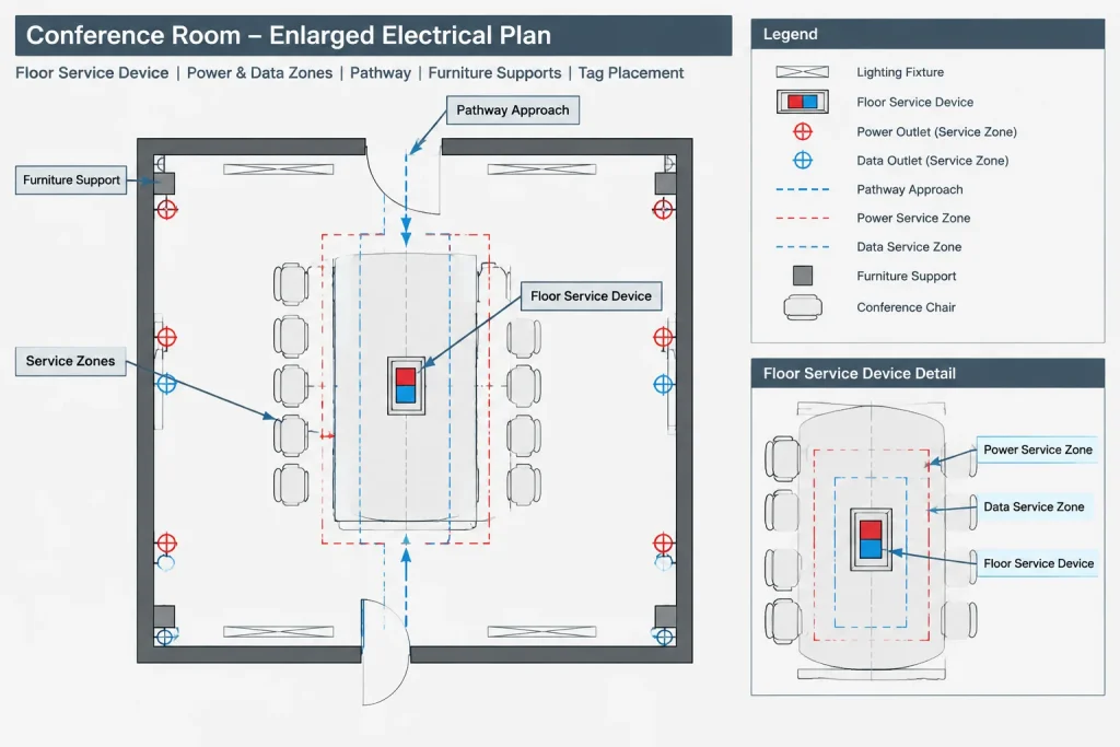
Orientation deserves a separate check. A centered symbol can still be wrong if service doors open toward an obstruction, compartments conflict with furniture supports, or the intended user side has changed. When a device serves a conference table or modular furniture assembly, compare the electrical plan with the latest furniture power and data entry points.
Separate Service Intent from Physical Compartment Design
A plan may need to communicate several service types at one location, but that does not mean the drafter should invent the internal construction of the assembly. Use the device tag and schedule to document required services while reserving exact compartment layouts, fittings, and internal arrangements for verified details or product information.
A simple schedule can connect plan intent to later selection and coordination:
| Schedule field | Purpose |
|---|---|
| Type tag | Links the plan symbol to a defined configuration |
| Service description | Identifies the intended mix of power and low-voltage services |
| Cover or finish note | Records architectural coordination requirements without assuming an unverified product |
| Pathway reference | Points to conduit, cable tray, underfloor system, or another documented route |
| Detail reference | Directs readers to a section, mounting detail, or service arrangement |
| Remarks | Captures special coordination conditions or responsibility notes |
Where power and communications are shown on separate plans, use the same device identifier on both sheets. Independent tags can make one physical assembly look like two unrelated devices. If discipline-specific symbols are necessary, provide a shared reference that allows the locations and configurations to be reconciled.
Use Enlarged Plans and Details for Crowded Conditions
A general floor plan is rarely the best place to show every component. Enlarged plans can clarify service orientation, nearby furniture, pathway approach, and relationships to adjacent devices. Sections can show the floor assembly, ceiling space below, pathway direction, and the boundary between electrical work and work assigned to other disciplines.
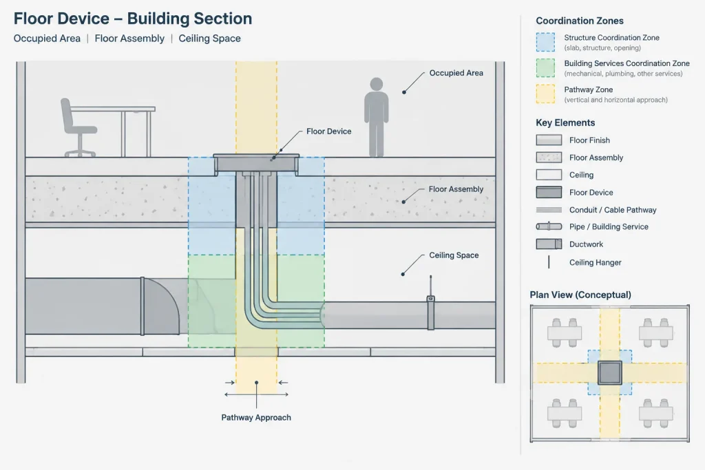
Detail graphics should remain diagrammatic unless verified dimensions and product data are available. Clearly differentiate between a typical concept and a project-specific assembly. If a generic library detail is used as a starting point, review its layers, notes, terminology, linework, and implied construction before adding it to the project set.
Information commonly coordinated in details
- The plan reference point and device orientation.
- The relationship to the finished floor and adjacent finish transitions.
- The pathway approach and separation of service groups where required by the design.
- The floor or slab condition represented by the detail.
- Associated openings and the discipline responsible for documenting them.
- References to verified architectural, structural, communications, or audiovisual information.
Coordinate the Area Above and Below the Floor
Floor devices are three-dimensional coordination items. A location that appears clear on the plan above may conflict with structural framing, ceiling systems, lighting, ducts, piping, or equipment below. Overlay review should therefore include relevant backgrounds from both sides of the floor.
For poke-through devices, check that the same center point is represented consistently on the plan above, the reflected ceiling or coordination plan below, and any associated section. For floor boxes, verify the relationship to the documented floor construction and pathway route. The electrical drawing should identify coordination needs without presenting unverified structural openings or construction details as final.
Apply a Repeatable CAD Workflow
- Confirm the current backgrounds. Load the latest architectural, structural, furniture, and relevant technology references using the project coordinate system.
- Classify each device. Determine whether it is a floor box, poke-through, furniture interface, or another floor service condition.
- Place a controlled block. Use the defined insertion point, assign the correct layer, rotate the symbol, and populate its identifying attributes.
- Assign a configuration tag. Link the device to a schedule or keyed description rather than placing long text around the symbol.
- Add circuit and pathway references. Show only the level of routing intent appropriate to the drawing type.
- Create supporting views where needed. Use enlarged plans or sections for locations that cannot be understood from the general plan.
- Cross-check other disciplines. Compare furniture, floor finishes, structural conditions, ceiling elements below, and technology service requirements.
- Review the plotted output. Confirm that symbols, orientation markers, tags, leaders, and background screening remain readable at issue scale.
Quality-Control Checks Before Issue
- Every plan symbol has a valid tag or clear description.
- Every tag appears in the applicable legend or schedule.
- The insertion point convention is consistent across the project.
- Power and low-voltage plans refer to the same physical assembly consistently.
- Device orientation agrees with furniture and intended access.
- Locations have been checked against structural and ceiling conditions.
- Detail references point to existing, current views.
- Generic details do not contain leftover project names, product assumptions, or irrelevant notes.
- Existing, new, relocated, and future devices are graphically distinguishable where required.
- No CAD block is treated as proof that a selected assembly is suitable for the actual floor construction.
A Small Symbol with a Large Coordination Role
Clear floor box CAD drawings do more than place device symbols near tables and workstations. They establish a traceable relationship among location, orientation, service intent, pathways, schedules, details, and surrounding construction. By keeping plan graphics simple and moving configuration data into coordinated schedules and views, the drawing set becomes easier to review and revise. Final assemblies, openings, dimensions, and installation conditions should always be verified against project requirements and current information from the responsible design disciplines and selected manufacturers.
Use a Clear Information Hierarchy
The most reliable documentation assigns each type of information to the view where it can be understood and maintained most easily. The general plan should establish the device location, orientation, identifier, and essential connections. A schedule can define the service intent and configuration represented by that identifier. Enlarged plans and sections can then explain physical relationships that would be unclear at the general plan scale.
This hierarchy also supports revisions. If the required service mix changes while the device location remains fixed, the schedule may be updated without rebuilding crowded plan annotations. If furniture moves, the plan location and orientation can be reviewed while the shared device identifier preserves the relationship to other sheets.
Track Coordination Decisions Through Revisions
Floor service locations often develop alongside architectural, structural, furniture, communications, and audiovisual information. During each drawing update, distinguish between confirmed information, current design intent, and unresolved coordination. A generic block should remain generic until verified selection information is available.
- Location source: Record which background or approved reference established the placement.
- Orientation source: Confirm whether rotation follows furniture access, pathway approach, cover operation, or another documented condition.
- Service source: Reconcile the electrical plan with communications and audiovisual requirements where those services share an assembly.
- Detail status: Check that referenced views represent the current floor, furniture, and pathway conditions.
- Responsibility boundary: Use notes and references to identify coordination needs without assigning unverified work to another discipline.
Review the Device as One Record Across Multiple Views
A useful final review follows each device identifier through the complete drawing set. Locate the symbol on the plan, find the matching schedule entry, verify any detail reference, compare related discipline drawings, and confirm that the same orientation and status are communicated throughout. This record-based review is more dependable than checking isolated symbols because it reveals mismatched tags, duplicate locations, outdated details, and conflicting service descriptions.
The CAD block itself is only a graphic and data container. Product selection, floor compatibility, opening requirements, pathway construction, and installation conditions must be verified through the responsible project disciplines and current manufacturer information.
Frequently Asked Questions
Should floor boxes and poke-through devices use the same CAD symbol?
Not automatically. The graphics should distinguish the device types when that difference affects coordination, detailing, or review. If a project uses a shared base symbol, the tag, legend, schedule, and supporting details should still identify the intended condition clearly.
What should the insertion point of a floor device block represent?
It should represent the project’s documented location reference, such as the coordinated device or opening center. The important requirement is consistency. Drafters and reviewers should not have to guess whether dimensions refer to a cover edge, box center, penetration center, or another point.
How should combined power and low-voltage services be shown?
Use a shared device identifier and a coordinated schedule or description to record the required services. Avoid inventing internal compartments or fittings when the physical assembly has not been verified. Related discipline plans should make it clear that their symbols refer to the same physical location.
When is an enlarged plan appropriate?
An enlarged plan is useful when the general plan cannot clearly show orientation, furniture relationships, pathway approaches, adjacent devices, or service access. A section may also be needed when conditions above and below the floor are important to understanding the design intent.
Can a manufacturer CAD block be treated as final product coordination?
No. A block may assist with representation, but it does not by itself confirm that the assembly matches the floor construction, required services, finishes, pathways, or project requirements. Its geometry, attributes, notes, layers, and product status must be reviewed before use.
How can drawing teams prevent duplicate floor device records?
Use one controlled identifier for each physical assembly and reconcile that identifier across electrical, communications, audiovisual, furniture, schedule, and detail references. Duplicate or discipline-specific graphics should point back to the same coordinated record.



Leave a Reply
You must be logged in to post a comment.