
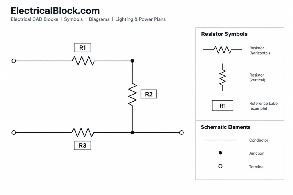
This schematic resistor symbols DWG resource is intended for circuit-diagram drafting rather than physical equipment layout. It gives CAD users reusable graphical content that can be placed into electrical schematics, educational drawings, and related technical documentation.
Before incorporating any symbol into a drawing set, compare its appearance with the project legend and the drafting convention used by the design team. Resistor graphics can vary by documentation style, so consistency across the complete schematic is more important than mixing multiple visual conventions.
Discover a comprehensive DWG file featuring detailed Schematic Resistor Symbols, perfect for electrical engineers and designers. This CAD Block provides a high-quality collection of resistor symbols for quick integration into your electrical schematics and circuit diagrams. Designed for precision, these symbols streamline the drafting process, ensuring accuracy and clarity in your project documentation. Fully compatible with AutoCAD and other leading CAD software, this resource is ideal for electrical circuit design, educational purposes, and professional engineering applications. Enhance your workflow with these easy-to-use, standardized schematic resistor symbols today.
Please log in or register to download this file.
How resistor symbols function in a schematic
A schematic resistor symbol communicates the presence and electrical relationship of a resistive component. It does not show the component’s physical size, installation position, enclosure, or mounting arrangement. Those details belong in equipment layouts, assembly drawings, schedules, or other supporting documents.
The symbol should be accompanied by the identifiers and design information required by the project. Depending on the documentation workflow, this may include a component reference, descriptive note, value field, or connection information. Any added text should remain legible and should not obscure conductors or nearby symbols.

Recommended CAD review before use
- Inspect the geometry: Check that lines, connection points, and text display correctly after opening or importing the DWG file.
- Review layers: Move or map the content to the project’s established layers when necessary. Separating symbols, conductors, annotations, and reference information can simplify later revisions.
- Confirm drawing scale: Schematic symbols are diagrammatic, but their plotted size still needs to remain consistent with other symbols and labels on the sheet.
- Check insertion behavior: Verify the block base point and rotation so the symbol aligns cleanly with circuit lines.
- Apply the project legend: Make sure the chosen graphic matches the resistor representation identified in the drawing legend or documentation standard.
- Clean imported content: Review duplicate definitions, unwanted layers, line types, and text styles before adding the block to a controlled CAD library.
Keeping circuit drawings readable
Place resistor symbols so that conductors meet their intended terminals without small gaps or unnecessary overlaps. Maintain clear spacing around reference designations and avoid placing unrelated notes directly across circuit paths. Repeated components should follow the same orientation and annotation pattern unless circuit logic requires a different arrangement.
For larger drawing sets, use a consistent naming method for block definitions and component references. This supports editing, symbol searches, drawing checks, and coordination with bills of materials or component schedules. If the source block has no attributes, project-specific labels can be added through the office’s established annotation workflow.
Related drawing-reference topics
This block collection can be considered alongside electrical CAD symbols, schematic legends, circuit-diagram conventions, block-library management, and CAD layer organization. Those related topics help explain not only how a resistor is drawn, but also how symbols are controlled and documented throughout a coordinated electrical drawing set.
Important verification note
A CAD symbol is a drafting resource, not proof that a circuit design has been reviewed or approved. Confirm symbol meaning, component identification, connectivity, and documentation requirements with the applicable project criteria before issuing drawings.
Frequently asked questions
What is included in this resistor symbol resource?
The source describes a DWG collection of schematic resistor symbols for use in electrical schematics and circuit diagrams. Open the file and review the included block definitions before transferring them into a project library.
Are schematic symbols drawn to physical equipment size?
No. Schematic symbols communicate circuit function and connectivity rather than the physical dimensions or installed appearance of a component.
Can the DWG file be used outside AutoCAD?
The source identifies compatibility with AutoCAD and other leading CAD software. Because DWG handling can differ between applications, check block geometry, layers, text, line types, and insertion points after import.

Should every resistor symbol look the same?
Drawing conventions may use different graphical representations. A project should apply one documented convention consistently and identify it through the legend or other drawing notes.
How should resistor blocks be organized in a CAD library?
Use clear block names, controlled layers, predictable insertion points, and consistent annotation practices. Avoid retaining unrelated source layers or duplicate block definitions that could complicate the drawing database.
What should be checked before plotting?
Review symbol visibility, conductor connections, text legibility, orientation, lineweight behavior, and consistency with the rest of the circuit diagram.












Leave a Reply
You must be logged in to post a comment.