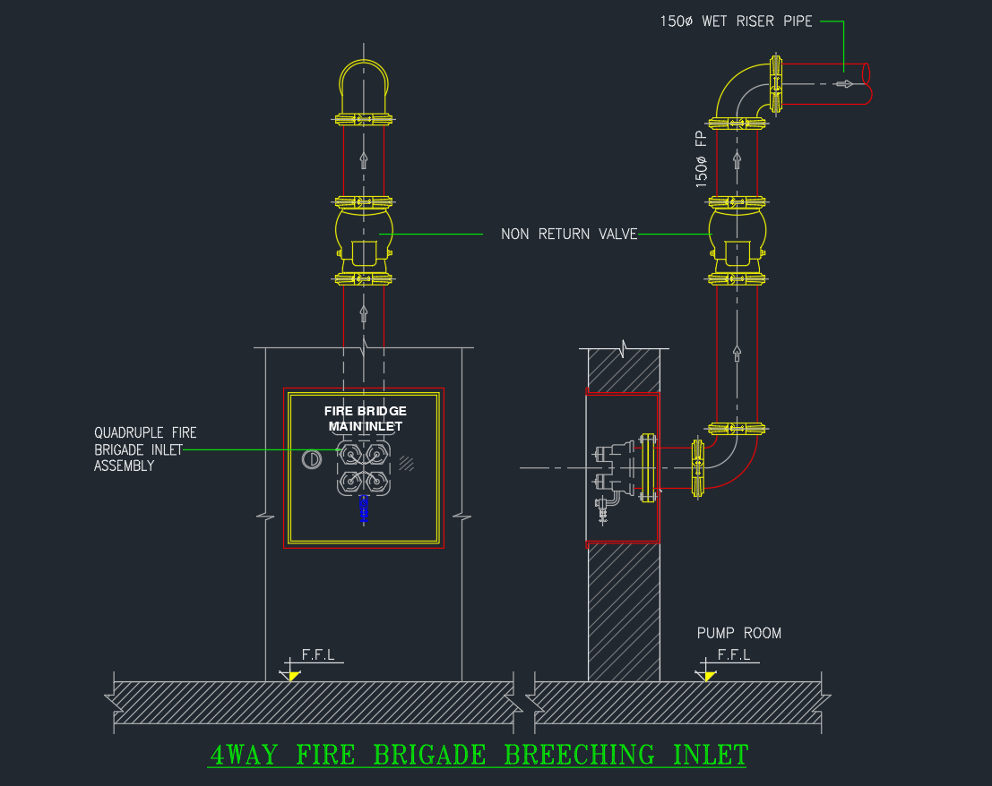
A Fire Brigade DWG provides editable CAD geometry for documenting emergency-response equipment or related fire-safety information. It can support architectural plans, site drawings, equipment layouts, and coordinated safety documentation where clear identification and consistent drafting are important.
Before adding the block to a project, review the included geometry, labels, layer organization, and drawing units. The meaning of each element should remain clear when it is placed alongside architectural backgrounds, access routes, utilities, and other electrical or life-safety symbols.
Download a high-quality Fire Brigade DWG file, perfect for architects, engineers, and designers working on safety and emergency response projects. This detailed CAD Block includes essential Fire Brigade elements for integration into building layouts and site plans. Compatible with AutoCAD and other leading CAD software, it ensures easy editing and seamless incorporation into your designs. Use this Fire Brigade DWG file to enhance your fire safety plans, optimize emergency routes, and comply with safety regulations in residential, commercial, or industrial projects. Ideal for professionals seeking precise, ready-to-use CAD resources.
Please log in or register to download this file.
Using the Fire Brigade DWG in a Drawing Set
The downloaded CAD content can be inserted into a working file or copied into a project-specific symbol library. Because office standards and consultant backgrounds vary, the block should be checked before it becomes part of a construction or permit drawing.
Recommended CAD Review
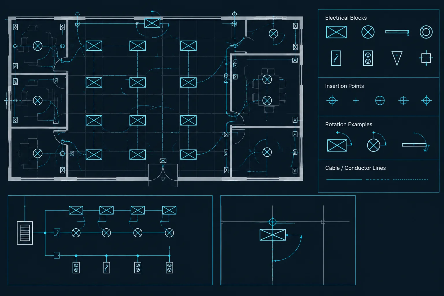
- Inspect the geometry: Confirm exactly which equipment, symbols, labels, or diagram elements are included rather than relying only on the file name.
- Verify drawing units: Compare the source file with the units used by the destination drawing before scaling or placing the content.
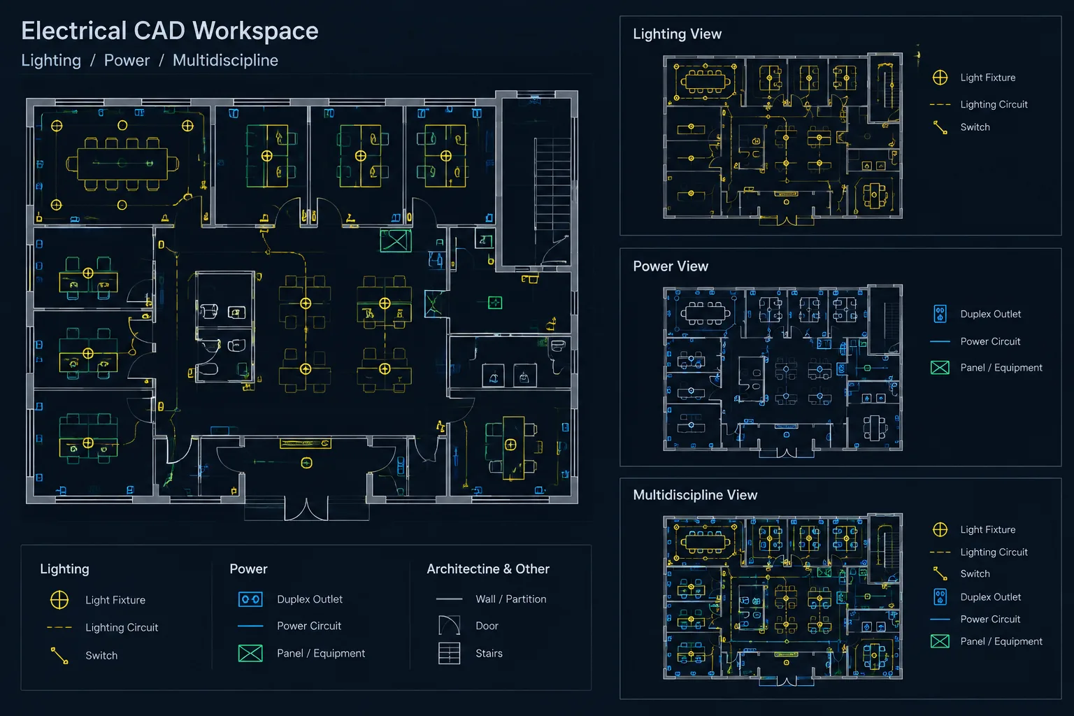
- Review layers: Move objects to approved project layers when necessary so lineweights, colors, visibility, and plotting behavior remain consistent.
- Check text and attributes: Replace generic wording with project-approved terminology and verify that editable attributes display correctly.
- Remove unnecessary content: Purge duplicate definitions or unused items according to the project team’s CAD workflow.
Placement and Coordination Considerations
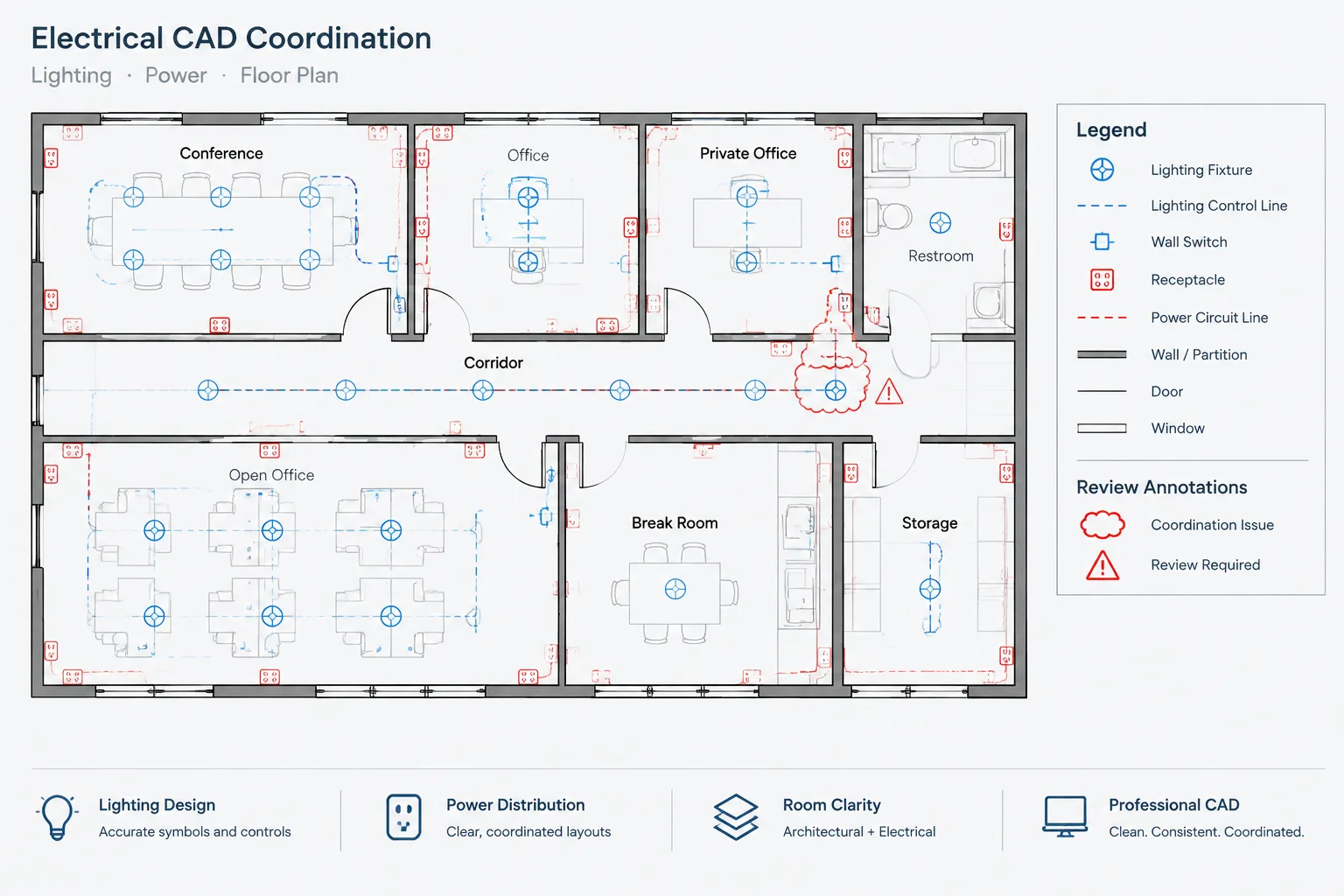
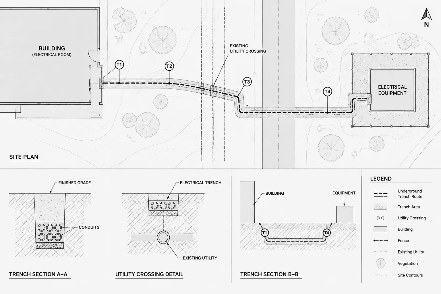
Fire brigade equipment graphics should be positioned in relation to the architectural plan and the intended drawing purpose. On a site plan, the surrounding context may include access areas, building outlines, gates, utilities, and emergency-response notes. On a floor plan, coordination may involve walls, doors, circulation paths, equipment rooms, and other life-safety information.
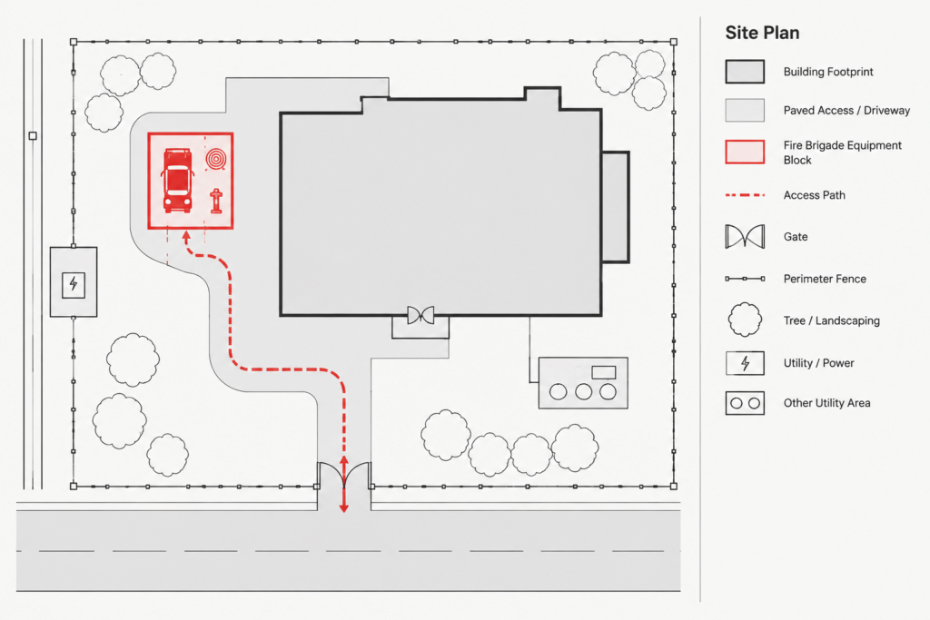
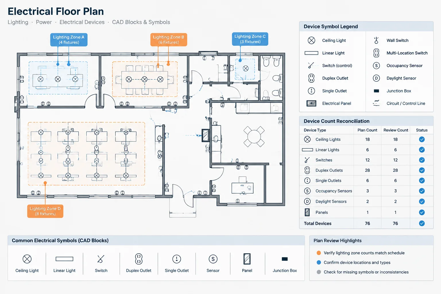
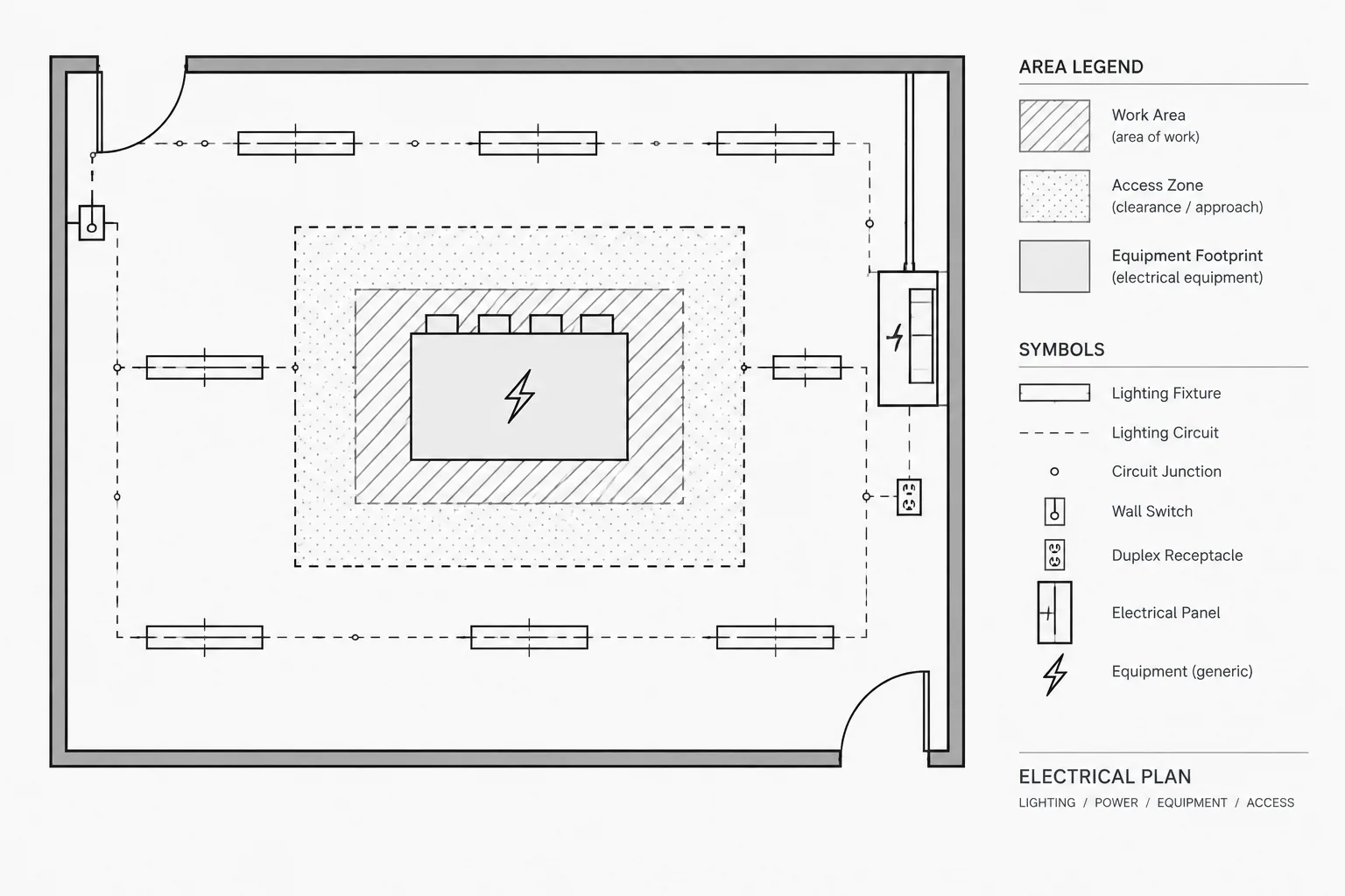
A symbol should not obscure dimensions, room names, circuit information, or critical route graphics. If the same block is used at different drawing scales, review line density and text readability in the plotted output rather than judging only from the model-space display.
Legends, Notes, and Symbol Consistency
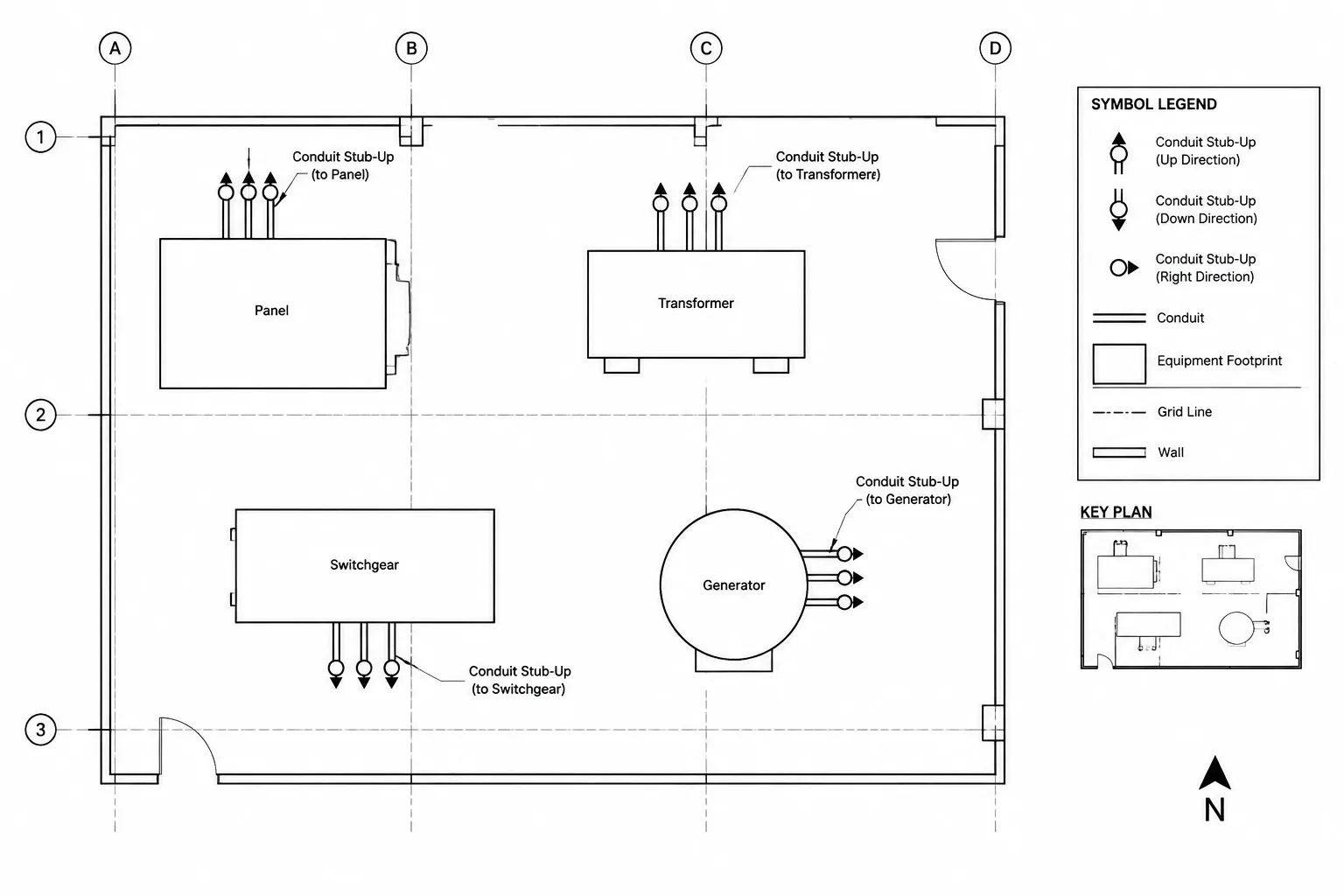
Include the graphic in the drawing legend when its meaning may not be immediately clear. The legend name, plan label, equipment schedule entry, and related note should use consistent terminology. Avoid assigning a new meaning to a familiar symbol without documenting that change.
Related drafting references may include fire safety symbols, emergency plan graphics, site-plan blocks, equipment-layout details, CAD layer conventions, and drawing-legend examples. Coordinating these resources helps readers distinguish emergency-response information from electrical power, lighting, communications, and general architectural content.

Professional Verification
A CAD block is a drafting resource, not evidence that a design meets regulatory or operational requirements. Equipment selection, location, access, identification, and required documentation must be reviewed against the project criteria and the requirements of the applicable authority. Project-specific approval remains necessary even when the geometry is clear and professionally drawn.
Fire Brigade DWG Frequently Asked Questions
What should I check before inserting the DWG?
Inspect the drawing units, layers, object types, text styles, attributes, and overall geometry. Confirm that the content represents what the project legend and notes say it represents.
Can the block be used in a site plan?
It can be incorporated into a site-plan workflow when its content is relevant to that drawing. Placement should be coordinated with the building outline, access information, utilities, annotations, and other emergency-response graphics.
Should the original CAD layers be retained?
That depends on the project CAD standard. Retain useful source organization when appropriate, or remap the objects to approved layers so plotting and visibility remain consistent across the drawing set.

Does inserting the block establish code compliance?
No. The block supplies editable drawing geometry only. Compliance depends on the complete design, project conditions, applicable requirements, and review by qualified professionals and relevant authorities.
How can the symbol remain readable on a busy plan?
Use clear layer control, appropriate lineweight hierarchy, uncluttered placement, and coordinated annotations. Review a plotted or published sheet to confirm that the block remains distinguishable from nearby electrical and architectural information.
Should the DWG be added to a company symbol library?
It may be added after review and standardization. Use a clear library name, document its intended meaning, remove unrelated objects, and align its layers and text with the organization’s drafting conventions.
Leave a Reply
You must be logged in to post a comment.