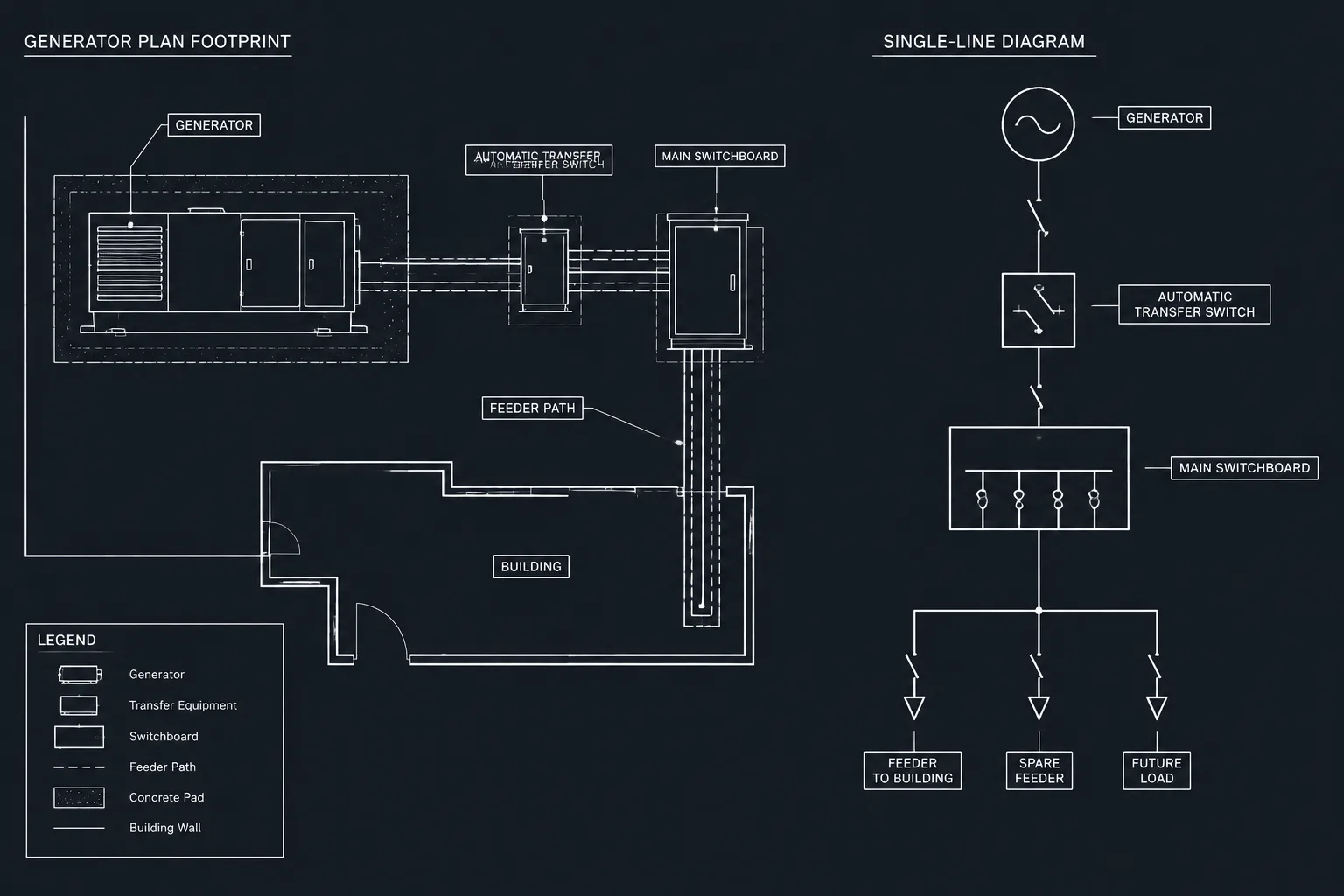
Generator drawings in CAD function as a coordinated documentation system rather than a single equipment block. Plans communicate physical placement, one-lines describe power relationships, schedules organize equipment data, and interface drawings connect the electrical scope with other disciplines.
The most reliable workflow gives each drawing a clear purpose while maintaining common equipment tags, connection references, status notes, and verification records. The following guidance explains how to organize those relationships without assuming that generic symbols or preliminary footprints represent approved project information.
A generator may appear as a single symbol on an electrical plan, but complete generator documentation usually extends across several drawing types. The floor or site plan establishes location, the single-line diagram explains the power path, schedules identify equipment relationships, and details clarify interfaces that cannot be communicated at plan scale.
The drafting challenge is not simply drawing the generator footprint. It is keeping equipment identifiers, feeder references, transfer equipment, control connections, and physical coordination consistent throughout the set. This guide outlines a practical CAD workflow for assembling and reviewing generator drawings without treating any generic block or detail as project-ready.
Begin with a drawing relationship map
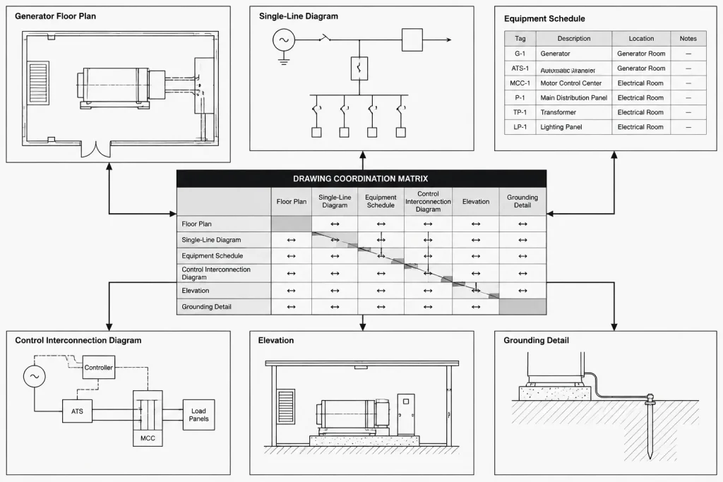
Before placing blocks, list every document that may contain generator information. The exact set depends on project scope, but the electrical documentation commonly includes:
- A site plan or floor plan showing the generator location and nearby electrical equipment.
- A power plan showing feeders, raceway routes, connection points, or continuation references.
- A single-line diagram showing how the generator relates to transfer equipment, distribution equipment, and connected systems.
- An equipment schedule or connection schedule containing coordinated equipment identifiers and drawing references.
- Control or interconnection diagrams when operational relationships cannot be conveyed clearly on the single-line diagram.
- Equipment elevations, sections, or enlarged plans where access, routing, or adjacent construction requires closer coordination.
- Grounding and bonding diagrams or details when those requirements are documented separately.
A simple relationship map helps the drafter identify where information originates. For example, the single-line diagram may be the primary source for the power topology, while the plan is the primary source for physical location. Neither view should be edited independently without checking the other.
Separate the diagram symbol from the physical footprint
The generator representation used on a single-line diagram should not be treated as a scaled equipment outline. Diagram symbols communicate electrical function and connectivity. Plan and elevation blocks communicate occupied space, orientation, service sides, connection regions, and relationships to surrounding construction.
A useful CAD library may therefore contain several related representations:
- A simplified generator symbol for single-line diagrams.
- A generic plan footprint used during early coordination.
- A project-specific plan outline based on verified equipment information.
- Front or side elevation graphics for coordination views.
- Separate access-zone, housekeeping-base, or connection-zone graphics.
Keep these representations associated through a common equipment identifier, not by making them identical graphics. If manufacturer or supplier information is unavailable, clearly distinguish a preliminary coordination footprint from verified project geometry.
Draft the physical plan around interfaces
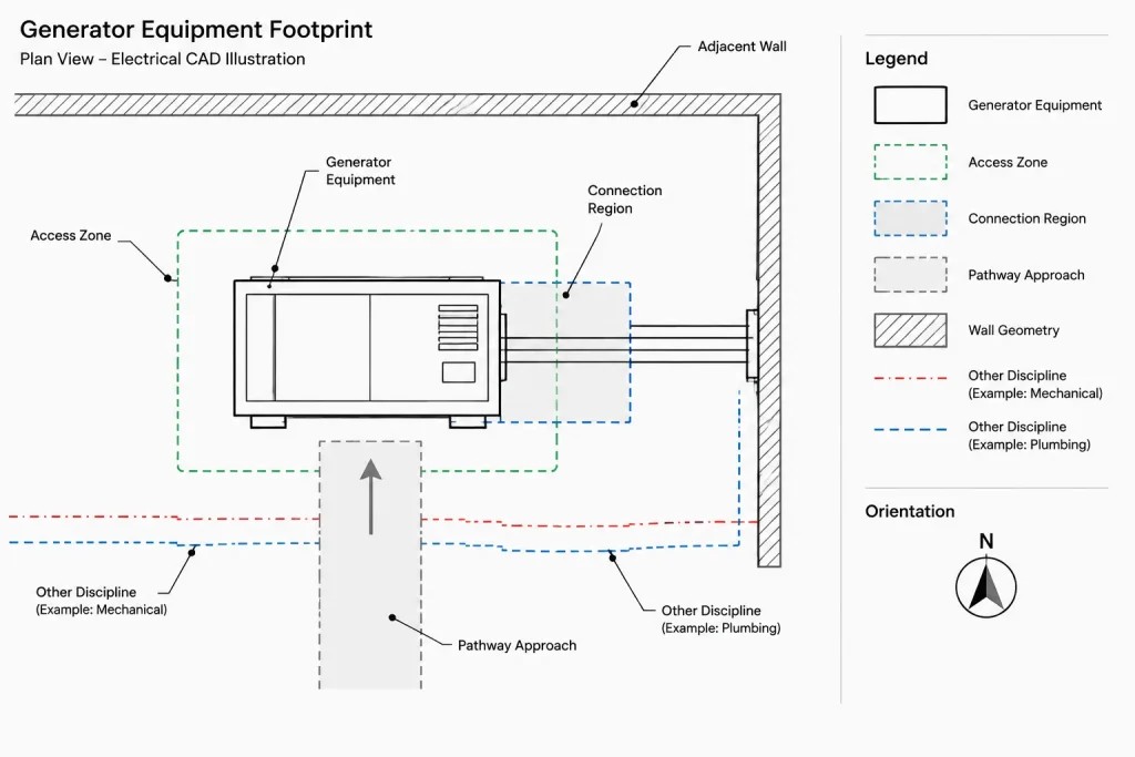
On a floor or site plan, the generator block is only the center of a larger coordination area. The drawing should make it possible to understand where electrical pathways approach the equipment and what nearby systems may affect the layout.
Show orientation clearly
Use an orientation that can be checked against elevations, connection information, and adjacent equipment. A generic rectangle without a defined front, service side, or connection side can be misleading, even when its overall outline is correct.
Orientation indicators should remain on a dedicated annotation or equipment-information layer when they are not intended to plot on every plan type. Do not mirror an asymmetric generator block merely to fit a layout; mirroring may reverse connection locations and service relationships.
Coordinate pathways and connection regions
Show feeder routes at the level of detail appropriate to the drawing. A diagrammatic route may be sufficient during early design, while a coordination plan may need entry direction, transition points, underground or overhead status, and references to sections or details.
Avoid terminating a raceway line at an arbitrary point on the equipment outline. Use a documented connection region or a clearly labeled approximate connection point until verified information is available. This makes the uncertainty visible and creates an item that can be tracked during coordination.
Control access graphics separately
Access and working zones can make a plan difficult to read if they use the same lineweight as equipment or walls. Place them on controlled layers with distinct linetypes, screening, or hatching. These graphics should indicate a coordination concern rather than imply that a generic block proves compliance. Required spaces must be checked against the actual equipment, project criteria, and applicable requirements.
Build a readable generator single-line diagram
The single-line diagram should explain the power relationship without attempting to reproduce the physical plan. Arrange the diagram so the normal source, generator source, transfer equipment, distribution equipment, and major loads can be followed in a consistent direction.

Important drafting elements include:
- Unique tags for the generator and each related transfer or distribution device.
- Clear source and destination labels on feeders.
- Consistent continuation references where the power path leaves the sheet.
- Distinct linework for power connections and control or monitoring relationships.
- References to schedules or notes rather than repeated, potentially conflicting data.
- A visible distinction between installed equipment and future, optional, or existing equipment.
Do not infer operational behavior solely from symbol proximity. If transfer logic, bypass arrangements, multiple sources, or selective load operation must be communicated, use an appropriate diagram and explanatory notes. The single-line should remain readable rather than becoming a dense substitute for every control document.
Coordinate power, control, and monitoring information
Generator drawing sets often contain several types of connectivity. Keeping them visually and logically separate reduces ambiguity.
| Information type | Typical drawing location | Coordination focus |
|---|---|---|
| Primary power path | Single-line diagram and power plan | Sources, destinations, equipment tags, and feeder references |
| Starting and transfer relationships | Control or interconnection diagram | Terminal references, cable identifiers, and functional intent |
| Remote status or alarms | Interconnection diagram or system diagram | Interface points, receiving system, and responsibility boundaries |
| Physical connection locations | Plan, elevation, or detail | Entry direction, connection region, and adjacent construction |
| Grounding and bonding intent | Single-line, grounding diagram, or detail | Consistent symbols, notes, and cross-references |
If control cables appear on both a plan and an interconnection diagram, use matching cable or circuit identifiers. Plan routing may be diagrammatic, but the from-to relationship should agree with the diagram. Where another discipline or vendor supplies part of the system, identify the interface boundary rather than drawing an unsupported internal connection.
Use schedules as coordination tools
A generator equipment schedule can serve as an index to related documentation, even when detailed product data is maintained elsewhere. Useful fields may include the equipment tag, service description, location, supplied systems, associated transfer equipment, drawing references, and verification status.
Only include technical characteristics that have a reliable project source. Empty or unresolved values should be tracked as coordination items instead of being filled with assumptions copied from a generic block. Attributes can help populate schedules, but automated extraction still requires review for duplicate tags, outdated blocks, and nonprinting reference objects.
Document non-electrical interfaces without designing them by implication
Generator installations interact with architectural, structural, mechanical, civil, controls, and sometimes communications drawings. Electrical drawings should identify relevant interfaces while avoiding unsupported design detail from another discipline.
Common coordination subjects include equipment bases, enclosure limits, ventilation relationships, exhaust routing, fuel-system interfaces, drainage considerations, sound-control features, weather exposure, vehicle access, lifting or replacement paths, and remote monitoring connections. These items can be shown with references, reserved zones, or coordination notes where appropriate.
Use discipline-neutral wording when responsibility has not been formally assigned. A note such as “coordinate opening with mechanical drawings” is more reliable than depicting a final opening size without verified information.
Apply a consistent CAD layer strategy
Separate permanent geometry from coordination aids so each view can be plotted for its intended purpose. A generator drawing may use distinct layers for equipment outlines, equipment tags, feeders, control pathways, underground routing, access zones, bases, connection points, demolition work, and nonplotting reference information.
Layer separation also helps when the same model supports an overall plan, an enlarged plan, and a coordination export. Avoid placing the complete generator block on one layer if portions of the block need different visibility or lineweight behavior.
Run a cross-drawing review before issue
A focused review should trace the generator through the drawing set rather than checking each sheet in isolation:
- Confirm that the equipment tag is identical on plans, diagrams, schedules, and details.
- Verify that the plan orientation agrees with elevations and known connection regions.
- Trace each shown power path from source to destination.
- Compare transfer equipment tags and served distribution equipment across all views.
- Check control and monitoring endpoints against interconnection diagrams.
- Confirm that existing, new, future, and optional statuses are represented consistently.
- Review external references and layer states to ensure coordination graphics are not accidentally omitted.
- Search for preliminary notes or placeholder blocks that require verification.
- Check that detail and sheet references point to current locations.
A well-coordinated generator drawing package does more than display equipment. It connects physical location, electrical function, operational relationships, and discipline interfaces through a consistent documentation system. Generic CAD blocks can accelerate that process, but their geometry, attributes, and technical meaning must always be checked against verified project information before issue.
Assign information ownership before revising the drawings
Conflicts often occur when the same information is edited independently in several views. Establish which document controls each category of information. The plan may control location and orientation, the one-line may control power topology, and a verified equipment document may control the physical outline and connection regions. Other drawings should reference that information rather than becoming competing sources.
Create an interface register
An interface register can be maintained as a project note, worksheet, or CAD data report. It should identify the item being coordinated, its originating document, the drawings affected by it, the responsible party, and its verification status. Typical entries include feeder termination regions, transfer-equipment relationships, remote monitoring points, equipment bases, pathway transitions, and discipline-provided openings.
Use clear status descriptions such as preliminary, awaiting verification, verified from project information, or supplied by others. These descriptions make uncertainty visible without filling unresolved fields with assumed data.
Revise from the controlling source
When a generator-related item changes, begin with the document that owns the information and then review every dependent view. A location change may affect feeder routing, detail references, elevations, and coordination backgrounds even when the one-line topology remains unchanged. A distribution change may affect the one-line, schedules, feeder labels, and plan annotations even when the equipment footprint stays in place.
Block attributes and extracted schedules can reduce repeated entry, but they do not replace this review. Hidden blocks, copied attributes, external references, and preliminary alternates may produce duplicate or obsolete records.
Include a plotted-output check
Review the issued appearance as well as the CAD model. Confirm that status graphics, control lines, access zones, connection markers, and continuation references remain distinguishable at the intended plot condition. Also verify that nonplotting coordination geometry is not carrying information needed to interpret the issued drawing.
This ownership-based approach creates a traceable path from verified information to each plan, diagram, schedule, and detail. It also makes later revisions easier to evaluate because the drafter can identify which documents depend on the changed item.
Frequently asked questions about generator CAD documentation
What should a generator CAD block contain?
A block should contain only information appropriate to its purpose. A one-line symbol needs clear connection and identification features, while a plan block may need an outline, orientation indicator, connection region, and separately controlled coordination graphics. Technical characteristics should come from verified project information rather than generic block attributes.
Should the same block be used on the plan and the one-line?
No. The one-line symbol represents electrical function and connectivity, while the plan block represents physical placement. The graphics can share an equipment tag and coordinated attributes without sharing the same geometry.
Can a generic generator footprint be used for layout coordination?
A generic footprint can support preliminary coordination if it is clearly identified as unverified. It should not be treated as proof of final dimensions, connection locations, access requirements, or project compliance.
Why is mirroring a generator plan block risky?
Mirroring may reverse service sides, connection regions, access relationships, and other asymmetric features. If orientation changes, compare the block with verified equipment information and related elevations rather than relying on a mirrored graphic.
How should control and monitoring connections be shown?
Keep power, control, and monitoring relationships visually distinct. Use matching identifiers across plans and interconnection diagrams, identify the sending and receiving systems, and show responsibility boundaries when another party supplies part of the connection.
What is the most important generator drawing review?
Trace the equipment through the complete drawing set. Confirm that tags, source and destination references, transfer-equipment relationships, statuses, orientation, connection regions, and detail references agree wherever they appear.












Leave a Reply
You must be logged in to post a comment.