
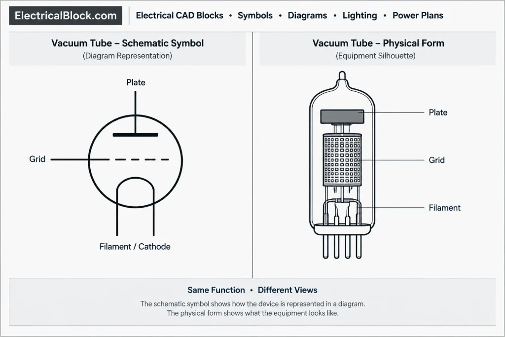
Electrical schematic tube symbols represent vacuum tubes and related electronic components in circuit documentation. Unlike physical equipment outlines, these symbols communicate circuit relationships, internal electrode arrangements, and connection points through simplified graphical conventions.
The DWG resource on this page is intended for schematic drafting rather than equipment placement or installation planning. Before incorporating any block into a drawing set, compare its graphic convention with the project legend, client requirements, and the notation already used throughout the schematic.
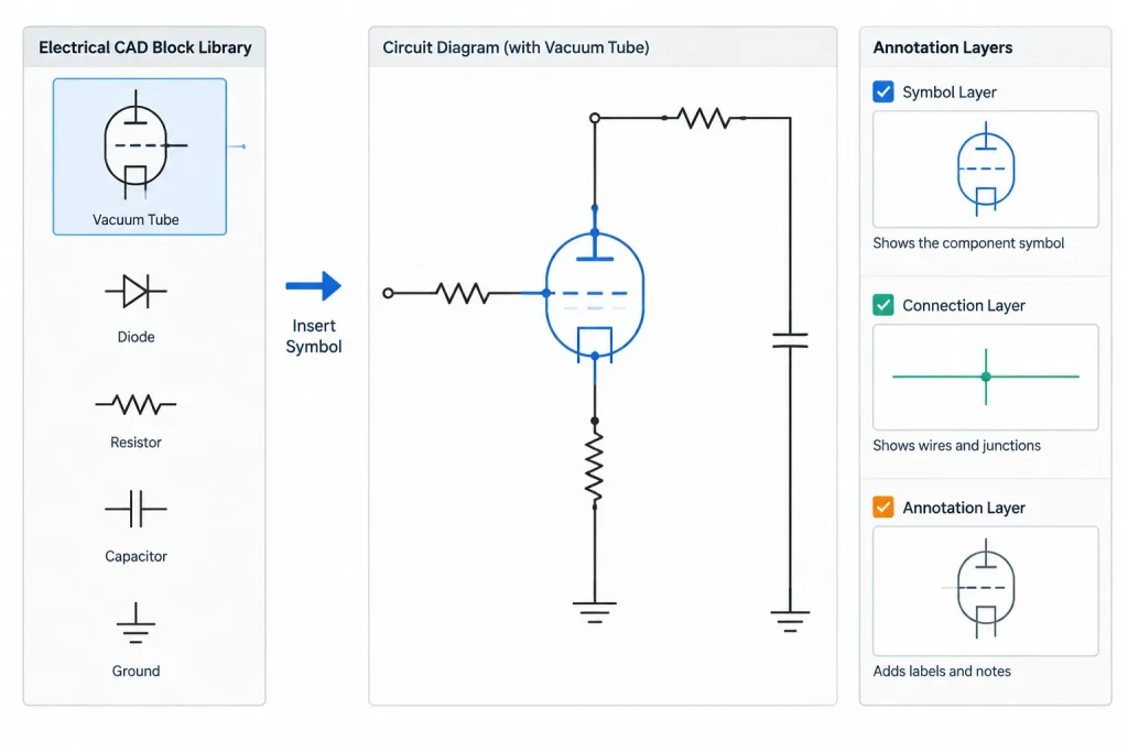
Download a professional set of Electrical Schematic Tubes Symbols in DWG format, compatible with AutoCAD and other CAD software. This library includes standardized tube and vacuum tube symbols used in electrical schematics, circuit diagrams, and electronic layouts. Each CAD block is clean, accurately scaled, and layered for seamless integration into technical drawings and engineering documentation. Ideal for electrical engineers, electronics designers, and BIM professionals, these schematic tube symbols save drafting time, maintain industry standards, and ensure clarity in electrical system designs. Perfect for educational, industrial, and electronic design projects.
Please log in or register to download this file.
Using Tube Symbols in an Electrical Schematic
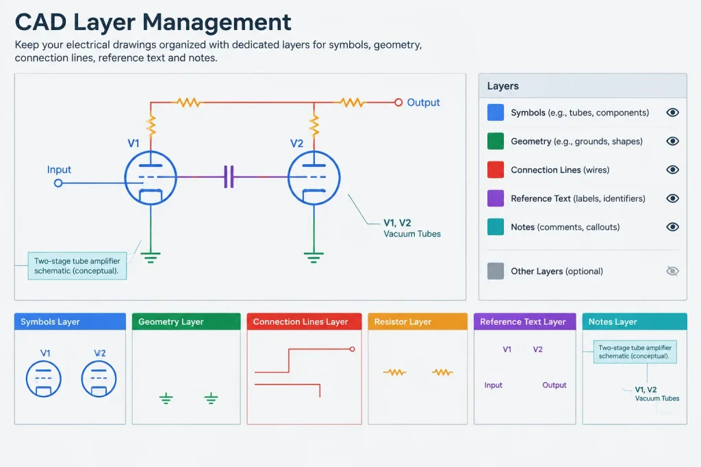
A tube symbol should be placed as part of the circuit diagram and connected through the project’s established wire or signal-line style. Its reference designation, pin information, component description, and related notes should remain separate from the symbol geometry whenever possible. This makes annotations easier to revise without editing the reusable block.
Because symbol appearance can vary among drafting systems and historical references, do not rely on shape alone to identify a component. The drawing legend, component schedule, and supporting documentation should establish the intended meaning.
DWG Review Checklist
- Insertion settings: Confirm the drawing units, block insertion behavior, and plotted appearance before adding the symbols to a working file.
- Layer organization: Move geometry, connection points, and annotations onto layers that match the project CAD standard.
- Line clarity: Check that electrode lines, envelopes, terminals, and circuit connections remain distinguishable at the planned plotting scale.
- Block definition: Use consistent names and avoid creating duplicate definitions when similar symbols already exist in the project library.
- Annotations: Keep reference designations and descriptive text readable, consistently aligned, and independent of unrelated geometry.
- Symbol verification: Compare the selected block with the project legend and the documented function of the component.
Schematic Symbols Versus Physical Layout Blocks
A schematic tube symbol is not a physical footprint, mounting template, or enclosure outline. It explains electrical or electronic relationships rather than the actual size and location of equipment. Physical layouts require separate manufacturer documentation and verified equipment geometry.
Related drawing references include electronic component symbols, schematic legends, connection diagrams, CAD layer conventions, and annotation workflows. Reviewing these topics together helps maintain consistent documentation across an electrical drawing set.
Frequently Asked Questions
What do electrical schematic tube symbols represent?
In this context, tube symbols refer to vacuum tubes and related electronic components shown in circuit and schematic documentation. They should not be confused with conduit, tubing, or raceway symbols used on building electrical plans.
Can these blocks be used as equipment layout drawings?
No. Schematic symbols communicate circuit function and connections. They do not establish physical dimensions, mounting locations, clearances, or fabrication requirements.
Should the downloaded symbol be used without modification?
Review it against the project legend, CAD standards, and component documentation first. Layer assignments, block names, attributes, annotation styles, and connection conventions may need to be coordinated with the destination drawing.
Why might tube symbols look different between drawings?
Symbol conventions can vary by drafting system, organization, application, and source material. Clear legends and component references help prevent ambiguity when symbols differ in appearance.
What should remain outside the reusable block?
Project-specific reference designations, circuit notes, and descriptive annotations are often easier to manage as separate text or attributes. This allows the core symbol geometry to remain reusable.



Leave a Reply
You must be logged in to post a comment.