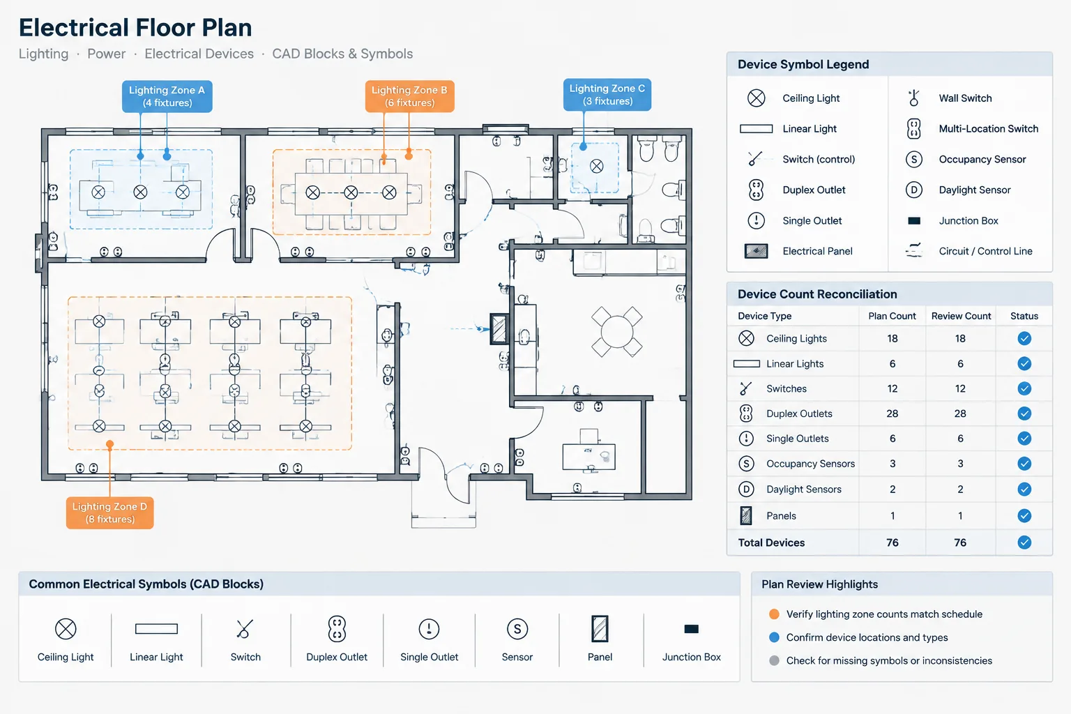
A CAD quantity becomes useful only when its scope, source, and classification are clear. Electrical device count verification tests whether symbols shown on plans correspond with the project legend, device tags, schedules, drawing status, and documented work boundaries.
The guidance below focuses on drawing review rather than automatic block totals alone. It explains how to distinguish physical devices from reference graphics, control duplicate representations, organize discrepancies, and preserve an audit trail that another reviewer can follow.
Electrical device counts are used for estimating, schedule preparation, design review, and drawing quality control. Yet a count taken directly from a CAD plan can be misleading. Duplicate symbols, hidden layers, overlapping viewports, demolition items, alternate work, and untagged devices can all produce incorrect totals.
Electrical device count verification is therefore more than selecting similar blocks and reading a quantity. It is a controlled reconciliation process that connects plan symbols with device tags, legends, schedules, drawing status, and project scope. The goal is not merely to produce a number, but to establish what that number represents and whether the drawings support it.
Define the purpose of the count first
Before reviewing the CAD files, determine why the count is needed. A quantity prepared for an internal design check may not use the same boundaries as a bid count or an equipment schedule.
Common count purposes include:
- Checking whether every scheduled device appears on a plan.
- Comparing quantities before and after a drawing revision.
- Preparing an equipment or fixture list from plan information.
- Confirming that repeated rooms use the intended device arrangement.
- Separating existing, demolished, relocated, and new work.
- Reviewing base scope, alternates, options, or future provisions.
- Finding symbols that are missing tags, circuit information, or schedule references.
Record the purpose in a count worksheet or review note. Without a defined purpose, two reviewers can count the same drawing correctly and still produce different totals because they included different scope.
Establish count boundaries
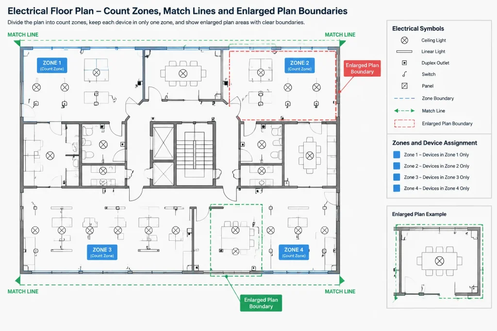
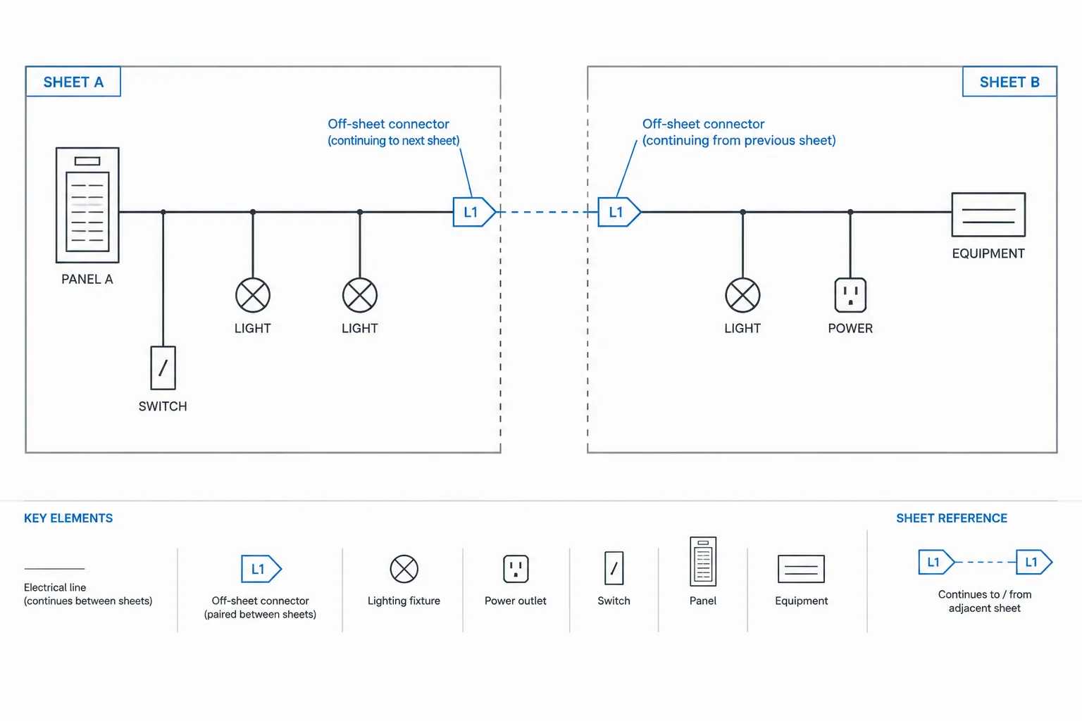
A reliable count requires clear spatial and documentary boundaries. Identify the floors, buildings, areas, and sheets included in the review. On large projects, divide the plan into count zones that correspond to rooms, wings, drawing zones, or match-line areas.
Pay special attention to enlarged plans. A device may appear on an overall floor plan for context and again on an enlarged plan for documentation. Unless the drawing explicitly represents separate devices, counting both views can double the quantity.
Typical boundary questions include:
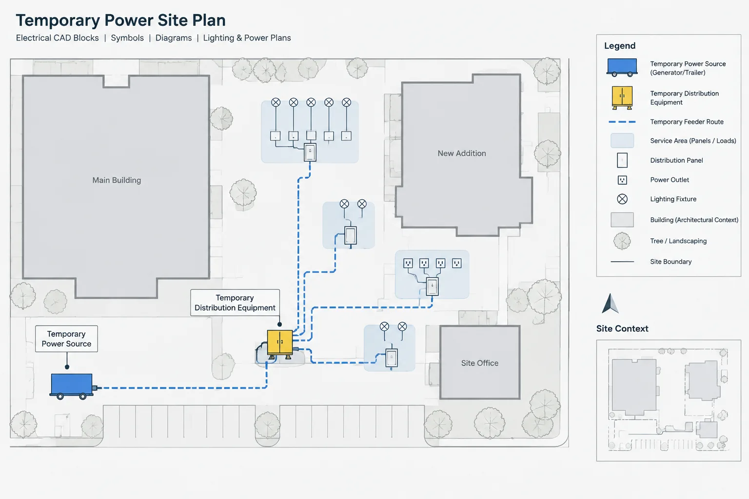
- Are roof, site, penthouse, and exterior devices included?
- Are typical units counted individually or represented by a typical layout?
- Do match lines overlap?
- Are devices shown in details or elevations also shown on floor plans?
- Are consultant drawings included in the same count?
- Are future devices included, excluded, or reported separately?
A simple boundary diagram can be useful when several sheets divide one floor. Shade or outline each count region and assign it a review identifier. This creates an audit trail and reduces gaps between reviewers.
Classify symbols before counting them
Not every visible electrical symbol should be treated as a unique countable item. Build a classification list before extracting or tallying quantities.
| Symbol category | Typical count treatment | Review concern |
|---|---|---|
| Individual device | Count each placed device | Check for duplicate or stacked blocks |
| Combination device | Count according to the documented assembly | Do not assume the graphic represents separate products |
| Typical or representative symbol | Use the stated repetition rule | Confirm where the typical condition applies |
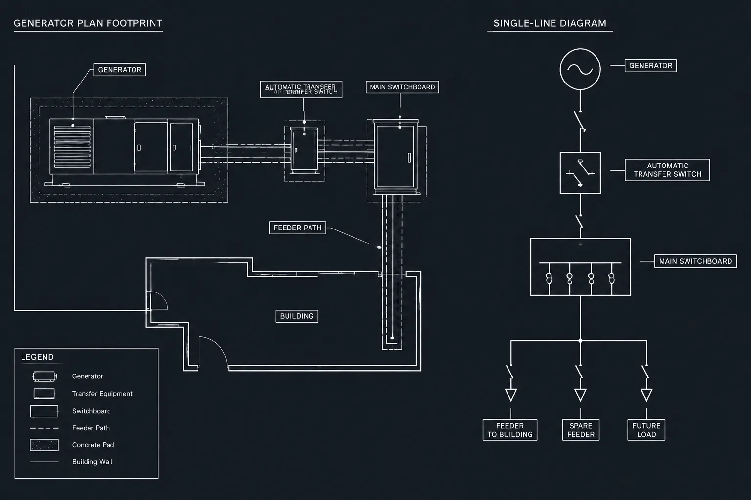
| Diagram symbol | Keep separate from plan quantities | A diagram may represent a system relationship rather than a physical count |
| Existing or demolition item | Report by status | Do not mix retained and removed work with new work |
| Future or spare provision | List separately when relevant | Differentiate installed equipment from reserved capacity or location |
| Reference-only symbol | Usually exclude | It may appear in a legend, detail, or background file |
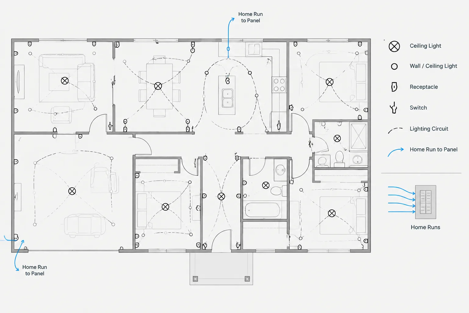
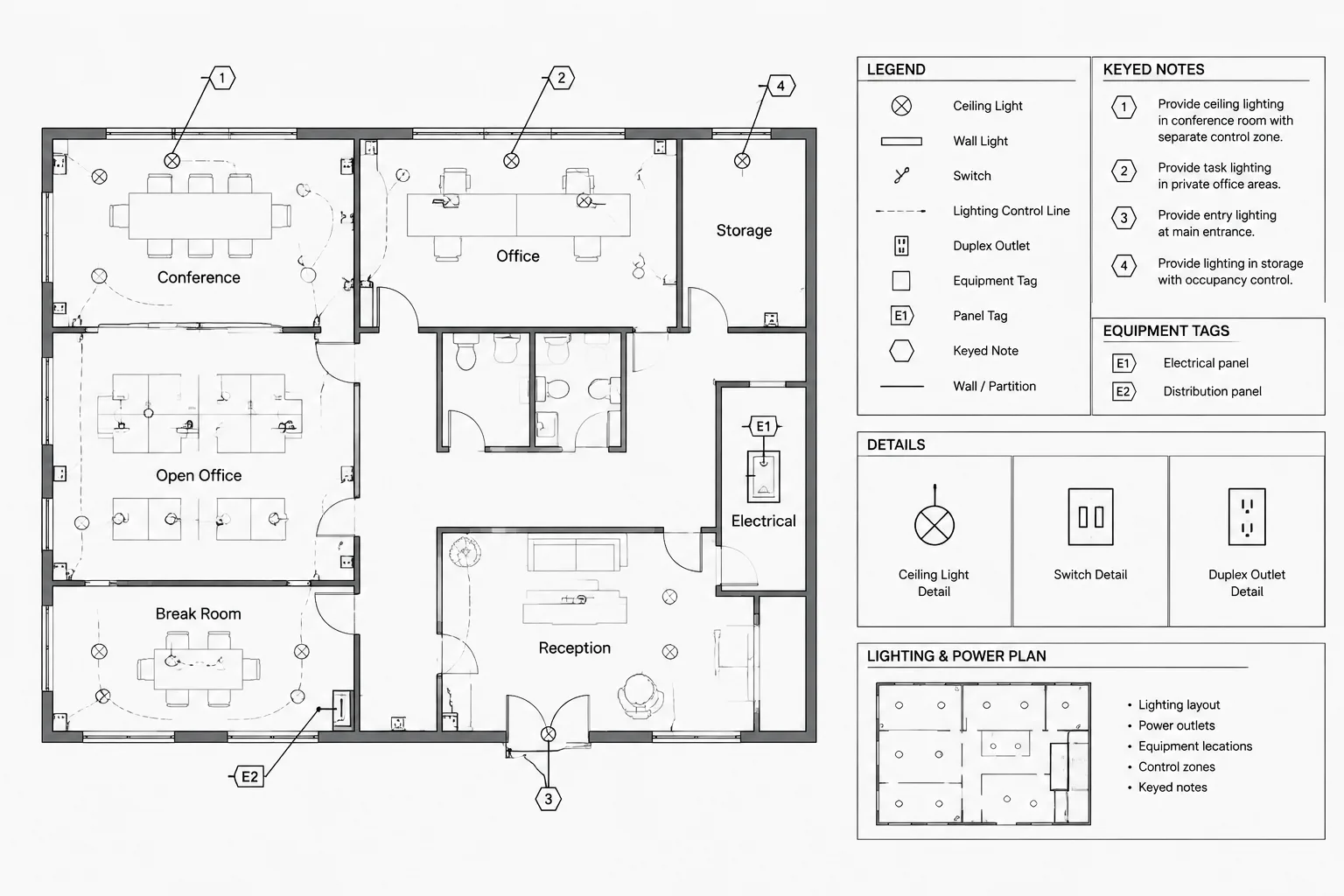
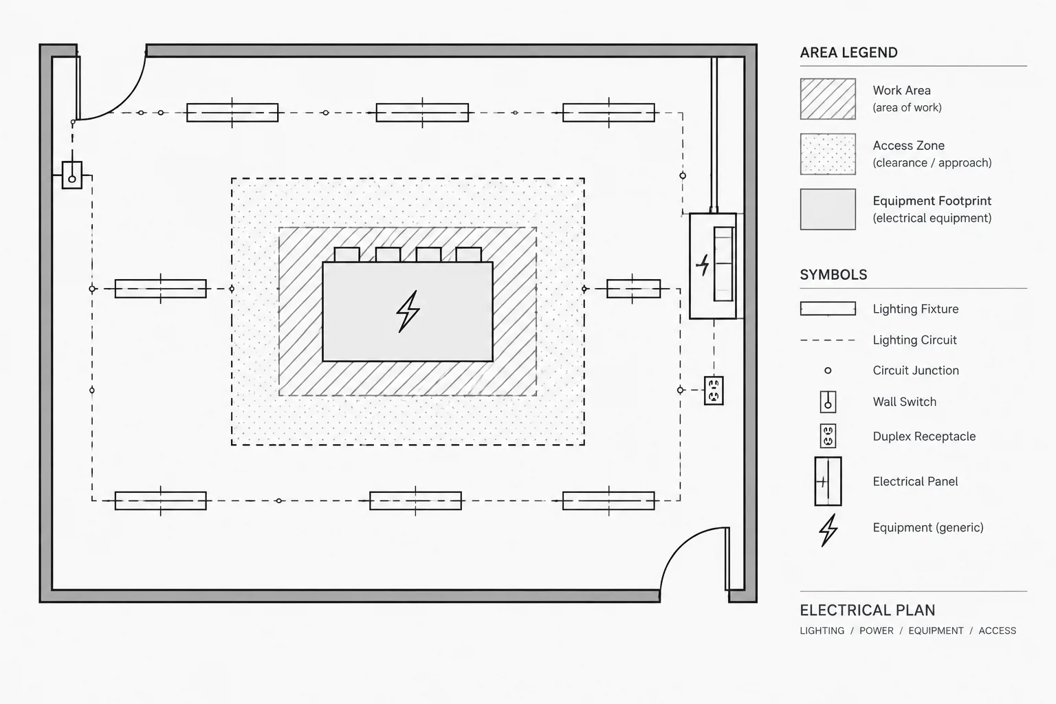
The project legend is the starting point, but it should not be the only reference. Compare block names, visible graphics, attributes, layer assignments, and nearby notes. Similar-looking symbols may represent different device types, while one device type may have several graphical variants.
Prepare the CAD view for a controlled count
Perform the review in a working copy or controlled review environment. Preserve the issued source files and avoid making untracked edits solely to simplify counting.
Control references and layers
Load the required external references and verify that the expected plan content is visible. Freeze or isolate background categories that are not part of the count, but document those visibility changes. A device placed on an unexpected layer can disappear when a normal layer filter is applied, so conduct a second review for electrical blocks on nonstandard layers.
Inspect model and sheet presentation
Determine whether the count is based on model-space content, sheet viewports, or both. Model space may contain design options, abandoned layouts, or geometry beyond the active viewport. Conversely, a sheet may intentionally hide part of a model or display an enlarged area through another viewport.
Use the issued sheet presentation to understand documented scope, then inspect the underlying CAD geometry to find duplicates, hidden alternatives, and misplaced symbols.
Check for nested and exploded content
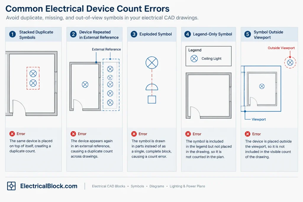
A device may be a standalone block, part of a nested room layout, or reduced to individual linework. Automated selection methods may count standalone blocks while missing nested or exploded symbols. Exploded graphics should be flagged for review because they may look correct on the plotted sheet but no longer carry usable identity or attribute data.
Use a two-pass counting workflow
A practical verification process combines a systematic quantity pass with a visual documentation pass.
Pass one: collect candidate quantities
Group devices by an identifier that remains meaningful across the project. Depending on the drawing structure, this may be a block name, device type attribute, fixture type, equipment tag, or a controlled combination of fields.
Record quantities by sheet and count zone rather than producing only a project-wide total. Subtotals make it easier to locate discrepancies later. Keep separate columns for new, existing-to-remain, relocated, demolished, alternate, and future items where those statuses occur.
Pass two: visually verify context
Review every count zone on the plotted plan or sheet layout. Confirm that each candidate symbol represents a device within the intended scope. Look for:
- Symbols placed directly on top of one another.
- Devices duplicated between the host drawing and an external reference.
- Symbols outside the viewport or beyond the project boundary.
- Devices copied into inactive design options.
- Plan symbols used only as legend examples.
- Missing or inconsistent type tags.
- Devices obscured by masks, hatches, or dense background geometry.
- Symbols that cross match lines or appear in more than one plan view.
Mark completed zones so that reviewers can distinguish checked areas from areas that are merely visible.
Reconcile counts with schedules and legends
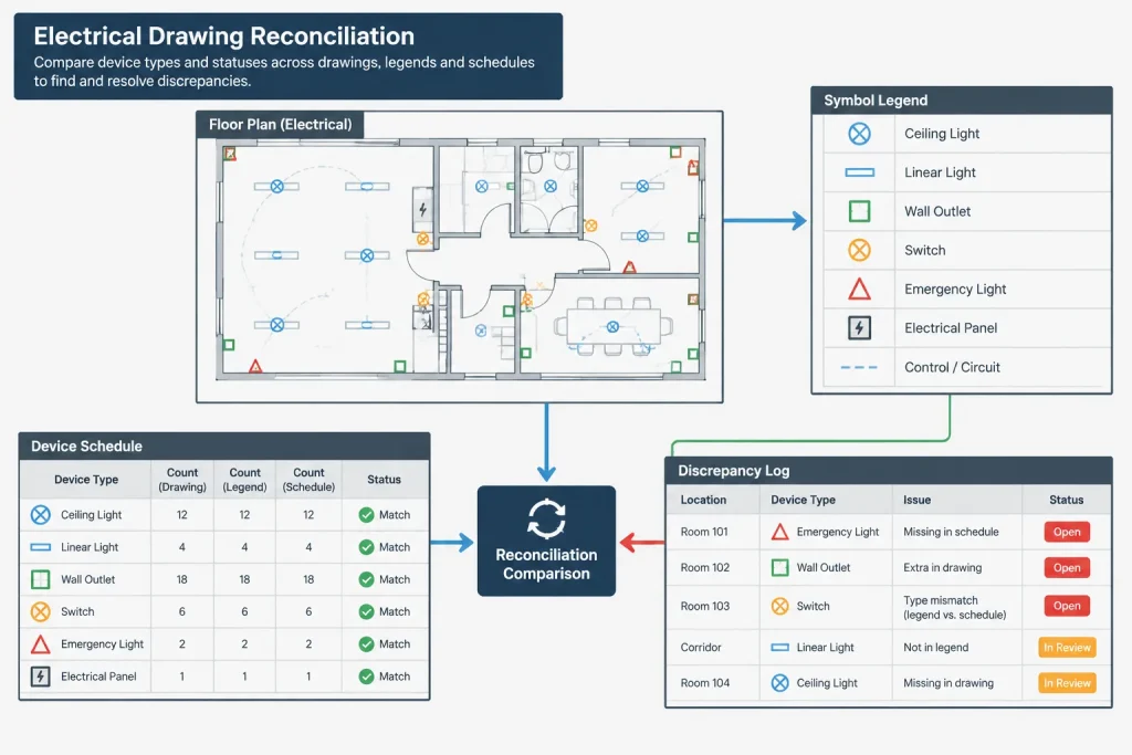
After the plan count is complete, compare it with the relevant drawing schedules. The schedule may organize devices by type, room, panel, system, or equipment identifier. Align the plan data with the schedule structure before comparing totals.
A discrepancy does not automatically mean that either source is wrong. It may reveal a documentation rule that requires clarification. For example, one schedule row may represent a family of related devices, or one plan symbol may represent a coordinated assembly.
Investigate discrepancies in this order:
- Confirm that the same project scope and revision are being compared.
- Check whether schedule rows and plan types use the same identifiers.
- Review demolition, alternate, future, and owner-furnished status.
- Look for typical layouts or quantity notes that replace individual symbols.
- Check enlarged plans, elevations, and details for duplicate representations.
- Identify untagged symbols and scheduled types with no plan instances.
Also compare the count list with the symbol legend. A legend type with no plan occurrence may be intentionally retained for a project phase, or it may be obsolete. A block found on the plan but absent from the legend is a documentation issue even when its quantity is known.
Track discrepancies instead of silently correcting totals
Maintain a discrepancy log during the review. Each entry should identify the sheet or file, count zone, device type, observed condition, and required resolution. Include a status such as open, clarified, corrected, or accepted.
A useful count record contains:
- Drawing issue or review date.
- Files and sheets included.
- Count boundary and exclusions.
- Device classification method.
- Quantities by type, status, sheet, or zone.
- Known assumptions.
- Unresolved discrepancies.
- Name or initials of the reviewer.
Do not overwrite uncertain quantities with an assumed answer. Report the plan count, schedule count, and unresolved difference separately until the design team confirms the intended documentation.
Repeat the verification after revisions
Device count verification is most useful when repeated at controlled milestones. After revisions, compare both the total quantity and the location of changes. An unchanged project total can conceal devices that were added in one area and removed in another.
Review revision clouds and marked changes, but do not rely on them as the only source of change information. Compare count-zone subtotals, device identifiers, and drawing status. Confirm that schedule revisions follow plan changes and that deleted symbols are not still represented in legends or equipment lists.
What a verified count does—and does not—prove
A verified count shows that the reviewer followed defined boundaries and reconciled the available drawing information. It does not prove that the design is complete, code-compliant, correctly installed, or suitable for procurement. Product selection, system design, installation requirements, and project applicability require review by the responsible professionals and project stakeholders.
For CAD quality control, the strongest result is a traceable count tied to specific sheets, zones, device identities, statuses, and revisions. That record is far more useful than a single unexplained total and provides a practical bridge between electrical plans, legends, schedules, estimates, and future drawing updates.
Turn the count into a traceable drawing record
The most defensible deliverable is not an isolated total. It is a reconciliation record that connects each quantity to a drawing area, device identity, work status, and source document. This structure allows reviewers to determine why a plan quantity differs from a schedule without repeating the entire count.
Separate identity from appearance
Graphic similarity is not enough to establish that symbols represent the same device type. Compare the visible symbol with its block definition, attributes, tag, layer, nearby notes, and legend description. Conversely, graphical variants may belong to the same scheduled type when the documentation explicitly connects them.
Preserve the basis of count
Record whether a quantity came from model geometry, an issued sheet view, a schedule, or a manual interpretation of a typical condition. When sources disagree, retain each observed result and document the reason for the difference rather than blending them into an unexplained total.
Use discrepancy categories consistently
Consistent categories make review comments easier to sort and resolve. Useful categories include:
- Identity issue: The symbol, tag, block name, or schedule designation does not align.
- Scope issue: The device belongs to a different phase, alternate, area, or work status.
- Representation issue: The same device appears in multiple views or referenced files.
- CAD structure issue: The object is hidden, nested, exploded, stacked, or placed on an unexpected layer.
- Documentation gap: A plan item lacks a legend or schedule relationship, or a listed type has no located plan instance.
A final review should distinguish confirmed quantities from unresolved drawing conditions. This prevents an apparently precise total from concealing assumptions that still require design-team clarification.
Frequently asked questions
Why can a CAD block count differ from the visible plan count?
A block query may include content outside active viewports, inactive options, reference examples, duplicate objects, or devices with a different work status. It may also miss exploded graphics, nested content, or symbols stored under unexpected definitions.
Should devices on enlarged plans be counted again?
Not automatically. Determine whether the enlarged plan documents the same devices shown on an overall plan or introduces separate scope. The count record should identify which view controls the quantity.
What should happen when the plan and schedule disagree?
Confirm that both sources represent the same revision, area, device classification, and work status. Record the separate quantities and the unresolved difference until the responsible project team clarifies the intended documentation.
Can the legend be used as the complete count list?
No. A legend explains drawing symbols but may include unused, reference, future, or phase-specific types. Plan occurrences, tags, schedules, notes, and scope boundaries must also be reviewed.
How should typical layouts be handled?
Identify the documented repetition rule and the locations where it applies. Do not multiply a representative layout without confirming its boundaries, exceptions, and relationship to individually drawn devices.
Does a verified device count confirm design compliance?
No. It confirms only that the stated counting and reconciliation process was performed against the identified drawing information. Design compliance, product suitability, procurement, and installation remain separate professional and project responsibilities.

Leave a Reply
You must be logged in to post a comment.