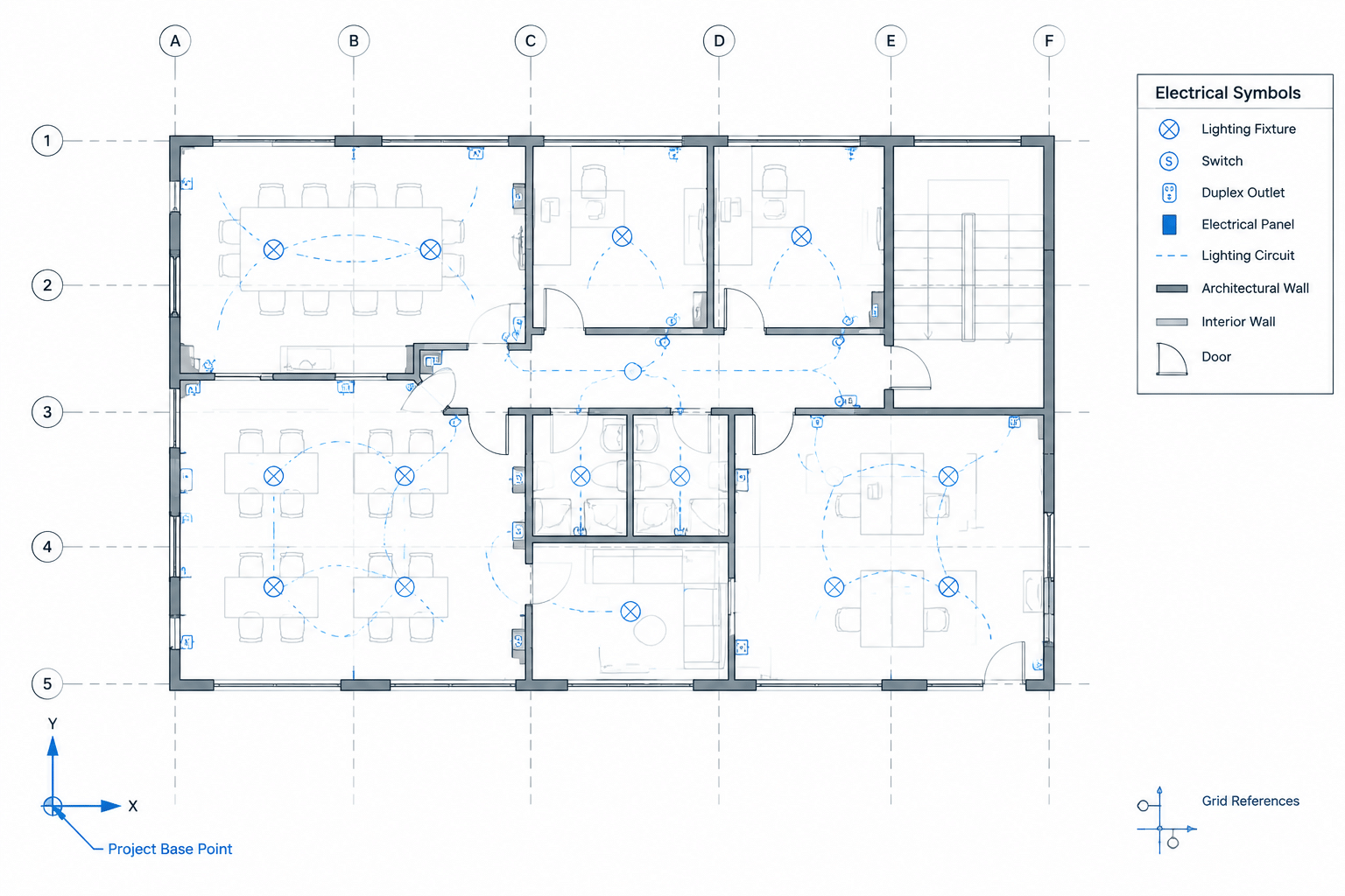
A drawing can look correctly coordinated while it is open and still contain a serious positioning problem. An architectural background may have been moved manually, an electrical plan may use a different origin, or a copied block may arrive far from the project geometry. These issues often surface when files are exchanged, backgrounds are updated, or multiple sheets are assembled.
A reliable electrical CAD coordinates workflow gives every discipline a consistent answer to a basic question: where does the project belong in model space? The goal is not merely to make the current view look right. It is to preserve repeatable alignment between electrical plans, architectural backgrounds, equipment layouts, site drawings, and consultant files.
Why coordinate problems are difficult to detect
Misalignment is not always obvious. A drafter can move an imported background until walls appear beneath the electrical symbols, then continue working without realizing that the file relationship has been broken. The drawing may plot correctly, but the next background update will not land in the same place.
Common warning signs include:
- A background must be moved, rotated, or scaled each time it is attached.
- Electrical symbols shift after an architectural file is replaced.
- Copied geometry appears far from the visible project.
- Two floor plans align visually but report unrelated coordinates.
- Site utilities and building plans cannot be overlaid consistently.
- Blocks insert at an unexpected size or location.
- Extents commands reveal isolated objects far from the main drawing.
These symptoms may come from different causes, so coordinate checking should address origin, rotation, units, reference method, and unwanted geometry separately.
Understand the main positioning concepts
Drawing origin
The drawing origin is the fixed coordinate reference from which model-space locations are measured. A building does not always need to sit close to that origin. Some projects use a shared project reference, while site and civil files may use real-world survey coordinates. The important requirement is consistency and documentation.
Project base point
A project base point is an agreed, recognizable location used to verify alignment. It might correspond to a structural grid intersection, a building corner, or another stable feature selected by the project team. It should not depend on temporary partitions, movable equipment, or an element likely to change during design.
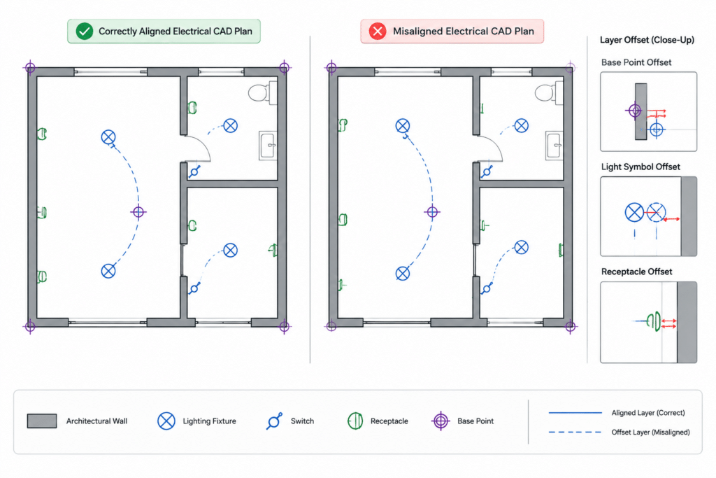
The base point does not necessarily replace the drawing origin. It provides a practical checkpoint: the same project feature should report the expected position in every coordinated file.
Rotation and orientation
Correct coordinates alone do not guarantee alignment. A background can share a base point but still use a different rotation. Project north, sheet orientation, and survey orientation may serve different presentation needs. Avoid rotating model geometry merely to make a plan fit neatly on a sheet. View and viewport controls are generally better places to manage sheet presentation.
Drawing units
Unit inconsistency can make a correctly shaped reference appear at the wrong scale. Before blaming coordinates, confirm the unit convention used by the source file, the host drawing, and reusable blocks. A coordinate workflow should record units alongside origin and rotation because all three affect the result.
Create a coordinate control record
A short coordinate control record helps prevent assumptions from becoming drafting errors. It can be kept in project CAD instructions, a setup drawing, or another controlled project document. The record should identify who established the reference and which file is considered authoritative.
| Control item | What to document | Why it matters |
|---|---|---|
| Authoritative background | The discipline and file used to establish project positioning | Prevents teams from aligning to different sources |
| Base-point description | A stable, recognizable project feature | Provides a repeatable visual check |
| Coordinate convention | Whether files use a local project reference or shared site coordinates | Clarifies why coordinate values may be large or offset |
| Orientation | The agreed model orientation and any separate sheet orientation | Reduces accidental rotation of model geometry |
| Units | The drawing-unit convention for backgrounds and blocks | Helps prevent scaling errors |
| Reference method | How backgrounds are attached and updated | Makes replacement predictable |
| Verification features | Additional grid intersections, corners, or site points used for checking | Detects rotation and scale errors that one point may miss |
Do not place sensitive survey information in general notes unless it is appropriate for the drawing set. The coordination record can remain part of the internal CAD workflow when necessary.
A practical electrical CAD coordinate workflow
1. Inspect the source before drafting
Review the architectural, structural, or site background before adding electrical work. Check its apparent units, orientation, visible extents, and relationship to its origin. Look for detached title blocks, old plan options, stray objects, or duplicated buildings that could distort the drawing extents.
2. Establish the authoritative reference
Confirm which model controls the building position. For an interior floor plan, this may be the current architectural model. For exterior feeders, utility routing, or site lighting, a coordinated site reference may also be required. Do not assume that separate source files already share the same coordinate system.
3. Attach backgrounds predictably
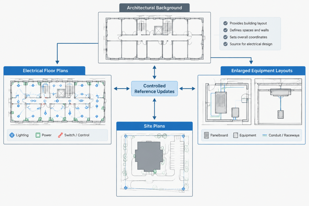
Use a documented insertion point, scale, and rotation rather than visually dragging a background into place. If a transformation is genuinely required, record it and apply it consistently. Avoid embedding an unexplained manual correction in every electrical sheet.
4. Verify more than one point
A single matching point proves only that one location coincides. Check additional features distributed across the project. If one point matches but another does not, investigate rotation, scale, or source geometry changes. Structural grids are particularly useful when they are stable and shared across disciplines.
5. Keep electrical geometry in its coordinated position
Place lighting symbols, receptacles, equipment outlines, home-run graphics, and routing information relative to the coordinated background. Do not move the entire electrical design to compensate for a sheet-layout issue. Paper-space viewports, clipping, and sheet composition should control presentation without changing model coordinates.
6. Test a background replacement
A sound setup should allow an updated background to replace the previous version without manual realignment. Perform an early replacement test rather than discovering the problem near an issue deadline. Review both general alignment and known design changes; a correctly positioned update can still contain relocated rooms or equipment.
Coordinate management for reusable CAD blocks
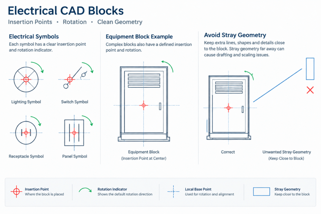
Project coordinates and block insertion points are related but not identical. A block should have a logical local insertion point even when it is used inside a large-coordinate project. For example, a device symbol may use its graphical center or connection point, while an equipment footprint may use a documented corner, centerline intersection, or service reference.
Before adding a block to a shared library, check that:
- The insertion point supports predictable placement and rotation.
- No hidden or stray geometry sits far from the block.
- The block follows the library unit convention.
- Its geometry was not copied with an unnecessary project-coordinate offset.
- Attributes and annotation remain associated with the intended symbol.
A poorly defined block can make cursor placement awkward, enlarge drawing extents, and create confusion when geometry is exported or exchanged.
Local building plans versus site-coordinate drawings
Large sites may involve both local building coordinates and a broader site coordinate system. These should not be mixed casually. A building electrical plan may prioritize clean internal coordination, while a site plan must align underground routing, utility points, exterior equipment, and other disciplines over a larger area.
If transformations between the systems are necessary, treat them as controlled project information. Keep the conversion method outside ordinary drafting improvisation, identify the authoritative files, and verify the result at several known features. Moving a building plan by eye onto a site drawing is not a dependable coordination method.
Quality-control checks before issuing drawings
- Reload or replace each major background and confirm that it retains alignment.
- Compare several known features across architectural, structural, and electrical files.
- Confirm that the electrical model has not been shifted to improve sheet composition.
- Check for unexplained scaling or rotation applied to referenced files.
- Review drawing extents for stray objects or distant block components.
- Confirm that model orientation and viewport orientation have not been confused.
- Verify that linked site and building information uses the documented relationship.
- Record intentional coordinate changes in the project revision workflow.
What to do when a background moves
Do not immediately move all electrical geometry to match. First determine whether the new file represents a legitimate project-coordinate change, an accidental shift, or a different export setup. Compare the current and previous backgrounds at stable project features and ask the source discipline to confirm the intended change.
If the project coordinate basis has officially changed, handle the correction as a controlled update. Preserve a copy of the prior state, document the transformation, move only the geometry that should follow the revised reference, and review annotations, enlarged plans, diagrams, and site connections afterward. Electrical documentation may include items that are graphically related to a plan but should not be transformed in the same way.
A stable foundation for coordinated drawings
Coordinate control is easy to overlook because it rarely appears as a prominent symbol or schedule on the finished sheet. Yet it supports nearly every electrical CAD activity, from placing devices on an architectural plan to coordinating feeders across a site.
A dependable workflow establishes an authoritative background, documents the base point and units, separates model position from sheet presentation, and verifies alignment at multiple locations. With those controls in place, electrical drawings can accept updated references without repeated manual correction—and CAD blocks, plans, and layouts remain where the project team expects them to be.


Leave a Reply
You must be logged in to post a comment.