
Abbreviations and acronyms help keep CAD drawings compact, but shortened terms are useful only when readers can interpret them consistently. A dedicated DWG reference can provide a controlled location for terminology used across plans, details, schedules, legends, and general notes.
This resource is intended to support drafting and documentation workflows. Before incorporating any reference table into a drawing set, compare its terminology with the project legend, office CAD standards, consultant requirements, and the language already used on related sheets.
Discover a comprehensive DWG file and CAD Block featuring essential abbreviations and acronyms used in architectural and engineering drawings. This downloadable resource streamlines your drafting process by providing a ready-made reference table, making it easy to standardize documentation and enhance communication in your CAD projects. Perfect for architects, engineers, and designers, this DWG file is fully compatible with AutoCAD and other major CAD software. Improve workflow efficiency and accuracy by integrating these abbreviations and acronyms directly into your construction plans or technical drawings.
Please log in or register to download this file.
Why abbreviation control matters in CAD drawings
Architectural and engineering drawings often have limited annotation space. Abbreviations reduce visual clutter, but inconsistent shorthand can create uncertainty during coordination and review. The same letter group may carry different meanings across electrical, architectural, mechanical, structural, and civil documents.
A centralized reference helps drafters use the same term throughout a drawing set. It also gives reviewers a practical place to confirm intended meanings instead of interpreting each note from context.
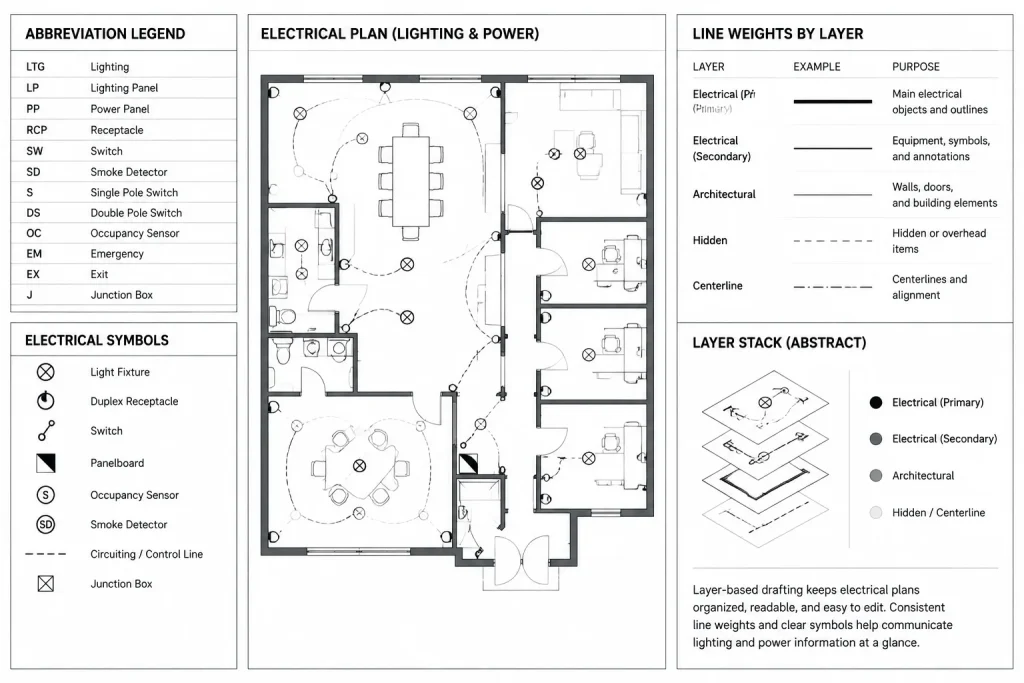
How to use an abbreviation reference in a DWG workflow
After opening or inserting the reference, review its text, layers, text styles, and overall organization before placing it in a production file. Confirm that the content remains legible at the intended plotted scale and that it follows the project’s annotation conventions.
The reference may be kept in a dedicated legend area, incorporated into general notes, or adapted for a project-specific sheet. Placement depends on the drawing set structure and the documentation practices used by the design team.
Recommended drafting checks
- Compare terminology: Check each retained entry against the language used in plans, diagrams, details, and schedules.
- Remove conflicts: Avoid using the same abbreviation for unrelated terms within the same drawing set.
- Coordinate disciplines: Review abbreviations that appear on both electrical drawings and consultant backgrounds.
- Match CAD standards: Align layers, text styles, linework, and title formatting with the destination file.
- Confirm readability: Inspect the table in the intended sheet layout rather than relying only on model-space appearance.
- Control revisions: Update the reference whenever project terminology changes so that the legend and drawing notes remain synchronized.
Abbreviations, acronyms, and drawing symbols
An abbreviation is a shortened form of a word or phrase. An acronym is formed from initial letters and may be read as a word or as individual letters. A drawing symbol is different: it uses a graphic mark to represent equipment, a device, a connection, or another documented condition.
These elements often appear together in electrical legends. The graphic symbol identifies the object, while adjacent text provides a designation or description. Keeping those elements coordinated is especially important on lighting plans, power plans, equipment layouts, panel documentation, and single-line diagrams.
Building a project-specific reference
A general CAD block is best treated as a starting point rather than an automatic authority for every project. Retain only terminology that is relevant to the drawing set, and define any office-specific or project-specific shorthand that a reader might not recognize.
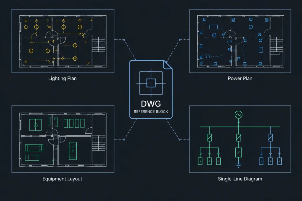
When adapting the reference, useful information fields may include the shortened term, its written meaning, the applicable discipline, and an optional clarification note. Consistent sorting and formatting make the finished legend easier to scan during design reviews and sheet coordination.
Relationship to other CAD documentation
Abbreviation management is closely connected to symbol legends, annotation standards, CAD layer organization, title blocks, general notes, and sheet coordination. Reviewing these elements together helps prevent a term from being defined one way in a legend and used differently elsewhere in the same drawing package.
Frequently asked questions
Are drawing abbreviations universal?
No. Many terms are widely recognized, but meanings can vary by discipline, organization, region, and project. The project legend and approved documentation conventions should control how a term is interpreted.
What is the difference between an abbreviation and an acronym?
An abbreviation is any shortened form of a term. An acronym is created from initial letters. In everyday CAD documentation, both are often collected in the same reference or legend.
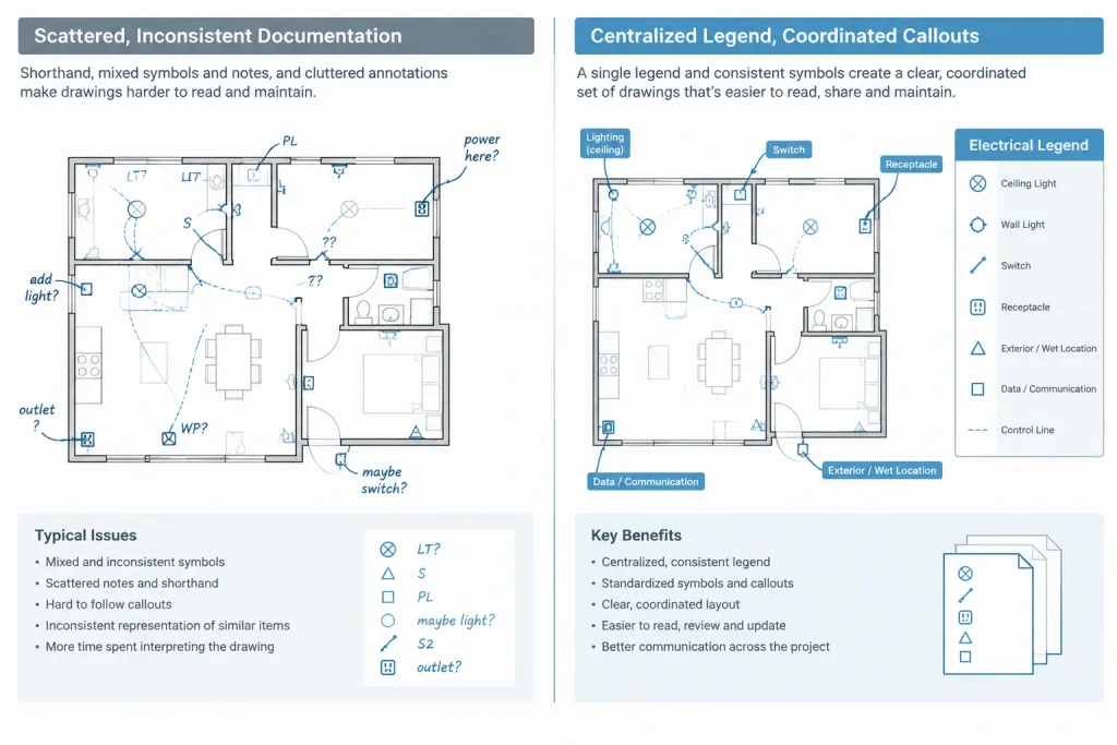
Where should an abbreviation table be placed?
It may appear in a general notes area, a dedicated legend sheet, or another controlled location within the drawing set. The best location is one that remains easy to find and consistent with the project’s sheet organization.
Should every available abbreviation be included?
Not necessarily. A focused list of terms actually used in the drawing set is usually easier to review than a large collection containing unrelated entries. Remove unused content unless the governing documentation procedure requires otherwise.
What should be checked after inserting the DWG content?
Review terminology, layers, text styles, annotation behavior, visual hierarchy, and plotted readability. Also check for duplicate definitions or conflicts with existing legends and consultant drawings.
Can the reference replace project review?
No. The reference supports drafting efficiency, but terminology should still be verified by the responsible design and documentation team before issue.




Leave a Reply
You must be logged in to post a comment.