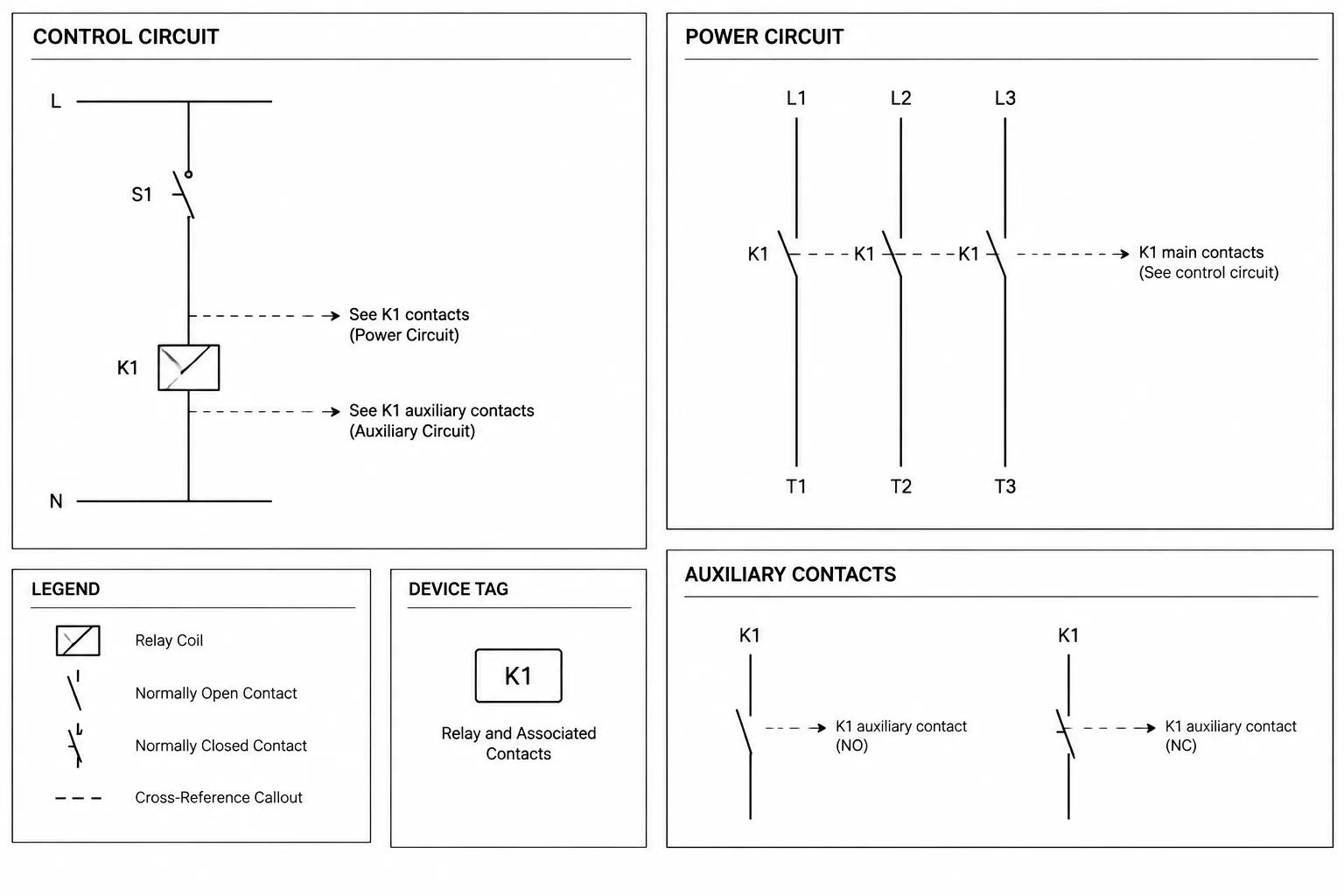
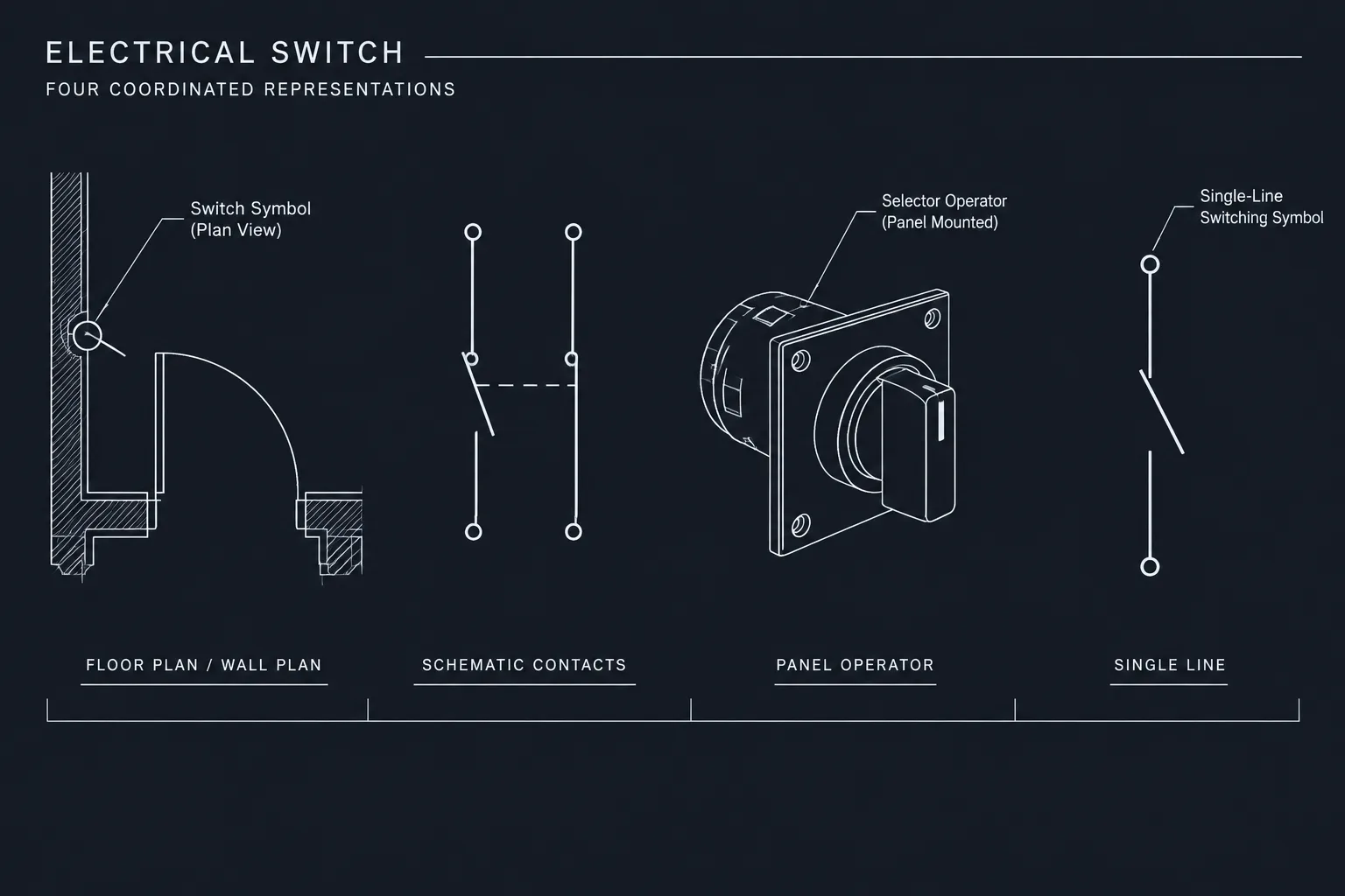
Relay and contactor symbols often represent relationships that extend beyond a single schematic location. A readable drawing set must connect each distributed contact to its controlling coil while keeping device identity separate from sheet, rung, zone, or coordinate information.
This reference explains how to structure those relationships in CAD using stable device tags, consistent symbol attributes, clear location references, and repeatable quality-control checks. The emphasis is on drafting and document coordination rather than device selection, field installation, or project-specific electrical design.
A relay or contactor may appear simple as a physical component, but its representation can be distributed across several locations in an electrical drawing set. The coil may be shown on one schematic sheet, while associated contacts appear on other rungs, control circuits, or interconnection diagrams. Without a consistent cross-reference method, reviewers must search the drawings to determine which symbols belong to the same device.
Effective relay and contactor cross-references in CAD connect these separated symbols through a shared device designation and clear location references. The objective is not merely to label symbols. It is to make the operating relationship traceable without drawing unnecessary wires across the page or relying on undocumented assumptions.
Why coils and contacts are shown separately
Control schematics are usually organized around circuit logic rather than the physical shape of each component. A coil is placed where it is energized in the circuit, and each associated contact is placed where it changes another circuit condition. One device can therefore have symbols in several drawing zones or on several sheets.
This distributed representation keeps signal paths readable, but it introduces documentation questions:
- Which contacts are operated by a particular coil?
- Where is the controlling coil shown?
- Are all expected contacts documented?
- Does a contact designation appear more than once by mistake?
- Has a drawing revision moved a symbol without updating its reference?
A well-structured CAD workflow answers these questions through device tags, contact identifiers, and location references.
Start with a stable device designation
The coil and all associated contacts should carry a common device designation. The exact naming pattern depends on the project, client, equipment supplier, and drawing convention. A designation might identify a relay, contactor, timer, or another control device, but its most important property is uniqueness within the defined drawing scope.
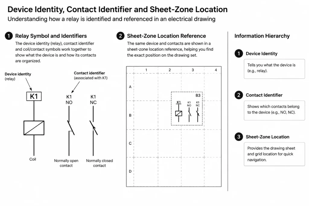
Before drafting, decide where uniqueness applies. A tag that is unique on one sheet may still conflict with the same tag on another sheet. For multi-sheet control packages, a drawing-wide, panel-wide, or project-wide convention is generally easier to audit than isolated sheet numbering. The selected scope should be documented so that a reviewer understands whether identical tags represent the same device or separate devices.
A useful device designation should remain stable when the symbol moves. Avoid building a tag entirely from its current rung or drawing-zone location if normal revisions are likely to change that location. Location information can be shown separately and updated without renaming the device itself.
Separate identity from location
Device identity and drawing location perform different functions:
- Device designation: Identifies which physical or functional device the symbol represents.
- Contact identifier: Distinguishes individual contacts associated with that device when necessary.
- Location reference: Directs the reader to the sheet, zone, rung, or coordinate where the related symbol appears.
- Function text: Describes the device purpose when the tag alone is not informative.
Keeping these fields separate improves revision control. A coil can move to another sheet while retaining its device designation. Only the cross-reference location needs to change.
Common ways to display cross-references
There is no single layout that fits every schematic package. The best format is the one used consistently and explained in the drawing legend or notes.
| Method | Typical use | Drafting consideration |
|---|---|---|
| Sheet and zone reference | Multi-sheet schematics with drawing grids | Zone labels must remain visible and stable after sheet revisions. |
| Sheet and rung reference | Ladder-style control diagrams | Rung identifiers must be unique enough to prevent ambiguous results. |
| Coordinate reference | Drawings using border coordinates | References should point to a practical search area, not an overly broad region. |
| Contact list beside the coil | Compact circuits or device-centered documentation | The list must be updated whenever contacts are added, removed, or relocated. |
| Coil reference beside each contact | Widely distributed contacts | Text placement should not be confused with wire numbers or terminal labels. |
Some drawing sets combine methods, such as showing a coil location beside each contact and a contact summary beside the coil. This can be helpful on complex projects, but duplicate information creates an additional coordination obligation. Every displayed reference must agree.
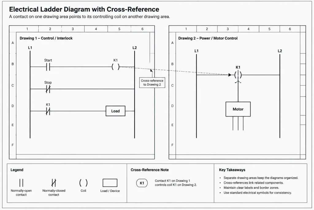
Build the CAD symbol as coordinated data
A coil block and a contact block should be treated as related members of one documentation system, not as unrelated graphics. Even in a basic CAD environment, consistent attributes or structured text fields can support that relationship.
Useful coil symbol fields
- Device designation
- Functional description
- Associated contact references
- Equipment, enclosure, or panel identifier when relevant
- Drawing status or revision information if included in the project workflow
Useful contact symbol fields
- Parent device designation
- Individual contact identifier where required
- Contact state representation
- Coil location reference
- Functional note when the contact purpose is not obvious from the circuit
Attribute names should be standardized across the symbol library. If one contact block uses a field called parent device and another stores the same information as relay number, automated checks and data extraction become harder. Internal field naming can be more structured than the visible annotation, provided the plotted result remains clear.
Show contact state consistently
Contact symbols must be interpreted according to the documented drawing convention. The set should state the condition in which contacts are represented, such as the normal condition of the control device or another clearly defined system state. Do not assume every reader will infer that convention from the symbol shape alone.
Keep symbol geometry, state labels, and descriptive text distinct. A note describing an operating sequence should not visually alter the basic contact symbol. When unusual operating conditions matter, explain them through notes, sequence descriptions, or dedicated diagrams rather than creating an undocumented symbol variation.
A practical drafting workflow
- Define the tag structure. Establish how devices are identified and where uniqueness applies.
- Place the controlling coil. Add the stable device designation and functional description.
- Place associated contacts. Assign each contact the same parent designation and any required individual identifier.
- Add location references. Point contacts to the coil and, when the documentation method requires it, list contacts near the coil.
- Check symbol state. Confirm that contact graphics and descriptions follow the drawing convention.
- Review text hierarchy. Make device tags easy to distinguish from wire numbers, terminals, cable identifiers, and notes.
- Run a relationship check. Verify that every referenced device exists and that every distributed contact has an identifiable parent.
- Recheck after layout changes. Moving a circuit between sheets or zones can invalidate references even when the electrical logic is unchanged.
CAD layout practices that improve readability
Place the device designation close enough to the symbol that ownership is obvious, but avoid crowding conductors or connection points. Use a predictable text position for similar symbols. If contact references are listed beside a coil, align them as a compact group rather than scattering them around the circuit.
Cross-reference text should have a distinct visual role. It may be smaller or arranged differently from the primary device tag, but it must remain legible at the plotted sheet scale. Test the plotted PDF rather than judging only from a zoomed CAD view.
Use layers according to project needs, but do not place essential cross-reference text on a layer that is routinely frozen in schematic viewports. If reference information is optional for certain outputs, document the layer-state workflow so it is not accidentally omitted from an issue set.
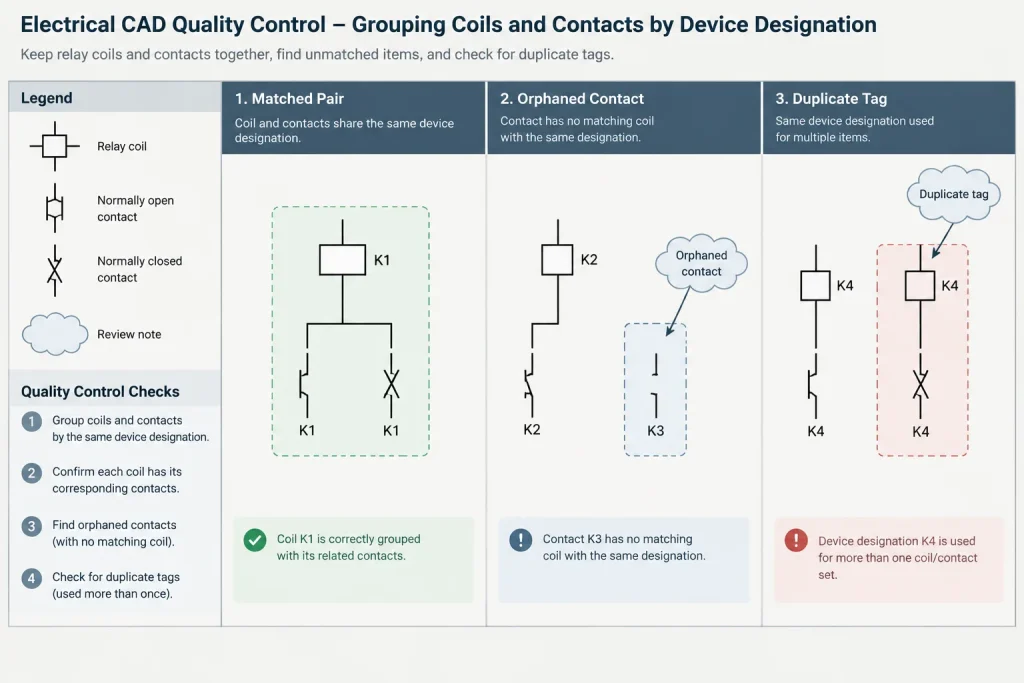
Quality-control checks for distributed devices
A focused device audit can detect errors that a general visual review may miss. Check for:
- Contacts with no matching coil designation
- Coils referenced by contacts but absent from the drawing set
- Duplicate device tags assigned to unrelated devices
- Duplicate contact identifiers under the same parent device
- References pointing to obsolete sheets, zones, or rungs
- Coil contact lists that disagree with symbols placed elsewhere
- Inconsistent normally open or normally closed graphics
- Device tags that differ only because of spacing, punctuation, or text case
- Cross-reference text hidden by masks, linework, or viewport clipping
Data extraction can assist with this review when blocks contain consistent attributes. A simple device list can group symbols by parent designation and reveal unmatched or duplicated entries. The extracted results should still be checked against the plotted drawings because correct data does not guarantee clear presentation.
Coordinate with other drawing types
A control-schematic device tag may also appear on panel layouts, equipment elevations, wiring diagrams, terminal drawings, or connection schedules. Preserve the same identity where those references describe the same device. If another drawing uses a different naming convention, provide an explicit mapping rather than silently changing the designation.
Relay and contactor cross-referencing is ultimately an information-management task. Clean symbols matter, but the greater value comes from maintaining dependable relationships among coils, contacts, locations, and related documents. A consistent CAD structure makes control logic easier to review, revise, and hand off without implying that the drawing has been verified for a particular installation. Project-specific design requirements and device documentation still require qualified review.
Using the cross-reference system during drawing review
A useful review begins with relationships rather than individual symbol appearance. Select a device designation, locate its controlling coil, identify every contact assigned to that parent, and compare the displayed references with the actual drawing locations. This approach helps distinguish a graphical issue from a data-coordination issue.
Review identity and location independently
- Identity review: Confirm that the coil and contacts use the same parent designation and that the tag is not assigned to an unrelated device.
- Location review: Confirm that every sheet, zone, rung, or coordinate reference still points to the current symbol position.
- Presentation review: Check that tags and references remain legible and cannot be mistaken for wire, terminal, or cable identifiers.
- Logic review: Confirm that symbol states and functional descriptions follow the convention documented for the drawing set.
This separation is especially helpful during revisions. A moved contact may retain the correct device identity while carrying an obsolete location reference. Conversely, a location may be correct even though the symbol was assigned to the wrong parent device.
Support reliable CAD handoffs
Cross-reference information should remain understandable when drawings move between designers, software workflows, plotted outputs, and downstream documentation. Visible annotations are important, but the underlying block attributes or structured fields should also use consistent names and values.
Before issuing a drawing package, compare the plotted sheets with any extracted device list. Data extraction can identify missing or duplicated relationships, while the plotted review reveals clipped text, hidden layers, crowded labels, and references that are technically present but difficult to interpret.
If a project changes its tag format or drawing-location method, document the transition and update related drawings together. Mixing old and new conventions without an explicit mapping can make identical devices appear unrelated or make separate devices appear connected.
Frequently asked questions
What is the difference between a device tag and a cross-reference?
A device tag identifies the relay, contactor, or other control device. A cross-reference identifies where a related symbol is located in the drawing set. Keeping these functions separate allows a symbol to move without requiring the device itself to be renamed.
Should every contact show the coil location?
That depends on the documented drawing convention. For widely distributed contacts, a coil location beside each contact can reduce searching. If the drawing instead uses a contact summary near the coil, that method should be applied consistently and explained in the legend or notes.
What should be updated when a circuit moves to another sheet?
Update every location-dependent reference associated with the moved symbols. The stable parent device designation should normally remain unchanged unless the device identity or documented naming scope also changes.
Can matching text alone establish a reliable parent-child relationship?
Matching visible text helps readers, but structured block attributes provide a more dependable basis for data extraction and automated checks. The visible annotation and stored attribute values must agree.
How should contact availability be documented?
Do not infer available contacts from a generic symbol. Coordinate the schematic with the selected device documentation and the project design requirements. The CAD cross-reference system should report documented relationships rather than imply unsupported device capabilities.
Do cross-references replace normal circuit tracing?
No. Cross-references help readers navigate between related symbols, but they do not replace conductor paths, terminal information, connection documentation, or a qualified review of the control logic.
Leave a Reply
You must be logged in to post a comment.