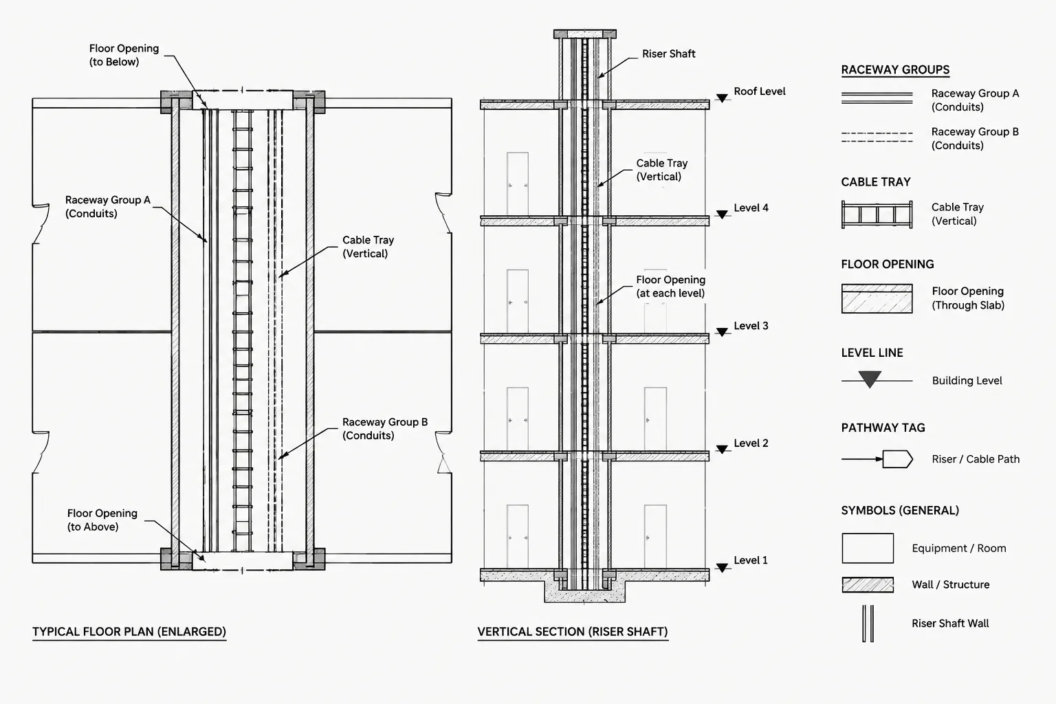
Electrical riser shaft drawings translate vertical distribution concepts into coordinated building geometry. They help CAD users connect pathway information from electrical plans and diagrams with shaft boundaries, floor interfaces, structural conditions, and access locations at each level.
The following reference explains how to organize shaft plans, sections, tags, layers, and cross-references without treating schematic routing or generic details as finalized construction information. Project backgrounds, pathway arrangements, openings, and interfaces still require discipline coordination and review by the responsible design team.
Electrical riser shaft drawings document the physical space used by feeders, raceways, busway, cable tray, grounding conductors, and related equipment as they pass between building levels. Unlike an electrical riser diagram, which explains system relationships schematically, a shaft drawing shows where those systems fit within the building.
A useful shaft package connects diagrammatic intent with architectural and structural geometry. It helps the project team understand pathway locations, floor openings, transitions, access conditions, and potential conflicts. The drawings must remain coordinated with the electrical plans, single-line diagram, equipment schedules, and other disciplines without implying that a generic CAD detail is automatically suitable for construction.
Riser Shaft Drawing vs. Riser Diagram
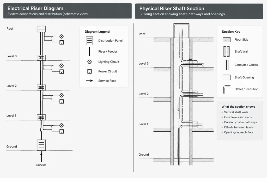
The terms are sometimes used interchangeably, but the drawings serve different purposes.
| Drawing type | Primary purpose | Typical content |
|---|---|---|
| Riser diagram | Shows system topology and vertical distribution relationships | Sources, equipment, feeders, branches, system levels, and diagrammatic connections |
| Shaft plan | Shows the physical arrangement at a specific floor | Shaft walls, pathways, openings, equipment footprints, access points, and nearby construction |
| Shaft section or elevation | Shows vertical continuity through multiple levels | Floor lines, pathway runs, offsets, supports, transitions, and level references |
| Opening or penetration detail | Clarifies a localized interface with construction | Opening boundaries, pathway arrangement, sleeves where applicable, and references to approved sealing details |
A schematic riser can show that a feeder extends from one floor to another, but it generally cannot demonstrate whether the physical route fits beside other services. Conversely, a shaft section may show several raceways passing through floors without fully explaining their electrical source and destination. Both forms of documentation are needed when vertical distribution is complex.
Start with a Coordinated Background
Build the CAD view from current architectural and structural backgrounds. At minimum, the working view should identify shaft boundaries, floor slabs, structural framing, nearby rooms, doors or access panels, and relevant ceiling or service zones.
Do not assume that shaft geometry is identical on every floor. Walls may shift, slabs may contain different openings, beams may cross the route, and the shaft may terminate or change configuration. Review each level rather than copying one typical plan throughout the drawing set.
Use external references or another controlled background workflow so architectural changes can be incorporated without redrawing the building. Keep electrical geometry on discipline-specific layers, and avoid placing electrical pathways directly into the architectural reference file.
Establish a Floor-by-Floor Reference System
Each shaft plan should be tied to an identifiable building level and drawing location. A reader must be able to move between the overall electrical plan, enlarged shaft plan, vertical section, and system diagram without guessing which area is being shown.
- Use a consistent shaft identifier across all sheets.
- Label every floor or level shown in a section or elevation.
- Place enlargement callouts on the overall plans.
- Reference the section or elevation from the related shaft plan.
- Use pathway tags that agree with schedules and diagrams.
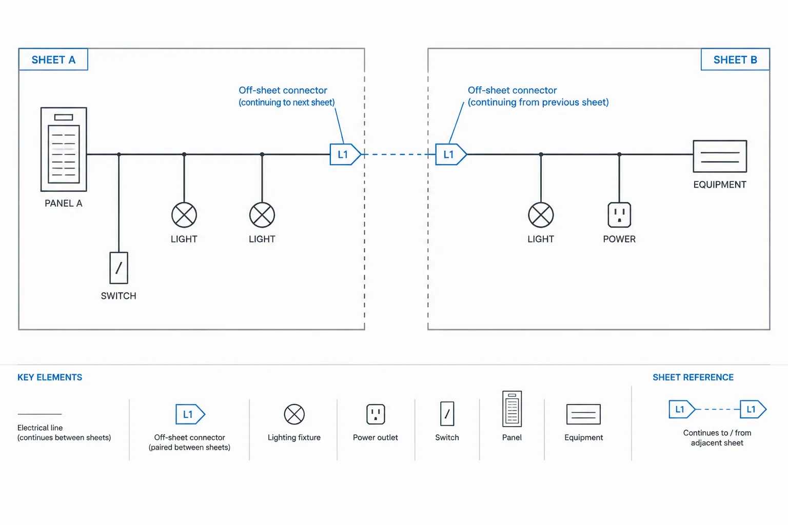
- Indicate continuation destinations when a route leaves the displayed view.
If a shaft serves more than one electrical system, identifiers should distinguish the pathways without relying solely on line color. Colors can be useful while drafting, but plotted drawings also need readable tags, line patterns, notes, or other reproducible graphic differences.
Draft the Shaft Plan Before the Vertical View
The plan view establishes the physical arrangement at each floor. Draw the architectural shaft boundary from the coordinated background, then add the electrical pathways and equipment that occupy the space.
Show actual pathway positions
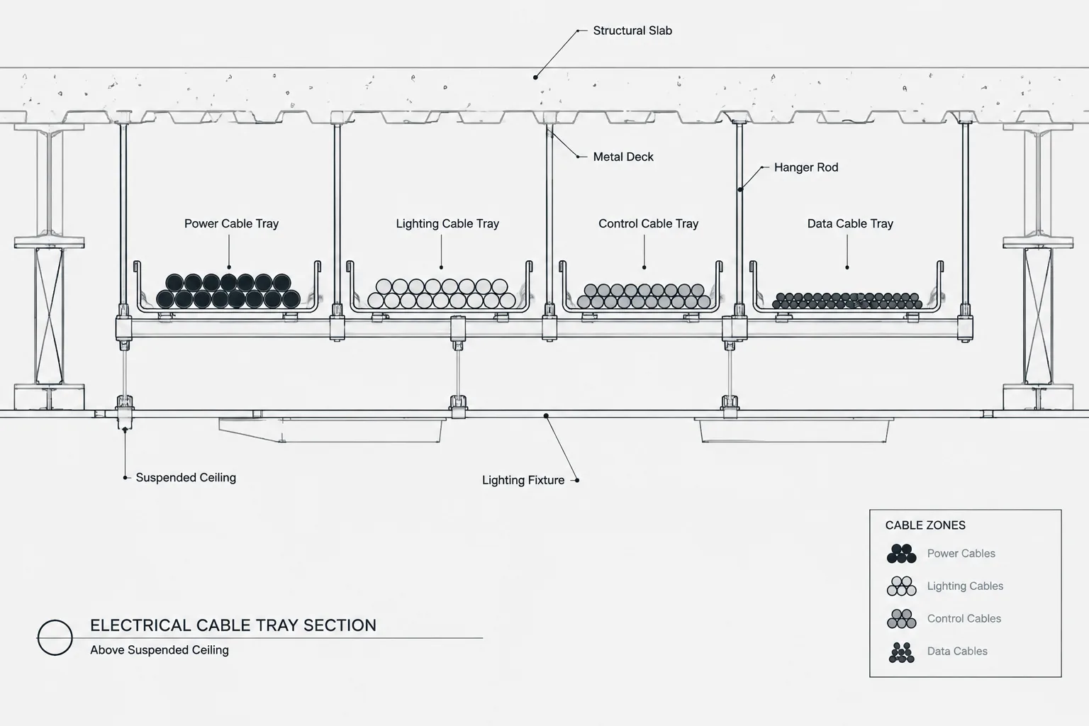
Represent raceway groups, busway, and cable tray with a consistent graphic method. A single centerline may be appropriate for an overall coordination plan, while an enlarged shaft plan may require pathway outlines or grouped envelopes. State the representation method in the legend or notes so users do not mistake a symbolic line for a physical edge.
Identify openings and interfaces
Show where pathways pass through slabs, walls, or other construction. Opening geometry should remain distinguishable from the pathway itself. If the structural drawing controls the final opening, use a clear reference rather than presenting an unverified electrical opening as finalized construction information.
Document access conditions
Include doors, access panels, removable construction, or adjacent service areas when they affect how equipment and pathways are reached. Access and working-space requirements must come from the project criteria and applicable review, not from an assumed generic CAD block.
Retain nearby coordination geometry
Show enough surrounding construction to explain the shaft location. Nearby walls, corridors, electrical rooms, and major services may be relevant, but excessive background detail can obscure the pathways. Screen or simplify secondary geometry while preserving critical interfaces.
Create a Vertical Section or Elevation
After the floor plans are established, create a vertical view that aligns the pathways through the building. Begin with floor lines and level names, then add shaft boundaries and the principal vertical routes.
The vertical view should make changes visible. Show offsets, bends, transfer conditions, terminations, and transitions to horizontal routing. Avoid drawing a continuous straight run when the floor plans show that the route changes position.
Use break lines carefully if part of the shaft is omitted. A break should save space without hiding an important transition. If several floors are genuinely repetitive, a typical condition can be used, but exceptions should receive separate plans or details.

Coordinate plan and section geometry
A pathway shown on one side of the shaft in plan should appear in a compatible position in the section. Perfect projection may not always be possible when the section is diagrammatically simplified, so note any deliberate simplification. Unexplained inconsistencies can lead readers to treat two views as different routing instructions.
Use Tags Instead of Repeating Long Notes
Pathway tags are more reliable than repeatedly typing descriptions beside every line. A tag can point to a raceway schedule, feeder schedule, cable tray schedule, or keyed note containing the controlled information.
A practical tag may communicate:
- A unique pathway or group identifier
- Origin and destination references
- System classification
- Associated schedule or diagram reference
- Status such as existing, new, or future when applicable
Keep the same identifier through plans, sections, diagrams, and schedules. If one drawing uses a feeder tag while another uses an unrelated raceway tag, provide an explicit relationship between them rather than expecting the reader to infer it.
Separate Drawing Information with Purposeful Layers
Layering should support editing, plotting, and review. A shaft drawing may benefit from separate layers for pathway outlines, centerlines, openings, equipment, supports shown diagrammatically, tags, level annotations, references, and background geometry.
Do not create a separate layer for every individual pathway unless the project workflow has a clear need for that level of control. Excessive layer fragmentation makes visibility management difficult. Organize layers by graphic purpose, system, status, or another documented project convention.
Use lineweight hierarchy to distinguish the shaft boundary, electrical routes, secondary construction, and annotation. Hatches should be limited to areas where they explain an opening, reserved zone, or construction condition; dense hatching can make tags and pathway lines difficult to read.
Coordinate with Other Disciplines
Vertical electrical space often competes with mechanical piping, plumbing, fire protection, structural framing, and architectural access requirements. The CAD drawing should support coordination without attempting to replace the responsible discipline’s documents.

- Compare floor openings with structural plans and current coordination models or drawings.
- Check pathway offsets against beams and slab edges.
- Review shared shaft areas for crossing services.
- Confirm that doors and access panels remain represented correctly.
- Reference project-approved penetration and sealing details rather than inventing a generic assembly.
- Flag unresolved conflicts with review notes that are removed or resolved before issue.
When backgrounds disagree, do not force the electrical route to match one file silently. Record the discrepancy and identify which source controls the next revision.
Common Drafting Problems
Copying a typical floor without checking exceptions
Repeated levels can reduce drafting effort, but small architectural or structural differences may affect the route. Compare every level before assigning a typical designation.
Showing openings with no ownership or reference
An unlabeled rectangle may be interpreted as a finalized slab opening, a sleeve group, or merely a clearance envelope. Name the graphic and reference the controlling drawing or detail where appropriate.
Using a riser diagram as a physical layout
Diagram spacing is normally selected for clarity, not construction geometry. Do not scale locations or infer shaft arrangements from a schematic riser.
Losing identifiers between views
A pathway that changes names between the plan and section becomes difficult to trace. Maintain stable tags and document intentional identifier changes.
Hiding transitions behind annotation
Leaders, tags, and notes should not cover offsets or intersections. Use annotation zones and move labels away from dense pathway geometry.
Final CAD Review Checklist
- Verify the architectural and structural backgrounds are current.
- Confirm the shaft identifier and level names across all views.
- Trace every principal pathway from its origin to its destination.
- Compare pathway positions between plans and vertical views.
- Check openings, transitions, offsets, and terminations.
- Confirm tags agree with diagrams and schedules.
- Review lineweights, screening, and text at the intended plot scale.
- Remove temporary coordination notes and unresolved drafting artifacts.
- Identify details or dimensions that still require project-specific verification.
Well-organized electrical riser shaft drawings make vertical distribution understandable as both a system and a physical installation concept. Their value comes from coordinated views, stable references, controlled annotation, and transparent handling of unresolved conditions—not from adding unnecessary graphic detail.
Managing Revisions Across the Shaft Drawing Package
A shaft package should be reviewed as a connected group of views rather than as independent drawings. A change to a pathway position on one floor may affect the enlarged plan, vertical section, opening information, system diagram, schedule references, and adjacent-discipline coordination.
When incorporating a revision, begin by identifying every view that uses the affected shaft or pathway tag. Update the physical geometry and then check whether the change alters a continuation reference, opening boundary, offset, access condition, or destination note. Stable identifiers make this review faster because the same route can be traced throughout the drawing set.
Distinguish design changes from background changes
An updated architectural or structural reference may move a wall, floor edge, framing element, or access point without changing the intended electrical system relationship. Keep those background revisions distinguishable from deliberate electrical rerouting so reviewers can understand why the shaft drawing changed.
Keep unresolved conditions visible during coordination
Potential conflicts should remain clearly marked in working files until the project team resolves them. Avoid adjusting geometry merely to make the view appear coordinated when the controlling condition is still uncertain. Before issue, replace temporary coordination graphics with the approved route, an appropriate reference, or a clearly documented project-specific note.
Check the plotted result
Model-space organization alone does not confirm that a drawing communicates successfully. Review the sheet output to ensure pathway groups remain distinguishable, level references are legible, background screening is effective, and tags do not conceal transitions. Also confirm that external references, layer states, and annotation display consistently in the intended deliverable.
What a Coordinated Shaft Drawing Should Communicate
A reader should be able to identify the shaft, locate it within the building, follow each principal pathway through the displayed levels, recognize changes in direction or arrangement, and find the related diagrams, schedules, plans, and details. Where information is controlled by another discipline or remains subject to verification, the drawing should communicate that limitation rather than imply unsupported certainty.
Frequently Asked Questions
Is an electrical riser shaft drawing the same as a single-line or riser diagram?
No. A shaft drawing focuses on physical arrangement within building geometry, while a single-line or riser diagram primarily communicates system relationships. The documents should use coordinated identifiers and references, but one should not be interpreted as a substitute for the other.
Can one typical shaft plan represent every building level?
Only when the relevant conditions have been reviewed and confirmed as genuinely repetitive. Changes in walls, framing, openings, access, or pathway arrangement should be shown through separate views, exceptions, or clearly referenced details.
Should pathway lines be drawn as centerlines or outlines?
The appropriate representation depends on the drawing purpose and level of detail. Whichever method is used should be consistent and explained so readers can distinguish symbolic routing from a physical boundary or reserved envelope.
How should a pathway be traced between plans and sections?
Use a stable identifier that appears in the related floor plans, vertical view, schedules, and system documentation. Continuation references should state where the route proceeds when its destination is outside the current view.
Who controls floor-opening information?
Drawing responsibility depends on the project workflow. Electrical documents can show the pathway need and coordinated interface, but opening geometry should be checked against the controlling architectural, structural, and approved penetration documentation.
What should happen when backgrounds conflict?
Record the discrepancy and establish which project source controls the next revision. Do not silently move a pathway or combine conflicting geometry in a way that conceals the coordination issue.
Leave a Reply
You must be logged in to post a comment.