
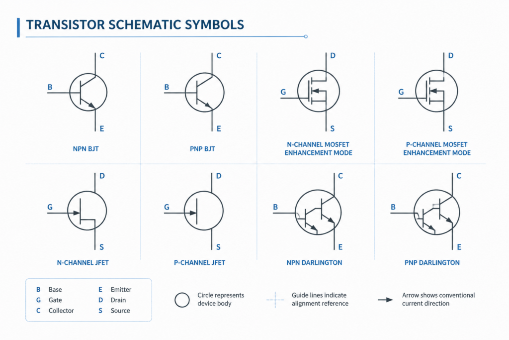
Accurate schematic symbols help electrical and electronic drawings communicate device function clearly. This resource provides a DWG collection of schematic transistor symbols for use in AutoCAD and compatible CAD software.
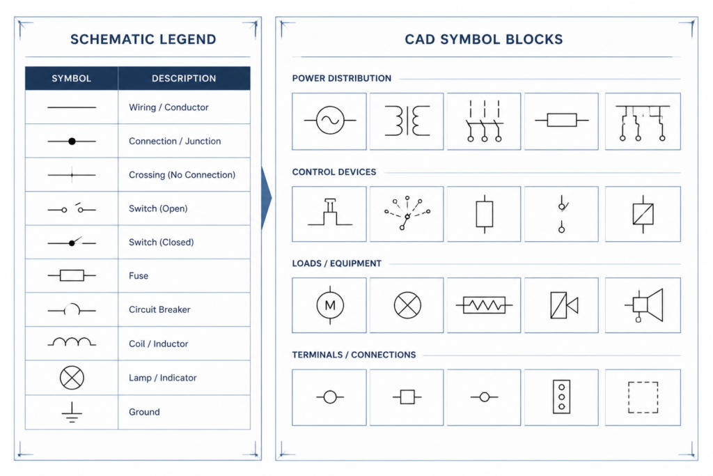
Use the supplied symbols as drafting components for circuit diagrams, equipment documentation, and related design records. Before issuing a drawing, compare symbol appearance, orientation, and naming with the project’s drafting conventions and electrical legend.
Discover a comprehensive DWG file featuring detailed **Schematic Transistors Symbols** designed specifically for electrical and electronic circuit diagrams. This CAD Block collection includes a wide variety of commonly used transistor symbols, making it an essential resource for engineers, architects, and students working on schematic designs. Perfectly compatible with AutoCAD and other leading CAD software, these symbols streamline the creation of accurate circuit schematics, PCB layouts, and technical documentation. Enhance your project efficiency and ensure standardized presentations by integrating these high-quality, ready-to-use Schematic Transistors Symbols into your next AutoCAD project.
Please log in or register to download this file.
Using schematic transistor symbols in CAD drawings
Transistor symbols convey relationships between terminals and indicate the intended device category within a circuit diagram. In a CAD file, reusable blocks can make schematic drafting more consistent and reduce the need to redraw common graphical elements.
What to check before placing a symbol
- Confirm that the selected symbol matches the device representation required by the circuit documentation.
- Review terminal orientation and connection points so wires meet the symbol cleanly.
- Keep symbol scale, line appearance, and text placement consistent with the drawing template.
- Check the project legend for naming, annotation, and graphical conventions.
- Verify the completed schematic against the applicable design documentation and engineering review process.
Related CAD documentation topics
Transistor symbols are most useful when they fit into a broader electrical drafting workflow. Related reference subjects include schematic symbols, electrical legends, panel and distribution documentation, equipment layouts, cable and conduit drafting, and single-line diagram concepts. Connecting these topics helps keep component graphics consistent across the drawing set.
DWG compatibility and editing practice
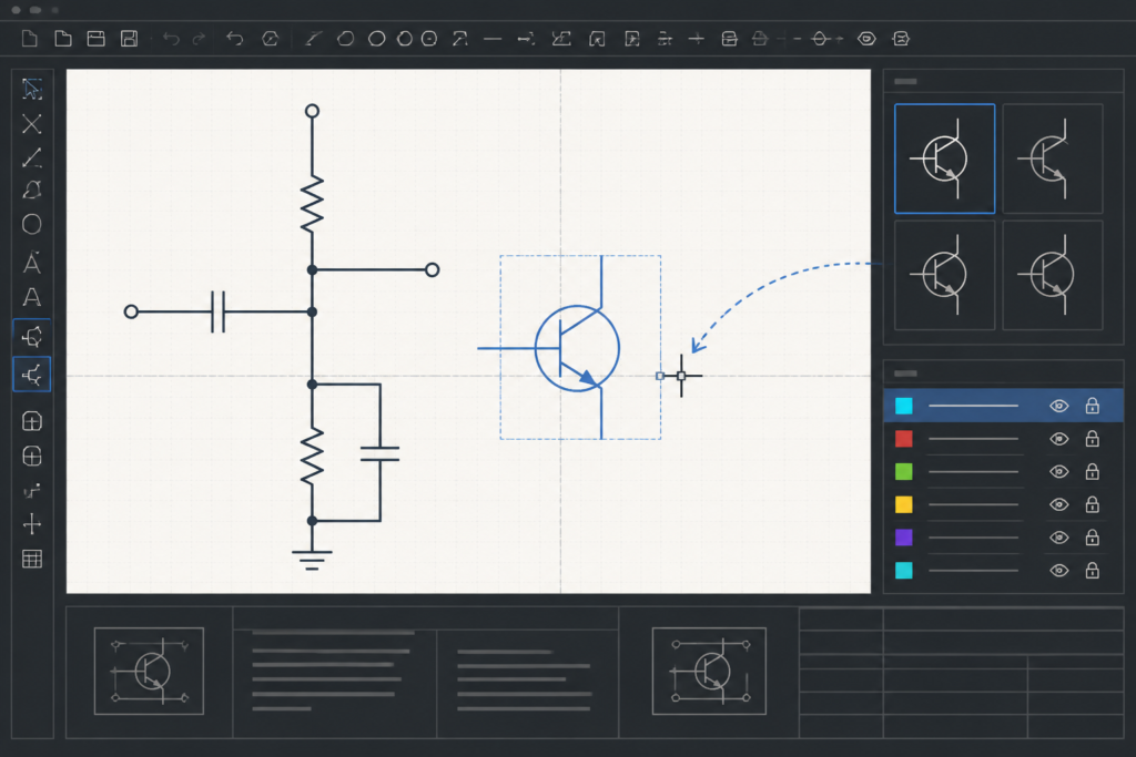
The source file is intended for AutoCAD and other leading CAD software. After opening the drawing, inspect layers, block behavior, insertion points, and annotation before incorporating a symbol into a project template. Preserve the original download as a reference copy and make project-specific edits in a separate working file.
Frequently asked questions
What is included in this transistor symbol DWG?
The source content describes a collection of commonly used schematic transistor symbols intended for electrical and electronic circuit diagrams.
Can these symbols be used in AutoCAD?
Yes. The resource is described as compatible with AutoCAD and other leading CAD software. Confirm file behavior and layer requirements in the target CAD environment before production use.
Are these symbols suitable for a PCB layout?
The source describes use in circuit schematics, PCB layouts, and technical documentation. The symbol file should still be checked against the project’s library, conventions, and engineering requirements.
How should transistor symbols be documented?
Use the project electrical legend and drafting standards to control orientation, labels, connection points, and graphical consistency. A qualified reviewer should confirm that the schematic communicates the intended circuit correctly.
Should the downloaded symbols be modified?
They may be adjusted to suit a project template, but retain an untouched reference copy and document any changes made to layers, blocks, labels, or graphical presentation.

Leave a Reply
You must be logged in to post a comment.