
Schematic symbols connectors DWG files help organize the graphical language used in electrical and electronic drawings. Instead of redrawing connector representations, a CAD block collection can provide reusable symbols for circuit diagrams, wiring layouts, PCB documentation, and related schematic work.
This page introduces the purpose of connector symbols, the role of DWG blocks in drafting workflows, and practical checks to make before placing any downloaded CAD content into a project. Use the source download as a reference resource, then verify its geometry, layer behavior, naming, and drafting conventions against the requirements of your own drawing set.
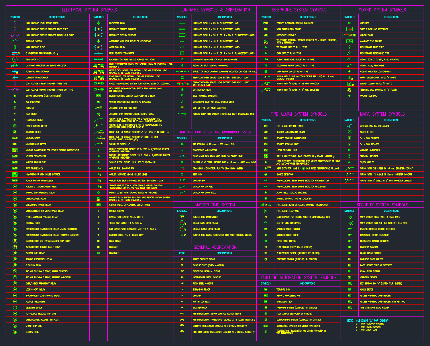
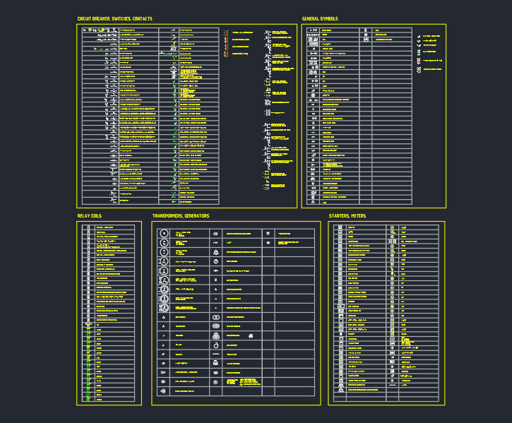
Discover a comprehensive DWG file featuring high-quality schematic symbols connectors, designed to streamline your electrical and electronic CAD projects. This CAD block collection includes a wide range of standard connector symbols, ensuring accurate and professional circuit diagrams. Ideal for engineers, architects, and designers, these schematic symbols connectors help improve workflow efficiency in creating wiring layouts, PCB designs, and system schematics. Fully compatible with AutoCAD and other leading CAD software, the file ensures seamless integration into your projects, enhancing clarity and precision in technical documentation. Perfect for both educational and professional use cases.
Please log in or register to download this file.
What connector symbols communicate
A connector symbol is a graphical shorthand for an electrical or electronic connection point. Depending on the drawing type, it may help identify an interface between conductors, a device, a cable, a circuit board, or another schematic element. The symbol itself is not a substitute for the project documentation that defines connection details, terminal identification, or equipment requirements.

Why use a DWG block collection
Reusable DWG content can reduce repetitive drafting and support a more consistent visual language across related drawings. In an AutoCAD workflow, connector symbols may be inserted, copied, positioned, and coordinated with other schematic graphics. The practical benefit comes from applying the symbols consistently—not simply from having a large library of blocks.
Checks before using CAD blocks
- Review the geometry: Confirm that the symbol is clear at the intended drawing scale and that its graphic meaning is understood by the project team.
- Inspect layers and properties: Check layer names, colors, line behavior, block properties, and any embedded attributes before combining the content with an established CAD standard.
- Check insertion behavior: Verify that the block can be placed, moved, rotated, and edited without producing unexpected results in the host drawing.
- Coordinate labels: Make sure connector labels, terminal references, wire numbers, and related annotations follow the conventions used by the rest of the schematic.
- Separate symbols from design verification: A symbol library supports documentation, but it does not confirm circuit operation, pin assignments, compatibility, or installation requirements.
Relationship to other electrical CAD resources
Connector symbols are most useful when they are considered alongside electrical symbols, wiring diagram conventions, single-line diagram concepts, panel documentation, and CAD layer organization. A consistent symbol and layer strategy makes it easier to read relationships between devices and conductors across plan fragments and schematic sheets.
For drawing-reading education, compare a connector symbol with the surrounding conductors and labels rather than interpreting it in isolation. For production drafting, coordinate the block library with the project template, title-block requirements, annotation rules, and document-control process.

Reference use of the source file
The supplied DWG resource is presented as a reusable collection of schematic connector symbols for AutoCAD and other compatible CAD workflows. Before incorporating it into a controlled drawing, review the actual file contents and confirm that the available symbols match the intended documentation task. Treat the download as drafting content and reference material, not as a verified electrical design.
Frequently asked questions
What is a schematic symbols connectors DWG file?
It is a DWG-format CAD resource containing graphical connector symbols intended for use in electrical or electronic schematic documentation. The exact geometry and organization should be reviewed in the file before project use.
Can these symbols be used in AutoCAD?
The source content describes the collection as compatible with AutoCAD and other leading CAD software. Compatibility should still be checked in the specific software version and template used for a project.

Are connector symbols the same as connector specifications?
No. A schematic symbol communicates graphical relationships in a drawing. It does not by itself define a connector’s physical construction, terminal arrangement, electrical capability, or suitability for a particular application.
What should I check after importing a DWG block?
Review the block geometry, insertion behavior, layers, line properties, attributes, text, and annotation conventions. Also check how the block interacts with the project’s existing CAD standards.
Can this file replace an electrical design review?
No. CAD symbols support drafting and communication, but design teams must independently verify circuit relationships, documentation accuracy, and project-specific engineering requirements.


Leave a Reply
You must be logged in to post a comment.