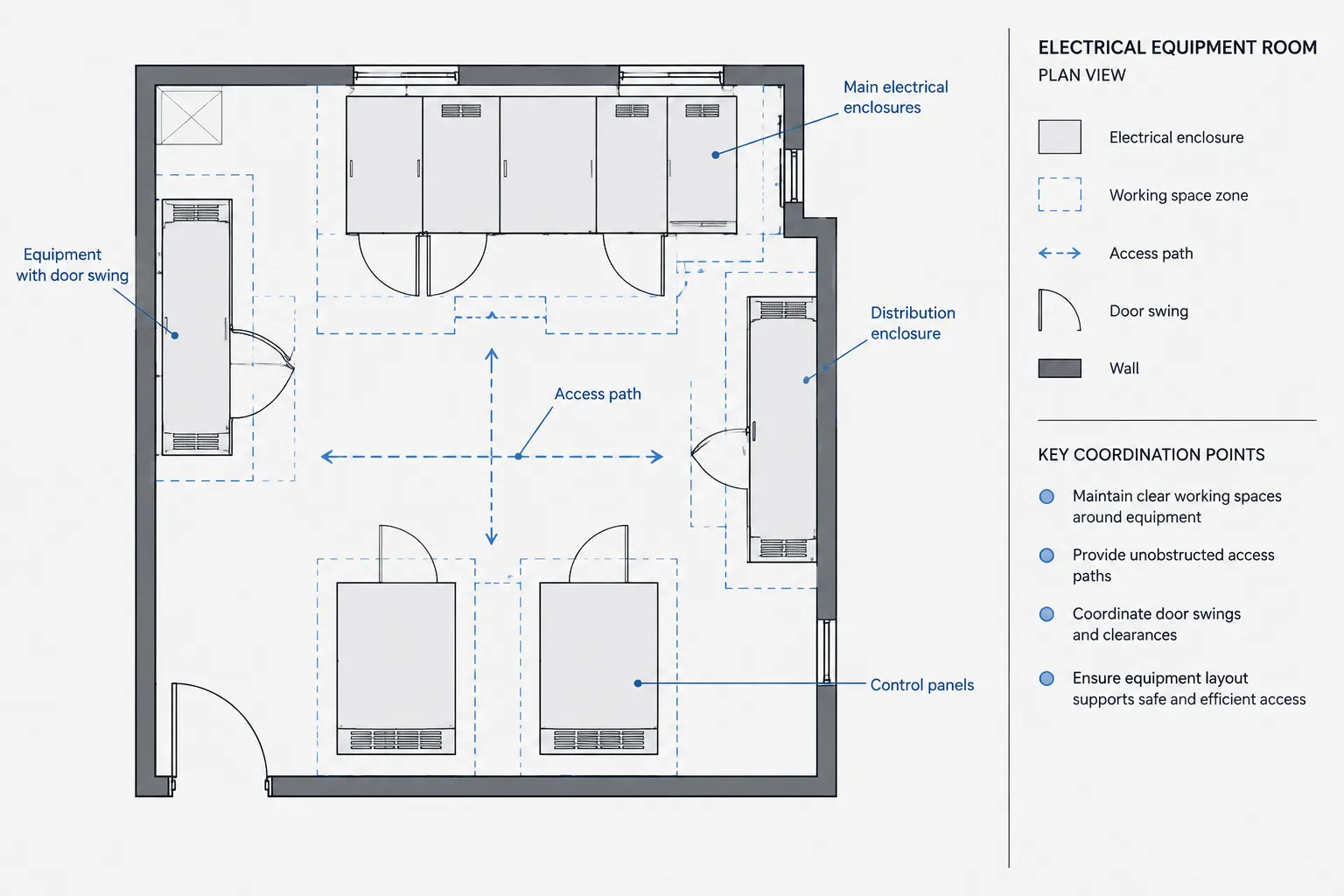
Electrical equipment clearances in CAD should communicate design intent without overstating what a generic block or boundary can verify. Effective drawings distinguish the equipment footprint from working space, service access, door movement, removal paths, and broader coordination zones.
This guide explains how to organize those graphics, coordinate them with other building systems, and keep their meaning clear through labels, layers, dimensions, enlarged views, and drawing-quality checks.
Electrical equipment layouts should communicate more than the location of each panel, switchboard, transformer, enclosure, or control cabinet. The drawings also need to show whether people can approach, operate, inspect, and maintain the equipment without conflicts from walls, doors, piping, storage, or other building systems.
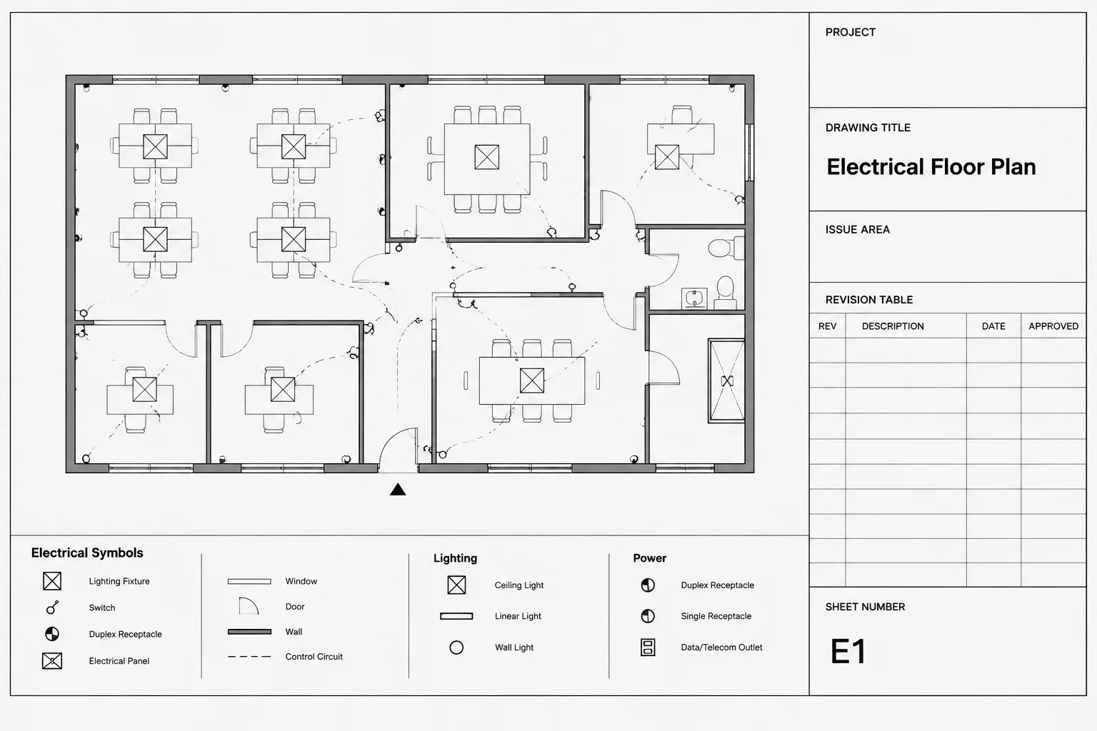
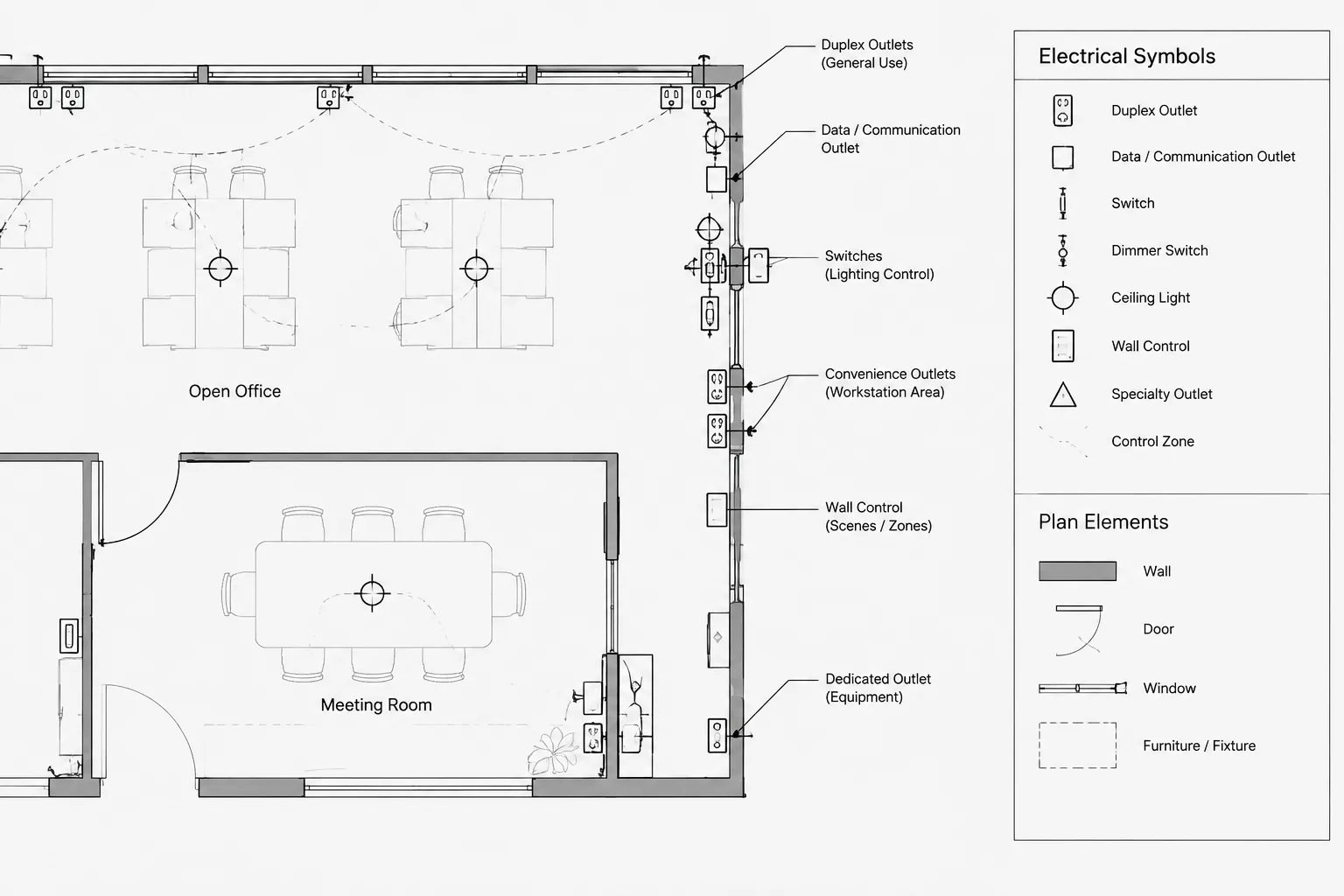
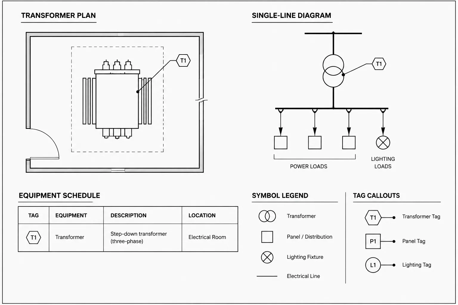
In CAD, these requirements are often represented with dashed boundaries, equipment footprints, access paths, door swings, section callouts, and coordination notes. The challenge is to make those graphics informative without implying that a generic CAD block establishes code compliance. Actual clearance requirements must be verified against the applicable codes, equipment listings, manufacturer information, project criteria, and authority requirements.
What an equipment clearance graphic represents
An electrical clearance graphic is a documentation aid placed around or in front of equipment. It may identify an area that should remain unobstructed, but its precise meaning depends on the drawing and the equipment involved.
Commonly documented areas include:
- Working space: An area associated with safe access to equipment for operation, examination, adjustment, or maintenance.
- Door and panel movement: The swing or travel required to open equipment doors, covers, or access panels.
- Manufacturer service envelope: Space identified in product documentation for component removal, ventilation, servicing, or replacement.
- Access route: A path used to reach the equipment or move major components into and out of the room.
- Dedicated or restricted zone: An area coordinated to prevent incompatible building services or construction from occupying a required zone.
- General coordination buffer: A project-defined boundary used during design coordination, even when it is not itself a regulatory clearance.
These areas should not be combined under a vague label such as “clearance” when they serve different purposes. A reviewer should be able to tell whether a dashed line represents required working space, a service recommendation, a door swing, or simply a coordination boundary.
Start with an accurate equipment footprint
A clearance zone is only useful when it is anchored to a reliable equipment footprint. Begin with the expected face, sides, rear, and access points of the equipment. Identify which side is the operating face and where doors or removable panels are located.
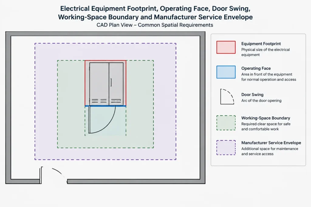
Conceptual layouts may use a representative footprint, but the drawing should not present that footprint as a verified product dimension. As equipment selections develop, compare the CAD block with current manufacturer information and update the layout. Avoid stretching a detailed block merely to make it resemble a different enclosure; this can distort door positions, connection areas, and service access.
Useful block components may include:
- The physical equipment outline
- An insertion point aligned with a wall, housekeeping base, or layout grid
- A visible indication of the equipment front
- Separate door-swing geometry
- Optional service or working-space boundaries
- Attributes for the equipment tag and description
Keeping optional graphics on distinct layers makes the same block easier to use on overall plans, enlarged plans, and coordination drawings.
Choose graphics that cannot be mistaken for construction objects
Clearance boundaries should be visually different from walls, equipment, raceways, and architectural objects. A thin dashed or phantom-style line is commonly easier to interpret than a heavy continuous line. Light screening or transparent hatching can help on enlarged plans, but dense hatching may obscure dimensions and background information.
Every boundary style should be defined in the project legend or identified directly with a note. Examples of clear labels include “working space—keep clear,” “equipment door swing,” “service access zone,” and “component removal path.” The wording should reflect verified project intent rather than making a blanket compliance statement.
Use layers to control visibility
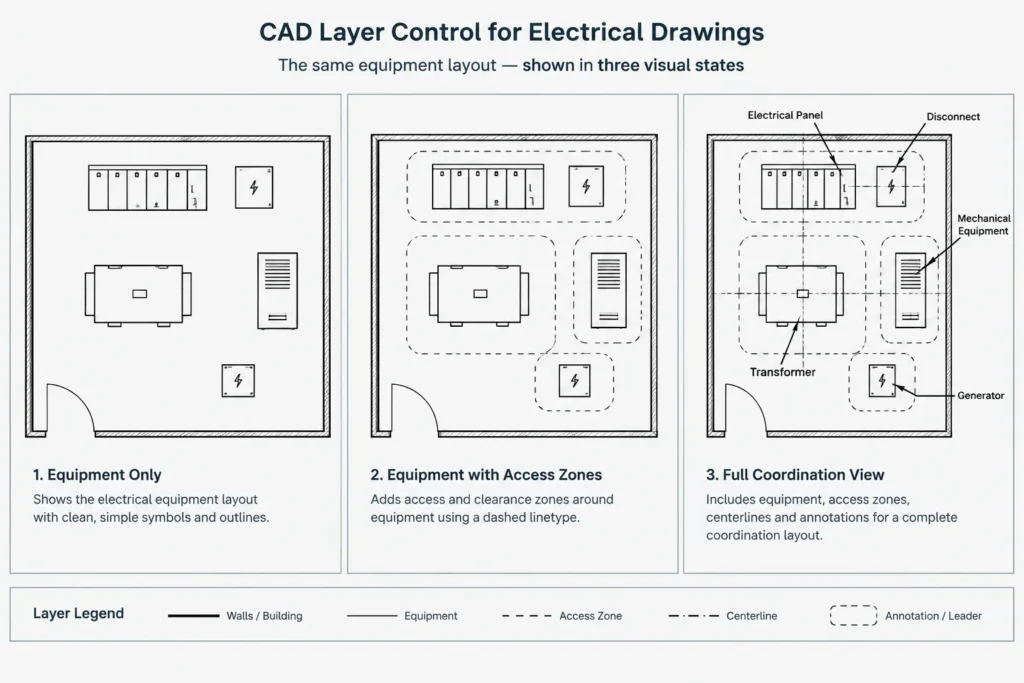
Separating equipment and clearance information by function improves plotting and coordination. A project layer structure might distinguish among equipment outlines, tags, working-space boundaries, service envelopes, door swings, dimensions, and coordination notes. The exact layer names should follow the project CAD standard.
This separation allows a drafter to display clearance graphics on a room layout while suppressing them on a less detailed overall floor plan. It also makes interference reviews easier because reviewers can isolate the relevant geometry instead of searching through a single mixed layer.
Coordinate the zones with the architectural background
Place clearance zones against the current architectural background, not an outdated snapshot. Check walls, columns, doors, casework, ceiling access, room names, and changes in floor elevation. An equipment face that appears accessible on an early plan may become obstructed after a door is reversed or a wall is shifted.
Door swings require particular attention. Show both architectural and equipment door movement where they affect access. Overlapping swing arcs do not automatically prove that the layout is unacceptable, but they clearly identify a condition requiring review.
Also consider whether the room arrangement provides a practical path to the equipment. A clear rectangle immediately in front of an enclosure does not solve a layout problem if fixed construction blocks the approach or prevents equipment replacement.
Coordinate overhead and adjacent systems
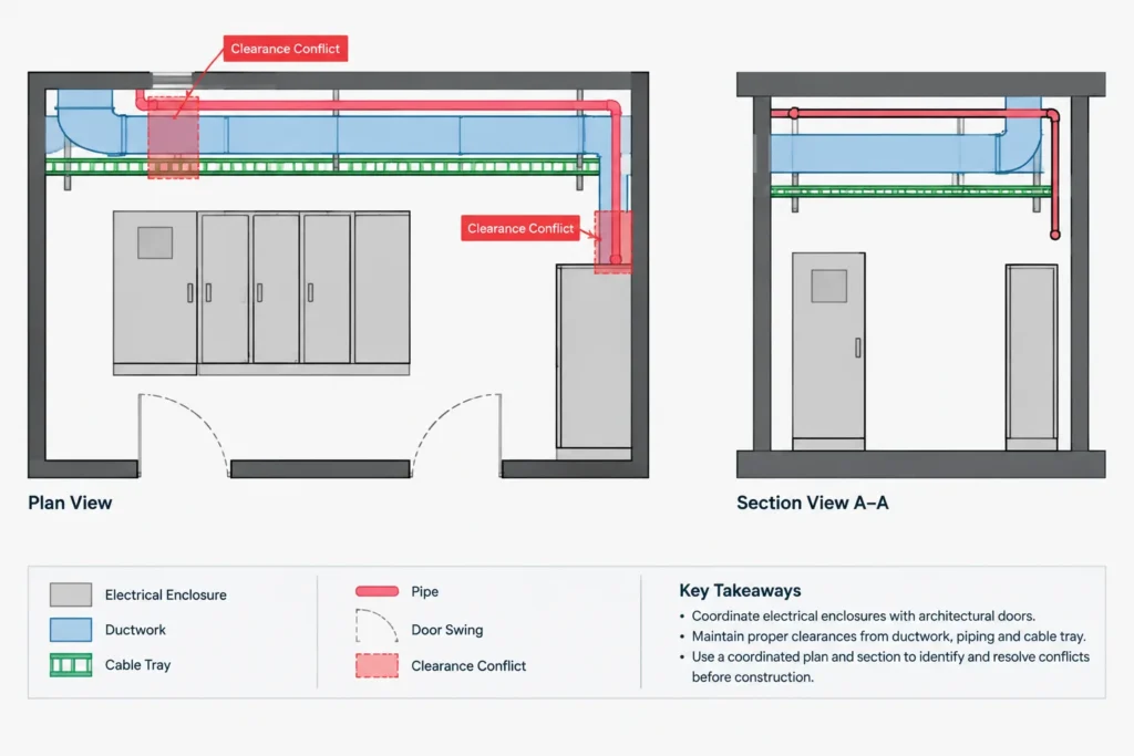
A floor plan alone cannot reveal every conflict. Compare the electrical layout with reflected ceiling plans, structural drawings, mechanical layouts, plumbing plans, fire protection drawings, and coordinated models where available.
Potential conflicts include:
- Ducts or pipes crossing a restricted zone
- Cable tray blocking equipment doors or removable sections
- Ceiling systems preventing top access
- Structural framing interfering with incoming raceways
- Housekeeping bases projecting into access routes
- Nearby equipment creating overlapping service envelopes
- Storage, shelving, or movable furnishings occupying designated working space
Do not hide a coordination problem by clipping the clearance polyline around an obstruction. Preserve the intended boundary and resolve or document the conflict. If another discipline is expected to relocate an object, use the project issue-tracking or redline process rather than relying only on a small plan note.
Use enlarged plans, sections, and elevations when needed
Overall plans may be too crowded to show access conditions clearly. An enlarged electrical room plan can display equipment faces, clear zones, door swings, dimensions, wall relationships, and identification tags at a readable scale.
Sections and elevations are useful when the concern is vertical rather than horizontal. They can document overhead coordination, stacked equipment, wall-mounted devices above floor-standing gear, ceiling access, or removal paths. Reference these views from the plan so reviewers understand that the drawings describe the same arrangement.
Keep dimensions associated with their source. Physical enclosure dimensions should be based on verified equipment information. Regulatory working-space dimensions should come from the applicable project criteria and code analysis. Manufacturer service envelopes should be identified as such rather than presented as universal code requirements.
Avoid common drafting mistakes
| Drafting problem | Why it causes confusion | Better approach |
|---|---|---|
| Using an unlabeled dashed rectangle | Reviewers cannot determine what the boundary represents. | Label the zone or define its line style in the legend. |
| Building clearance geometry into every visible block | Overall plans become cluttered and overlapping zones are difficult to read. | Use optional block components or separately controlled layers. |
| Assuming a generic block has correct dimensions | The block may not match selected equipment or current product information. | Verify and update footprints during design development. |
| Showing only open floor area | Vertical and overhead conflicts remain hidden. | Add sections, elevations, or coordination views where necessary. |
| Calling every boundary code clearance | Service zones and project buffers may have different sources. | Name each boundary according to its actual purpose. |
| Using a note that says “maintain required clearance” without graphics | The intended area may remain ambiguous during coordination. | Combine concise notes with visible, reviewable geometry. |
Quality-control checklist
Before issuing the drawing, review the clearance documentation as part of the electrical CAD quality-control process:
- Confirm that the equipment front and access sides are identifiable.
- Verify that footprints correspond to the current design information.
- Check that each boundary has a defined meaning.
- Review architectural door swings and fixed obstructions.
- Compare the plan with overhead and adjacent building systems.
- Confirm that dimensions are sourced and not inherited from an unverified block.
- Check consistency among plans, enlarged views, sections, and equipment schedules.
- Plot the sheet to ensure dashed lines, screening, and labels remain legible.
- Remove obsolete zones left behind after equipment relocation.
- Flag unresolved conflicts through the project coordination process.
Make the drawing support verification
The goal of showing electrical equipment clearances in CAD is not to decorate the plan with dashed rectangles. It is to make access assumptions visible, distinguish different types of space, and give the project team geometry that can be reviewed across disciplines.
A well-drafted layout connects verified equipment footprints, clearly labeled zones, current backgrounds, coordinated views, and traceable dimensions. That approach helps reviewers find conflicts early while avoiding the false impression that a generic block or standard-looking boundary is automatically suitable for every project.
Build a traceable clearance-documentation system
A useful clearance graphic has three connected parts: the equipment object, the access-zone geometry, and an annotation that defines the zone’s purpose. Keeping those parts associated makes it easier to review the layout when equipment moves or product information changes.
The annotation should identify whether the boundary comes from project criteria, equipment information, a coordination decision, or another verified source. Avoid notes that imply universal compliance when the drawing only shows a preliminary or project-defined envelope.
Separate design status from graphic appearance
A polished dashed boundary can look authoritative even when it is based on an early assumption. Use drawing notes, block attributes, or project review conventions to distinguish preliminary geometry from verified information. The visual style alone should not be treated as evidence that the boundary has been checked.
Keep revisions synchronized
When equipment is relocated, replaced, rotated, or resized, review every related access zone, door swing, dimension, callout, section, and elevation. Moving only the equipment outline can leave detached or obsolete clearance graphics that appear valid on the issued sheet.
Before publication, compare the plan with equipment schedules and referenced detail views. Consistent tags and view references help reviewers confirm that each drawing describes the same equipment arrangement.
Frequently asked questions
Should a clearance zone be included inside the equipment CAD block?
It can be included as an optional component, but it should remain independently controllable. Separate layers or visibility controls help prevent clutter and allow the boundary to be updated without altering the physical equipment outline.
What is the difference between working space and a service envelope?
Working space relates to access for interacting with or maintaining equipment under applicable project requirements. A service envelope may come from manufacturer information and can address ventilation, component removal, or replacement. The drawing should label each area according to its actual purpose.
Can an unlabeled dashed rectangle represent equipment clearance?
It may be intended to do so, but reviewers cannot reliably determine its meaning without a label or legend definition. The same line style might otherwise be interpreted as hidden work, demolition, overhead construction, or a general coordination boundary.
When is a plan view insufficient?
A plan view may be insufficient when access depends on overhead conditions, wall-mounted equipment, removable components, structural framing, ceiling systems, or vertical routing. A coordinated section or elevation can make those relationships reviewable.
Does showing a clear zone prove code compliance?
No. The graphic documents an intended area, but compliance depends on verified equipment information, applicable requirements, project conditions, and professional review. Generic CAD geometry should not be treated as an automatic compliance determination.
How should clearance conflicts be recorded?
Keep the intended boundary visible and identify the interfering object through the project’s coordination, markup, or issue-tracking process. Trimming the zone around the obstruction can conceal the conflict and weaken the drawing record.
Leave a Reply
You must be logged in to post a comment.