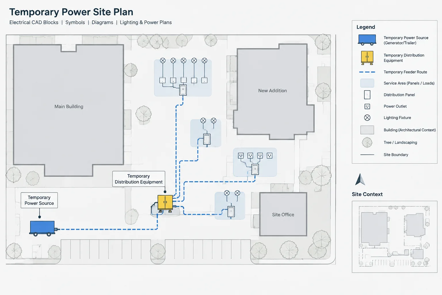
Temporary electrical power plans in CAD require more than placing equipment and connection symbols over a construction background. The drawing must explain where power originates, how it moves through the temporary distribution system, which areas or loads it serves, and how the arrangement changes during the project.
This guide focuses on the documentation workflow: defining the drawing boundary, organizing source-to-load relationships, separating work by status, coordinating plan and diagram identifiers, and preparing readable phase views. Project-specific electrical values, protection requirements, equipment selection, and installation methods must be established by qualified professionals using verified design information.
A temporary electrical power plan documents how power is intended to support construction, renovation, events, testing, or other limited-duration activities. Although the installation may be temporary, the drawing still needs a clear structure. Reviewers must be able to identify the source, follow distribution paths, distinguish temporary work from permanent systems, and understand how the arrangement changes as the project progresses.
The CAD plan should communicate design intent rather than serve as a generic collection of receptacle and panel symbols. Temporary equipment, feeders, routing constraints, construction phases, and removal responsibilities all need coordinated documentation. Actual equipment ratings, conductor information, protection requirements, and installation methods must be established and verified by qualified project professionals.
Define the purpose and drawing boundary first
Before placing symbols, establish what the temporary power drawing is expected to cover. A plan for early site operations may have a different boundary than one supporting interior renovation. Some projects need a single overall plan, while others require separate site, floor, distribution, and phase drawings.
The drawing scope may include:
- Temporary service or other approved source locations
- Temporary switchboards, panels, transformers, or distribution equipment
- Feeders and branch distribution paths
- Temporary receptacles, lighting, and dedicated connection points
- Connections to construction offices, trailers, hoists, pumps, tools, or similar loads
- Crossings, overhead routes, underground routes, and protected pathways
- Project phases, relocations, and removal limits
- Interfaces with permanent electrical work
State the limits clearly in the title, notes, or key plan. If only part of the site is shown, use match lines and references so the route does not appear to stop without explanation.
Build a source-to-load documentation structure
A useful temporary power plan can be read from source to load. Start with the power source, continue through distribution equipment, and end at the temporary loads or service areas. This hierarchy should remain recognizable even when the actual route is complex.
Identify the source
Label each source with a unique equipment identifier. The source might be a temporary service, generator, existing distribution point, or other project-defined supply. Avoid using a generic note such as “power from existing” without identifying where the reader should look for the connection information.
If source details are documented on another sheet, provide a drawing reference. The plan, single-line diagram, schedule, and notes should use the same identifier.
Show intermediate distribution
Temporary distribution equipment should be represented with consistent plan symbols and tags. Where several similar units appear, assign distinct identifiers rather than relying only on location. Equipment tags make it easier to coordinate plans with diagrams, load information, and field markups.
Use leaders carefully when the equipment footprint is too small to contain a readable tag. Keep the leader endpoint unambiguous, especially in crowded construction areas.
Define loads and service areas
Not every temporary load requires the same level of graphic detail. Repeated general-use points may be shown with symbols, while larger or specialized loads may need individual tags and schedule references. Where the plan represents a service area rather than an exact device location, use a boundary, keyed note, or labeled zone so readers do not mistake it for a precise rough-in point.
Separate temporary, existing, and permanent work
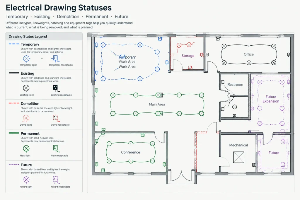
Status clarity is one of the most important parts of the drawing. Temporary systems often occupy the same plan as existing infrastructure, demolition work, and future permanent equipment. If all four use similar graphics, the plan becomes difficult to interpret.
| Status | Recommended drafting treatment | Documentation purpose |
|---|---|---|
| Temporary | Dedicated layers, symbols, tags, or linetypes | Identifies limited-duration work covered by the plan |
| Existing to remain | Screened or visually secondary graphics | Provides context and identifies available infrastructure |
| Existing to be removed | Demolition graphics coordinated with notes | Clarifies removal or disconnection scope |
| Permanent new work | Project-standard new-work graphics | Distinguishes completed construction from temporary support systems |
| Future phase | Clearly labeled phase graphics | Prevents future arrangements from being interpreted as current work |
Do not depend on color alone. Drawings may be printed in monochrome, viewed on different displays, or copied at reduced quality. Combine color with linetype, lineweight, tags, notes, or hatching.
Draft routing without implying unsupported precision
Temporary feeder and cable routes may change as access, staging, and construction conditions develop. The drawing should make clear whether a line represents an exact coordinated route, a preferred corridor, or a diagrammatic connection.
Use distinct graphics for relevant routing conditions, such as overhead, surface, concealed, or underground pathways. Add a legend that explains the graphical distinction. Where a route changes condition, mark the transition rather than allowing the same line to continue without clarification.
Important route coordination points may include:

- Roadways and pedestrian paths
- Building entrances and temporary partitions
- Material staging and equipment operation areas
- Excavation zones and planned site work
- Areas scheduled for demolition
- Vertical transitions between floors
- Connections that continue on another drawing
Avoid drawing diagonal lines through walls, rooms, or site features merely to create a short path. Even a diagrammatic route should be arranged so its intent is understandable.
Coordinate the plan with a temporary power single-line diagram
The floor or site plan explains physical location and general routing. A single-line diagram explains the distribution relationships. These views should complement each other rather than repeat conflicting information.
Check that every tagged source and major distribution unit on the plan appears on the diagram when applicable. Likewise, equipment shown on the diagram should have a plan location or a note explaining why it is not located on that drawing.
Coordinate the following fields across documents:
- Equipment identifiers
- Source and downstream relationships
- Feeder or circuit references
- Load descriptions
- Temporary and permanent status
- Phase or sequence designation
- References to schedules and details
Electrical values should come from verified design information. Do not infer ratings or conductor data from symbol names, copied details, or equipment footprints.
Use phases to show how the arrangement changes
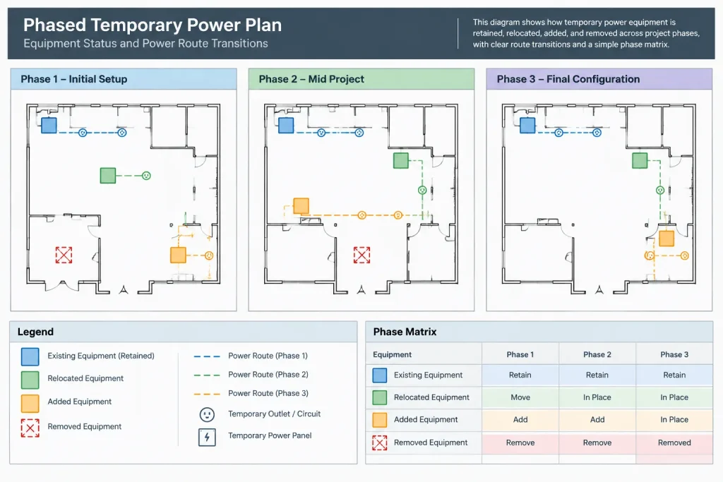
A temporary system may be relocated or expanded as construction advances. Showing every phase on one plan can create overlapping routes and contradictory notes. Consider separate phase views, controlled layer states, or clearly divided plan areas.
Each phase should answer three questions: what is installed, what remains in service, and what is removed or relocated. A phase matrix can summarize equipment status without forcing the reader to compare several dense plans visually.
Use stable equipment identifiers when the same unit is relocated, but add phase-specific location references where necessary. If an identifier is reassigned to different equipment, the drawing history can become misleading.
Create a focused legend and note set
The legend should contain only symbols and linetypes used on the temporary power drawings. Include temporary distribution equipment, receptacle or connection symbols, routing conditions, continuation markers, and status graphics. If a symbol is shared with the permanent electrical legend, confirm that it has the same meaning in both places.
General notes should define drawing conventions rather than attempt to replace project engineering. Useful note topics include:
- Whether routes are diagrammatic or coordinated locations
- How temporary work is visually identified
- Where equipment and feeder information is documented
- How connections continuing beyond the view are referenced
- Which backgrounds or project phases apply
- Who must verify conditions before final documentation or installation
Avoid broad notes that transfer unresolved drawing conflicts to the field. When a coordination issue is known, identify it specifically and track it through the project review process.
Organize CAD layers for editing and plotting
Temporary power should be separable from permanent work without duplicating the entire architectural background. A practical layer structure may distinguish equipment, devices, feeders, routing types, text, phase graphics, and removal work. Follow the project layer standard where one exists.
Keep tags and leaders associated with the system they describe. Placing all annotation on one general text layer makes it difficult to produce clean phase plots or discipline-specific views. Test layer visibility in every intended sheet view before issue.
Perform a final coordination review
Review the temporary power plan as a connected documentation package. Trace each path from source through distribution to its destination. Confirm that continuation points, vertical transitions, and references lead somewhere valid.
- Verify that symbols match the legend.
- Confirm that equipment tags are unique and consistent.
- Compare plan identifiers with the single-line diagram and schedules.
- Check that status graphics remain understandable in monochrome.
- Review routing against current architectural and site backgrounds.
- Confirm that phases do not display incompatible arrangements together.
- Remove abandoned leaders, duplicate symbols, and obsolete revision graphics.
- Plot the sheets at their intended scale and inspect crowded areas.
A well-structured temporary electrical power plan does more than show where equipment might be placed. It presents a coordinated source-to-load narrative, distinguishes changing project conditions, and gives reviewers a reliable way to compare plans, diagrams, schedules, and phases. The final design and installation requirements must still be verified for the specific project, but disciplined CAD documentation makes that verification substantially clearer.
Manage the temporary power plan as a changing record
Because temporary arrangements can change with access, demolition, staging, and construction progress, revision control is especially important. A current plan should not leave obsolete routes or superseded equipment locations visible in a way that could be mistaken for active work.
When revising the CAD file, review the complete source-to-load path rather than editing only the affected symbol. A relocated distribution unit may also require changes to route graphics, continuation references, phase notes, diagram relationships, schedules, and removal limits.
Keep review markups traceable
Use equipment identifiers and drawing references in review comments instead of relying only on descriptions such as panel near entrance. Stable identifiers help the project team connect a markup to the same object across plans, diagrams, schedules, and later revisions.
- Confirm that the current background is being used.
- Resolve duplicate or conflicting equipment tags.
- Check whether a revised route changes drawing continuations or vertical transitions.
- Remove superseded symbols, leaders, and notes from issued views.
- Verify that phase and status graphics remain clear in the plotted output.
- Record unresolved coordination items for project review rather than concealing them with vague notes.
Review both spatial and diagrammatic meaning
A plan line can communicate physical routing, a preferred corridor, or only a system relationship. The graphical convention and associated notes should make that meaning clear. Reviewers should be able to distinguish a located pathway from a diagrammatic connection without making assumptions based on line position alone.
The completed package should therefore be checked in two ways: spatially, to understand equipment locations and route constraints, and logically, to follow distribution from the identified source to the intended service areas. Agreement between those views is a key measure of drawing quality.
Frequently asked questions
What should be shown first on a temporary power CAD plan?
Begin with the drawing boundary and the identified power source. From there, organize distribution equipment, routes, connection points, and service areas so the system can be followed from source to load.
How should temporary work differ from permanent electrical work?
Use a coordinated combination of layers, linetypes, lineweights, tags, symbols, hatching, or notes. Do not rely on color alone because the drawing may be printed or reproduced without reliable color distinction.
Should temporary cable and feeder routes be drawn as exact locations?
Only when the route has been coordinated and is intended to represent a defined location. Otherwise, label the graphics as diagrammatic or identify them as preferred corridors so the drawing does not imply unsupported precision.
Why coordinate the plan with a single-line diagram?
The plan communicates location and general routing, while the single-line diagram communicates distribution relationships. Matching equipment identifiers and references allow readers to connect the physical layout with the electrical system hierarchy.
How can multiple construction phases be documented clearly?
Use separate phase views, controlled layer states, or clearly divided plan areas. Each view should make it evident which equipment is installed, remains active, is relocated, or is removed during that phase.
What should be checked before issuing the drawing?
Trace every documented path, compare equipment identifiers across related documents, test status graphics in the intended plot appearance, verify continuation references, and remove obsolete revision content. Project-specific design information must also be confirmed by the responsible professionals.


Leave a Reply
You must be logged in to post a comment.