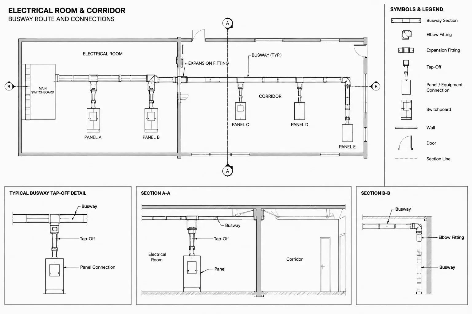
Electrical busway drafting requires more than drawing a route between pieces of distribution equipment. A useful CAD package must connect physical routing, electrical relationships, tap-off locations, equipment interfaces, and coordination references without suggesting unverified product geometry.
This guide explains how to organize electrical busway CAD drawings across plans, risers, single-line diagrams, sections, schedules, and details. It focuses on drawing clarity, cross-view consistency, revision control, and the distinction between schematic design intent and manufacturer-dependent information.
Busway can look deceptively simple on an electrical plan: a line leaves distribution equipment, follows a route, and connects to another device. In a coordinated drawing set, however, that line may represent rigid sections, directional fittings, tap-off locations, supports, transitions, clearances, and interfaces with equipment from multiple manufacturers.
Effective electrical busway CAD drawings communicate these relationships without turning the floor plan into an installation manual. The goal is to show design intent, preserve coordination information, and direct readers to the appropriate risers, schedules, elevations, and details. Final dimensions, ratings, fittings, support requirements, and connection arrangements must be verified against project criteria and approved manufacturer information.
What a Busway Drawing Package Should Communicate
Busway documentation usually extends across several drawing types. Each view answers a different question:
- Floor plan: Where does the busway travel horizontally, and what rooms or zones does it serve?
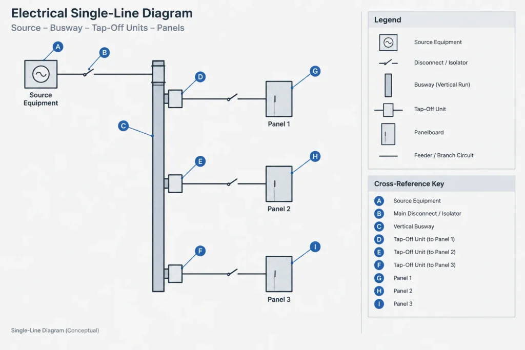
- Riser or single-line diagram: What is the electrical relationship between the source, busway, tap-off units, and downstream equipment?
- Section or elevation: At what relative height is the route located, and how does it pass other building systems?
- Equipment layout: How does the busway approach and connect to switchboards, transformers, panelboards, or other equipment?
- Schedule: Which identifier, service description, source, destination, and related drawing references belong to each run?
- Detail: What recurring transition, penetration, support concept, or equipment interface needs enlarged clarification?
No single view should carry all of this information. Good drafting distributes information intentionally while using consistent tags to connect the views.
Start with a Route That Has a Clear Identity
Assign each busway run a unique identifier before adding extensive annotation. That identifier should remain consistent on plans, risers, schedules, sections, and details. Avoid changing terminology between sheets—for example, calling the same run a “bus duct” on one sheet and “busway” on another—unless the project documentation deliberately distinguishes those terms.
A route tag can be linked to attribute data in the CAD block, but the visible annotation should remain concise. Supporting information can be placed in a schedule rather than repeated at every segment. Typical schedule fields may include:
- Busway identifier
- Source equipment
- Destination or served zone
- Service description
- Drawing and detail references
- Tap-off unit references
- Remarks or coordination status
Only include electrical characteristics that have been established by the design documents. Do not infer ratings or configuration from the apparent size of a line or from a generic CAD block.
Drafting the Busway on a Floor Plan
Use a recognizable graphic convention
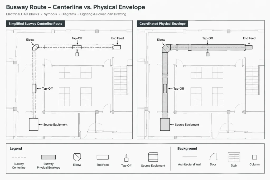
A busway route should be visually distinct from conduits, cable tray, feeders shown schematically, and architectural lines. The project legend should explain the selected line type, symbol, or double-line representation. A simplified single-line path is often clearer on an overall plan, while an enlarged room plan may show the physical envelope more explicitly.
Whatever convention is selected, use it consistently. A change from a single line to a wider outline should indicate a deliberate shift in drawing purpose or scale—not an accidental difference between drafters.
Show changes in direction intentionally
Directional changes should not be represented as vague corners. Use fitting symbols, vertices, or block-based elbows that clearly indicate where the route turns. If the system changes elevation at that point, add an elevation transition marker and reference a section or riser view.
Do not assume a drawn right-angle turn proves that a particular fitting is available. The geometry documents route intent; fitting selection must be checked against the specified busway system and manufacturer data.
Differentiate overhead and vertical portions
Plan graphics should distinguish horizontal overhead runs from vertical risers. A vertical segment can be shown with a riser symbol, directional indicator, or keyed callout linked to the appropriate riser diagram. Where the busway passes through a floor, coordinate the opening reference with structural and architectural documents without inventing an opening size.
Preserve the coordination envelope
The route centerline alone may not reveal spatial conflicts. Where coordination is important, show a separate non-plotting or controlled-plot envelope representing the space reserved for the busway and relevant access zones. Keep actual product geometry separate from clearance graphics so users do not mistake a coordination boundary for the equipment outline.
Representing Tap-Off Units and Connection Points
Tap-off units are important coordination points because they connect the busway route to downstream distribution or equipment. On a plan, each tap location should have a stable symbol and unique tag. The corresponding riser or single-line diagram should show the electrical relationship, while a schedule can carry descriptive data.
Useful plan information may include:
- Tap-off unit tag
- Associated busway run
- Downstream equipment tag
- Location reference
- Connection or detail reference
Avoid placing tap symbols approximately and relying only on schematic diagrams. Their physical locations may affect equipment access, ceiling coordination, and downstream feeder routing. At the same time, do not imply fabrication-level precision unless the drawing has been coordinated with verified product information and approved layout data.
Coordinate the Plan with the Riser or Single-Line Diagram
The floor plan and riser diagram serve different purposes but must describe the same system. The plan shows spatial routing; the riser or single-line shows electrical continuity and system hierarchy.
| Information | Floor plan | Riser or single-line |
|---|---|---|
| Physical route | Primary view | Usually simplified |
| Source and destination | Tagged or referenced | Explicitly connected |
| Tap-off locations | Spatial location | Electrical sequence |
| Elevation changes | Markers and callouts | Relative vertical relationship |
| Electrical characteristics | Limited annotation | Shown when established by design |
| Coordination conflicts | Visible against backgrounds | Not normally represented |
During quality control, compare every tagged run and tap-off unit between these views. Check that sources, destinations, identifiers, and branch relationships match. A route should not terminate at equipment on the plan while appearing to serve different equipment on the single-line diagram.
Use Sections and Elevations Where Plans Become Ambiguous
Busway routes often share congested space with ducts, piping, structural framing, cable tray, and ceilings. A floor plan may show that systems cross, but not which system passes above the other. Add a section or elevation where relative height is essential to understanding the route.
A useful coordination section can show:
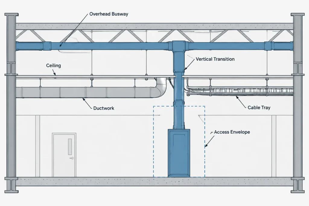
- Busway outline or centerline
- Floor, wall, ceiling, and structural references
- Nearby major building systems
- Equipment connection orientation
- Relative elevation markers
- Access or coordination envelopes where required
- References back to the plan and related details
Keep section geometry tied to the same base information used for the plan. If a route moves during coordination, update both views and review every related callout.
Organize CAD Layers and Blocks for Reliable Editing
Separate busway geometry from tags, fittings, clearance zones, and reference graphics. The exact layer names should follow the project CAD standard, but the functional separation should allow users to control plotting and coordination visibility.
A practical layer structure distinguishes:
- Busway route geometry
- Fittings and transitions
- Tap-off unit symbols
- Tags and annotations
- Coordination or access envelopes
- Existing, new, relocated, or removed work when applicable
Build reusable blocks with logical insertion points. A tap-off symbol might use the connection point as its insertion point, while an elbow block may use the route intersection. Keep attributes focused on stable information such as identifiers and references. Frequently changing notes are often better managed in schedules or external project data than embedded as extensive block attributes.
Common Busway Drafting Problems
- Unidentified route lines: A line is drawn through the building but is not linked to a source, destination, or schedule.
- Plan and riser mismatch: Tap-off units appear in different quantities or sequences across drawing types.
- Missing elevation information: The route crosses other services without a section, elevation marker, or coordination note.
- Generic blocks treated as products: A library symbol is assumed to represent actual fitting geometry or connection requirements.
- Overloaded plans: Every electrical characteristic is repeated along the route, making the spatial information difficult to read.
- Uncontrolled background changes: Architectural or structural revisions are incorporated without checking penetrations, equipment approaches, and route offsets.
- Clearance graphics mistaken for equipment: Access zones and physical outlines use the same layer or lineweight.
Quality-Control Checklist Before Issue
- Confirm that every busway run has a unique and consistent identifier.
- Compare source and destination tags across plans, risers, single-lines, and schedules.
- Check tap-off symbols against downstream equipment references.
- Review all turns, offsets, elevation changes, and vertical transitions.
- Verify that congested crossings have adequate drawing clarification.
- Confirm that equipment approaches agree with the latest equipment layouts.
- Review wall and floor crossings against current architectural and structural backgrounds.
- Separate physical geometry from access and coordination envelopes.
- Remove obsolete route segments, duplicate symbols, and abandoned callouts.
- Verify product-dependent geometry and connection details against approved project information.
Make the Drawing Set Navigable
The strongest busway documentation is not necessarily the drawing with the most information. It is the set in which users can move easily from a route on the plan to its electrical relationship on the single-line, its physical position in a section, and its descriptive data in a schedule.
Consistent identifiers, controlled CAD layers, purposeful blocks, and coordinated cross-references make that navigation possible. Treat generic CAD symbols as communication tools rather than verified products, and preserve a clear boundary between design intent and manufacturer-dependent detail. This approach produces electrical busway CAD drawings that are easier to review, revise, and coordinate throughout the project.
A Cross-View Revision Workflow for Busway Drawings
Busway revisions should be treated as coordinated drawing-set changes rather than isolated edits. Moving a route on a floor plan may affect a riser reference, tap-off location, equipment approach, section marker, penetration note, or schedule entry. The drafter should identify those dependencies before closing the revision.
Review the route by identifier
Use the busway identifier as the main search key across the drawing set. Review every occurrence of that identifier and confirm that the source, destination, route status, tap-off relationships, and detail references still agree. This is more reliable than checking sheets only by visual proximity.
Separate spatial and electrical changes
A spatial revision changes where the busway is shown, while an electrical revision changes what it serves or how it relates to the distribution system. Some revisions affect both. Classifying the change helps determine whether plans, risers, schedules, sections, or equipment layouts require updates.
Record unresolved coordination
If product geometry, connection orientation, access space, or fitting selection has not been verified, show the design intent without presenting the uncertain information as final. Use the project documentation process to identify unresolved coordination items and keep generic CAD graphics distinguishable from approved manufacturer information.
Choosing the Right Level of CAD Detail
The appropriate representation depends on the purpose of the view. An overall plan benefits from a clean route and readable tags, while an enlarged equipment area may require connection orientation, transition references, and coordination envelopes. A section should clarify vertical relationships rather than repeat every plan annotation.
- Use schematic graphics to communicate electrical hierarchy and continuity.
- Use plan geometry to communicate location, direction, and interfaces with rooms or equipment.
- Use sections and elevations to resolve vertical ambiguity and congested crossings.
- Use schedules to centralize stable descriptive information and drawing references.
- Use details to explain recurring interfaces without overcrowding the main plan.
Before issue, review the drawing at its intended plotting scale. Tags, line types, fitting symbols, and cross-references that appear clear in the CAD workspace may become difficult to distinguish on a plotted sheet.
Frequently Asked Questions About Busway CAD Drafting
Should busway be shown as a single line or an outlined object?
The representation should match the purpose and scale of the view. A single-line route can keep an overall plan readable, while an outline may better communicate the physical envelope in an enlarged coordination area. The legend should explain the convention, and changes in representation should be intentional.
What is the difference between a busway plan and a busway riser?
The plan communicates the physical route through the building. The riser communicates electrical continuity, hierarchy, vertical relationships, and connections between the source, busway, tap-off units, and downstream equipment. The identifiers and equipment relationships should agree in both views.
Can a generic busway CAD block represent an actual fitting?
A generic block can communicate design intent, fitting type, or route direction, but it should not be treated as verified product geometry. Actual fitting availability, connection arrangements, and physical requirements must be checked against approved project and manufacturer information.
Where should tap-off information be documented?
The plan should show the coordinated location and tag, while the riser or single-line should show the electrical relationship. Descriptive information and drawing references can be maintained in a schedule to avoid overloading the plan.
How should busway clearance or access areas be drawn?
Clearance and access graphics should be separated from the physical busway geometry through controlled layers, linework, or hatching. This prevents reviewers from confusing a coordination envelope with the equipment outline. Required spaces should come from verified project criteria and approved product information.
What should be checked after a busway route changes?
Review the corresponding riser, single-line diagram, tap-off references, sections, equipment approaches, schedules, penetrations, and coordination callouts. Also remove obsolete geometry and confirm that the revised route uses the same identifier throughout the drawing set.






Leave a Reply
You must be logged in to post a comment.