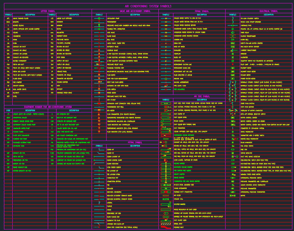
Air conditioning system symbols DWG files help CAD users communicate HVAC equipment, air distribution, and system relationships within coordinated drawing sets. A well-organized symbol library can make mechanical plans easier to read, revise, and review across architectural and engineering workflows.
Use the downloadable DWG collection as a drafting reference for air conditioning layouts, ventilation plans, and system schematics. Before issuing a drawing, confirm that each symbol matches the project legend, applicable office standards, and the requirements of the responsible design professional.
Download a comprehensive DWG file featuring essential Air Conditioning System Symbols, perfect for HVAC engineers, architects, and CAD designers. This CAD Block collection provides clearly detailed, industry-standard air conditioning symbols, ensuring accurate and professional mechanical drawings. These symbols are designed for seamless integration into your AutoCAD projects, supporting efficient drafting of air conditioning layouts, ventilation plans, and system schematics. Compatible with AutoCAD and other popular CAD software, this DWG file streamlines your workflow and enhances the clarity of HVAC design documentation. Ideal for residential, commercial, and industrial applications.
Please log in or register to download this file.
How air conditioning symbols support CAD documentation
Air conditioning symbols provide a consistent graphic language for showing equipment and system components without filling the drawing with lengthy descriptions. They help readers distinguish between physical equipment, air movement, controls, and connected services when reviewing a plan or schematic.
Symbols are most useful when they are coordinated with tags, notes, schedules, and a project-specific legend. The graphic alone may not communicate capacity, connection details, sequence of operation, or installation requirements. Those items belong in the appropriate design documents and must be verified by the project team.
What to review in an HVAC symbol library
- Equipment representation: Check how air conditioning equipment is shown in plan, elevation, and schematic views.
- Air distribution: Review the conventions used for ducts, outlets, returns, grilles, and other air-path elements when they appear in the drawing set.
- Controls and connections: Confirm that control points, piping relationships, and electrical interfaces are identified consistently with the project documentation.
- Annotation: Match symbol tags, abbreviations, linework, and notes to the drawing legend before copying content into a live project.
- Layer and block behavior: Check insertion points, block attributes, layer assignments, scaling behavior, and visibility settings after importing the DWG.
Practical AutoCAD workflow
Start by opening the DWG in a controlled project file or reference drawing. Inspect the symbols before placing them in production sheets, then remove unused content and align the remaining blocks with the project’s layer, text, and annotation conventions.
Use the library to improve drafting consistency, not to replace mechanical design decisions. Coordinate HVAC symbols with architectural backgrounds, reflected ceiling plans, equipment schedules, electrical documentation, and structural constraints. Any installation, service, or field work involving electrical or mechanical equipment should be handled by qualified professionals using approved project procedures.
Reference checklist for drawing coordination
- Confirm the symbol meaning against the project legend.
- Use consistent tags between plans, schematics, schedules, and details.
- Check that block orientation and visibility are correct in each view.
- Coordinate equipment locations with access, clearances, structure, and other building systems.
- Review plotted output so lineweights and annotations remain legible.
Frequently asked questions
What is included in an air conditioning system symbols DWG file?
The source download is described as a comprehensive collection of air conditioning symbols for HVAC layouts, ventilation plans, and system schematics. Review the actual DWG contents and project legend to confirm which symbols are available.
Can the DWG be used in AutoCAD?
Yes. The source content identifies the file for AutoCAD use and notes compatibility with other popular CAD software. Always verify import behavior, block settings, layers, and version compatibility in your working environment.
Are these symbols a substitute for an HVAC design?
No. Symbols are drafting elements that communicate design information. They do not establish equipment selection, system performance, installation requirements, or code compliance. Those decisions require project-specific engineering and review.
How should the symbols be added to a drawing set?
Inspect the blocks first, then place them using the project’s layer, annotation, tagging, and legend conventions. Coordinate the result with architectural, structural, electrical, and mechanical documentation before issue.
Why is a drawing legend important?
A legend defines how symbols, abbreviations, line types, and tags are interpreted on a particular project. It reduces ambiguity when a symbol library is adapted to different office or project standards.












Leave a Reply
You must be logged in to post a comment.