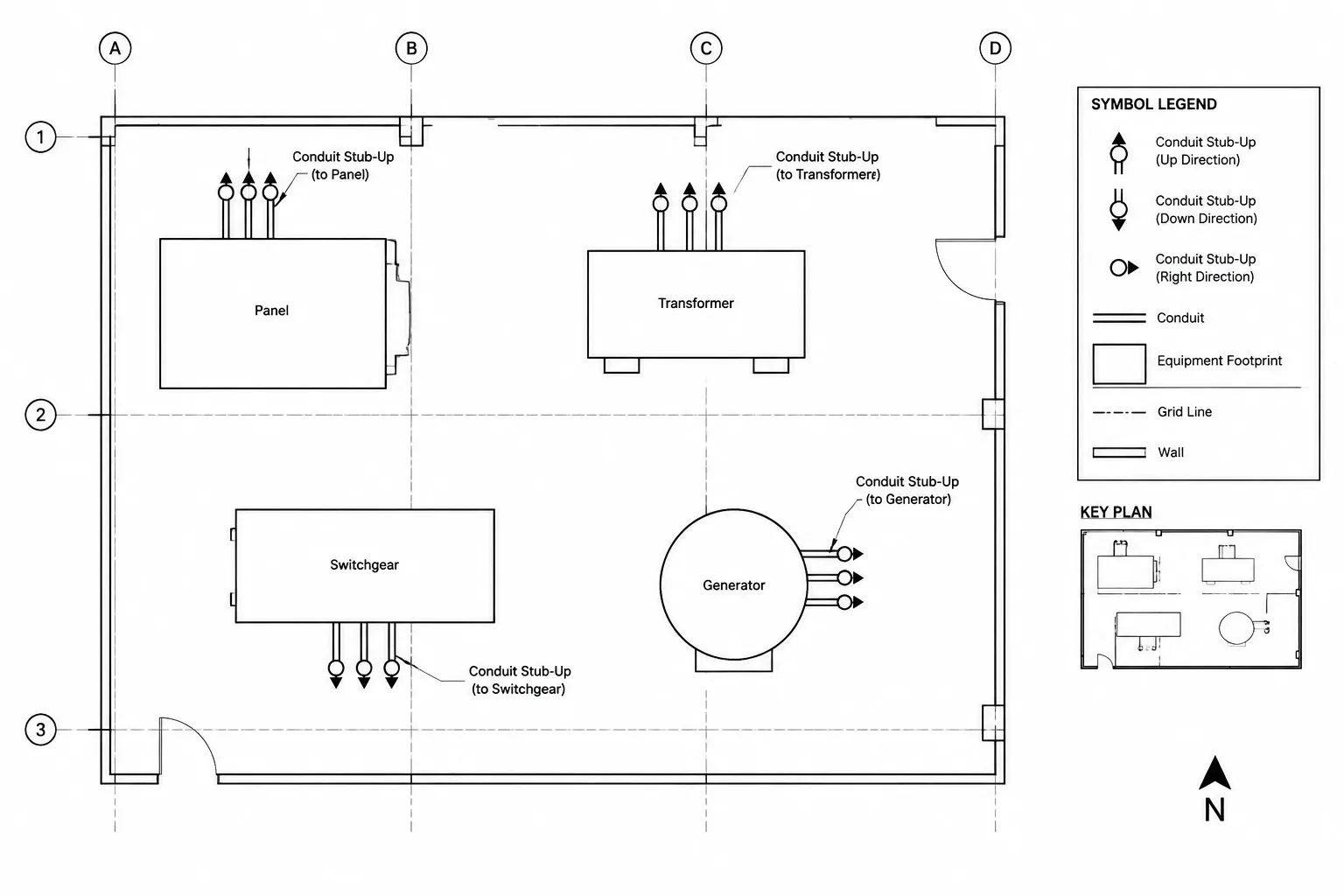
Drafting conduit stub-ups and stub-outs requires more than placing an endpoint symbol. The CAD documentation must distinguish the endpoint condition, establish its location, communicate vertical intent, and connect the raceway to related equipment or drawing references.
This guide explains how to represent these conditions consistently across electrical plans, details, schedules, and diagrams. It focuses on drawing communication and coordination rather than field installation. Project-specific conventions, approved equipment information, and the drawing legend should govern the final documentation.
Conduit stub-ups and stub-outs often occupy very little space on an electrical plan, but they can carry a surprising amount of design intent. A small symbol may need to communicate the raceway location, direction, destination, service, elevation, status, and relationship to equipment that has not yet been installed.
Clear conduit stub-up drawings do more than mark endpoints. They help coordinate electrical plans with equipment layouts, architectural backgrounds, structural elements, slab work, wall construction, and other building systems. The objective is not to reproduce installation instructions. It is to create a coordinated drawing record that tells the project team what the raceway endpoint represents and where related information can be found.
Stub-Up, Stub-Out, Sleeve, and Continuation: Know the Difference
These terms are sometimes used loosely in markups, so the drafting team should establish what each one means within the project documentation.
- Stub-up: A raceway endpoint represented as rising from a floor, slab, grade, or lower level into the depicted space.
- Stub-out: A raceway endpoint extending from a wall, floor, equipment zone, or concealed space for a later connection or continuation.
- Sleeve: A reserved penetration or pathway through construction. A sleeve is not automatically an electrical raceway and should not be shown as one unless that is the documented intent.
- Continuation: A raceway that proceeds beyond the limits of the current view, often to another plan, level, detail, or diagram.
- Spare or future pathway: A raceway reserved for later use. Its status should be stated rather than inferred from an unconnected line.
A symbol library should not treat these conditions as interchangeable. If the same graphic is used for several meanings, a tag, note, or line-type convention must resolve the difference.
What a Conduit Endpoint Symbol Needs to Communicate
The symbol itself rarely needs to contain every piece of information. A better approach is to combine a simple, readable plan symbol with a tag that connects it to notes, schedules, details, or other views.
| Information | Typical drawing method | Coordination purpose |
|---|---|---|
| Endpoint type | Distinct symbol, abbreviation, or keyed note | Distinguishes a stub-up, stub-out, sleeve, or continuation |
| Location | Plan geometry, dimensions, coordinates, or relation to fixed construction | Prevents placement from depending on visual scaling |
| Direction | Arrow, orientation marker, or section reference | Clarifies whether the raceway rises, drops, or extends horizontally |
| Service | System tag, circuit reference, feeder reference, or description | Separates power, controls, communications, and other systems |
| Destination | Equipment tag, panel reference, room reference, or continuation callout | Links the endpoint to its intended connection |
| Elevation | Elevation note, datum reference, or coordinated detail | Defines vertical intent when the plan view alone is insufficient |
| Status | Existing, new, spare, future, or demolition notation | Supports phased and renovation documentation |
Choose a Consistent Graphic Convention
There is no single plan symbol that will be understood correctly on every project. Symbol appearance can vary among firms, disciplines, clients, and drawing types. The project legend therefore matters more than relying on a supposedly universal shape.

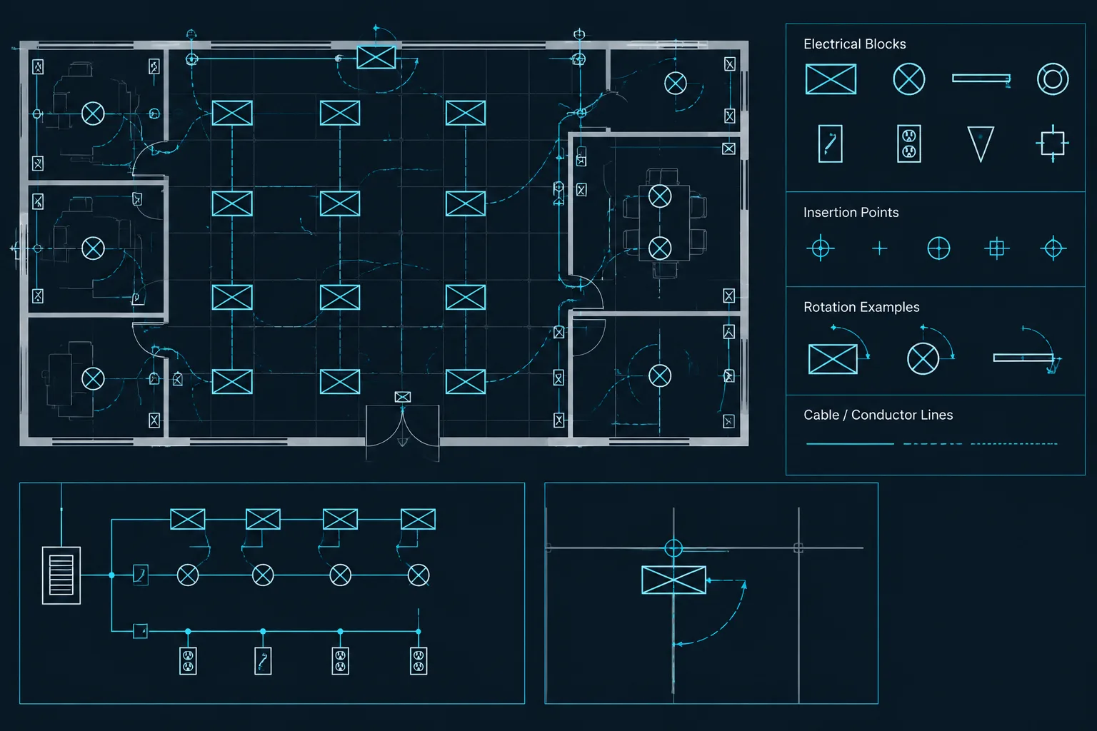
A practical convention may use a small endpoint marker, an attached direction indicator, and a nearby identifier. Keep the block compact enough for equipment areas, but avoid symbols so small that they disappear when plotted. The marker should also remain recognizable when conduit lines, equipment outlines, hatch patterns, and architectural backgrounds overlap.
If upward and downward directions use related symbols, make their difference visible without depending only on color. Printed sets, grayscale PDFs, and field copies may not preserve layer colors. Shape, line pattern, text, or an explicit abbreviation can provide a more durable distinction.
Place the Endpoint from a Reliable Reference
A stub symbol placed approximately beside an equipment block may look acceptable in CAD while remaining impossible to locate from the issued drawing. Anchor critical endpoints to stable references such as structural grids, finished faces, room geometry, or coordinated equipment connection points.
Do not assume that an equipment CAD block contains a verified connection location. Manufacturer blocks may represent only the overall footprint, and generic library blocks may not correspond to the selected equipment. When connection information is not confirmed, show the endpoint as diagrammatic and identify the need for coordination rather than presenting an unverified location as final.
Where several endpoints are grouped together, an enlarged plan or equipment connection detail can be clearer than stacking leaders and notes on the main floor plan. The main plan can show the group location and refer users to the enlarged view.
Document Vertical Intent
Plan views are effective for horizontal relationships but weak at describing vertical movement. A stub-up may start below the view plane, terminate above a floor, enter an equipment enclosure, or continue into a wall. If that vertical intent affects coordination, support the plan with an elevation, section, riser, or detail.

Elevation references should use a clearly identified project datum. Avoid isolated elevation values whose reference point is uncertain. Also distinguish between an endpoint elevation, a raceway centerline elevation, and an elevation associated with equipment or construction. These are not automatically the same.
When the final endpoint depends on selected equipment, the drawing can identify the controlling source, such as a coordinated equipment submittal or connection schedule. This preserves design intent without fabricating a fixed location.
Use Tags and Attributes for Repeated Conditions
Projects with many stub-ups benefit from identifier-based documentation. A block attribute can hold an endpoint ID, system designation, destination, status, and related detail reference. The visible tag stays short while the underlying data can support checking or schedule generation.
Useful attribute fields may include:
- Unique endpoint identifier
- Origin and destination
- Associated equipment or panel tag
- System or service description
- Raceway reference
- Elevation or datum note
- Drawing status
- Related detail, section, or schedule
- Coordination remarks
Attributes should not become a hidden substitute for visible documentation. Information essential to interpreting the printed plan must remain visible or be accessible through a clearly referenced schedule.
Coordinate Plans, One-Lines, and Schedules
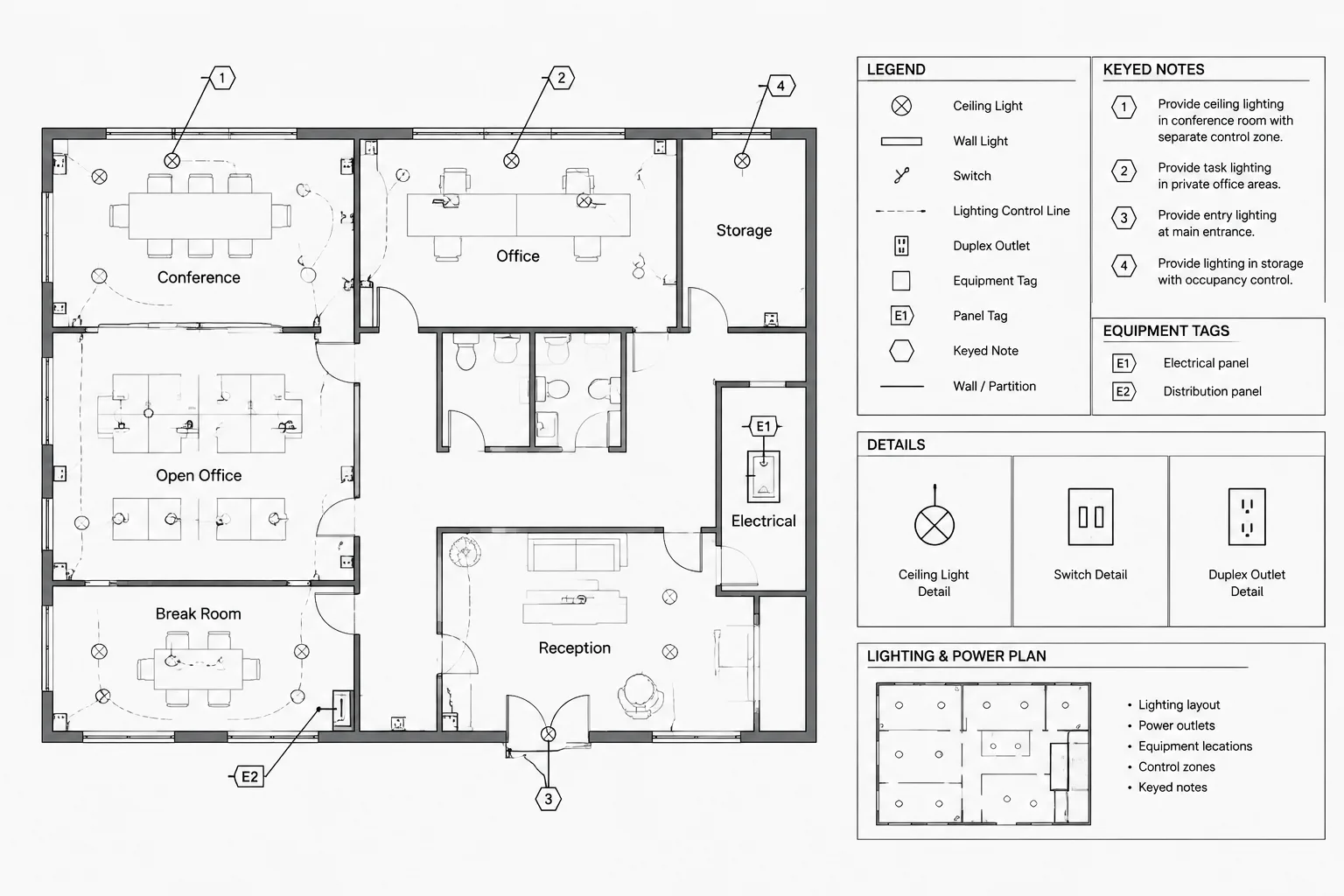
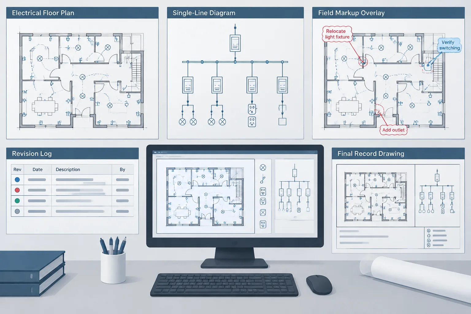
A plan answers where the endpoint is located. A single-line diagram may explain its electrical relationship. A raceway or feeder schedule may identify the pathway, while a detail or section explains the physical coordination concept. These views should share consistent tags.

Not every small branch raceway belongs on a one-line diagram, and not every diagrammatic connection needs a plan-view route. The drafting team should decide which document controls each type of information. Duplicating the same data across many sheets increases the chance of conflicting revisions.
A useful rule is to give each item one primary identifier and reuse that identifier wherever the item appears. If a stub-up is associated with a feeder, equipment connection, or reserved pathway, the corresponding references should lead reviewers to the same documented intent.
Layer and Display Strategy
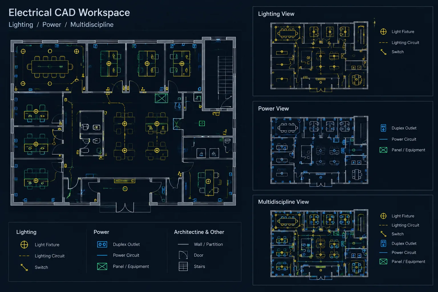
Stub symbols, route lines, tags, and coordination notes may need separate layers even when they belong to the same system. Separating them allows sheet-specific visibility and makes crowded plans easier to manage.
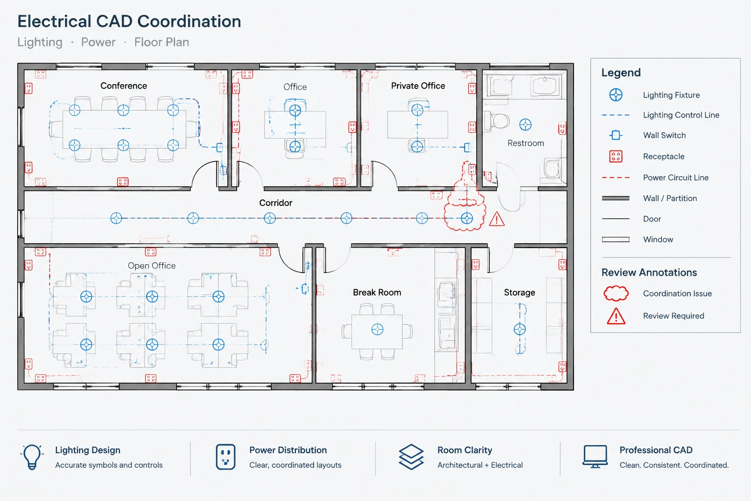
For renovation work, status may also affect layer organization. Existing pathways, new work, future provisions, and removals should remain visually distinguishable in both the CAD file and plotted output. Avoid using layer names or colors as the only explanation; the legend and notes should communicate the same status to readers who do not have the source file.
Common Drafting Problems
- Unlabeled endpoint: A conduit line simply stops, leaving users unable to tell whether it is incomplete, capped, concealed, or continued elsewhere.
- Ambiguous direction: The symbol does not clearly indicate whether the pathway rises, drops, or exits horizontally.
- Missing destination: A tag identifies a stub but does not connect it to equipment, a panel, another sheet, or a schedule.
- False precision: A generic equipment block is used to imply an exact connection point that has not been verified.
- Symbol inconsistency: Similar conditions use different graphics, or different conditions use the same graphic without qualification.
- Plan-only documentation: A complicated vertical condition is shown without a supporting section or elevation.
- Broken revision coordination: The plan tag changes while the schedule, detail, or diagram retains the previous identifier.
Recommended CAD Workflow
- Define the endpoint condition. Determine whether it is a stub-up, stub-out, sleeve, continuation, or reserved pathway.
- Select the project symbol. Use the approved project legend or establish a clear convention before placing large quantities.
- Locate it from coordinated references. Use dependable background geometry and identify uncertain connection locations.
- Assign an identifier. Connect the endpoint to the relevant equipment, system, route, or schedule.
- Add vertical information. Include an elevation, direction marker, or reference to a supporting view where needed.
- Check related drawings. Compare the plan against diagrams, equipment layouts, schedules, and referenced details.
- Test the plotted result. Confirm that symbols, leaders, and status distinctions remain readable without relying on CAD colors.
- Run a revision check. Search for duplicate, missing, or obsolete identifiers before issue.
Final Quality-Control Questions
Before issuing conduit stub-up drawings, confirm that each endpoint has a clear purpose, direction, location basis, and destination reference. Check that symbols match the legend, critical locations do not rely on scaling, and unverified equipment connections are identified as coordination items. Finally, review every referenced schedule, section, and diagram to make sure the same identifier describes the same condition throughout the drawing set.
A well-drafted stub-up is not merely the end of a line. It is a coordinated interface between plan location, vertical routing, equipment requirements, and the wider electrical documentation package.
Use the Endpoint as a Documentation Interface
A conduit endpoint often marks where information passes between disciplines or drawing types. Its plan location may depend on architectural construction, its vertical position may require a section, and its purpose may be defined by an equipment schedule or electrical diagram. Treating the endpoint as a coordinated interface helps prevent it from becoming an isolated symbol with no traceable meaning.
When reviewing the drawing, follow the endpoint in both directions. One direction should lead to a reliable location or origin. The other should lead to a destination, continuation reference, equipment tag, or clearly stated future condition. If either path is missing, the documentation may be incomplete even when the CAD geometry appears finished.
Separate Confirmed Information from Coordination Assumptions
CAD drawings should make a visible distinction between verified design information and unresolved coordination. A precise-looking symbol can imply that an equipment connection, wall position, or vertical termination has been confirmed when it has not. Where the controlling information remains pending, use an appropriate coordination note or reference instead of presenting an assumed location as final.
This distinction is especially important when backgrounds or equipment blocks change. Associative labels, disciplined layer use, and consistent identifiers can make revisions easier to find, but they do not replace a comparison against the current architectural, structural, and equipment information.
Review the Drawing as a Published Document
Final checking should include the plotted sheet or exported document, not only the working CAD file. Confirm that endpoint markers remain visible against backgrounds, leaders point to the intended objects, abbreviations are defined, and status differences remain understandable without layer color.
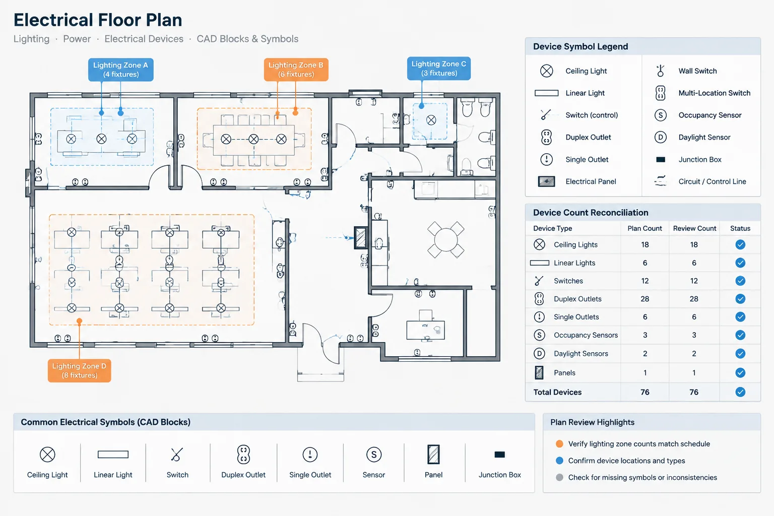
Also review referenced views as a connected set. A plan, schedule, detail, and diagram should not assign different meanings to the same identifier. When information must appear in more than one location, identify which document controls it and use the remaining views to reference that source consistently.
Frequently Asked Questions
What is the drafting difference between a conduit stub-up and a stub-out?
A stub-up generally represents a raceway rising into the depicted space from below. A stub-out represents an endpoint extending from construction, an equipment area, or a concealed space for connection or continuation. Because project terminology varies, the legend should define the intended meaning.
Should a stub-up symbol show the complete conduit route?
Not necessarily. The symbol may identify only the endpoint when the route is diagrammatic, concealed, or documented elsewhere. It should still provide a clear tag or reference that explains the raceway’s purpose and destination.
How should vertical information be shown on a plan?
Use a direction marker, elevation notation, datum reference, or callout to an elevation, section, riser, or detail. The selected method should clarify vertical intent without forcing the reader to infer it from the plan symbol alone.
Can a sleeve use the same CAD symbol as a conduit stub?
Only when a tag, note, or legend clearly distinguishes the conditions. A sleeve represents a reserved penetration or pathway and should not automatically be documented as an electrical raceway.
What information belongs in a conduit endpoint block attribute?
Useful fields can identify the endpoint, system, destination, status, related equipment, drawing reference, and coordination remarks. Information needed to interpret the printed sheet should remain visible or be available through a clearly referenced schedule.
How should an unverified equipment connection point be documented?
Show the condition as diagrammatic or subject to coordination and identify the controlling equipment information. Avoid positioning the endpoint as though its exact connection location has already been confirmed.
Why should symbol differences not rely only on color?
Layer colors may not remain distinguishable in grayscale output, printed sets, or exported documents. Shape, line pattern, text, and defined abbreviations provide more durable ways to communicate direction and status.
Leave a Reply
You must be logged in to post a comment.