
A grounding and bonding diagram explains electrical relationships that may be difficult to communicate on floor plans alone. It can show how service equipment, distribution equipment, grounding electrodes, equipment grounding paths, structural metal, separately derived systems, and other project elements relate to one another.
The diagram is not a substitute for engineering decisions, project specifications, installation details, or applicable requirements. Its purpose is to make the documented design easier to interpret and coordinate. Every connection, conductor description, and system boundary must be verified for the specific project before the drawing is issued.
Grounding and bonding are related but not interchangeable
Drawing clarity begins with terminology. Grounding generally describes an intentional connection between an electrical system and earth. Bonding describes connections that establish electrical continuity between conductive parts. An equipment grounding path provides a fault-current path through conductors, raceways, enclosures, or an approved combination of components.
A diagram should not treat these ideas as one generic network of ground lines. If every connection uses the same symbol, line, and note, the reader may be unable to determine whether the drawing represents a grounding electrode conductor, an equipment grounding conductor, a bonding jumper, or a general reference to a grounded component.
Choose the right drawing format
Grounding information can appear in several drawing types. Select the format according to the relationship that needs to be communicated.
| Drawing format | Best use | Common limitation |
|---|---|---|
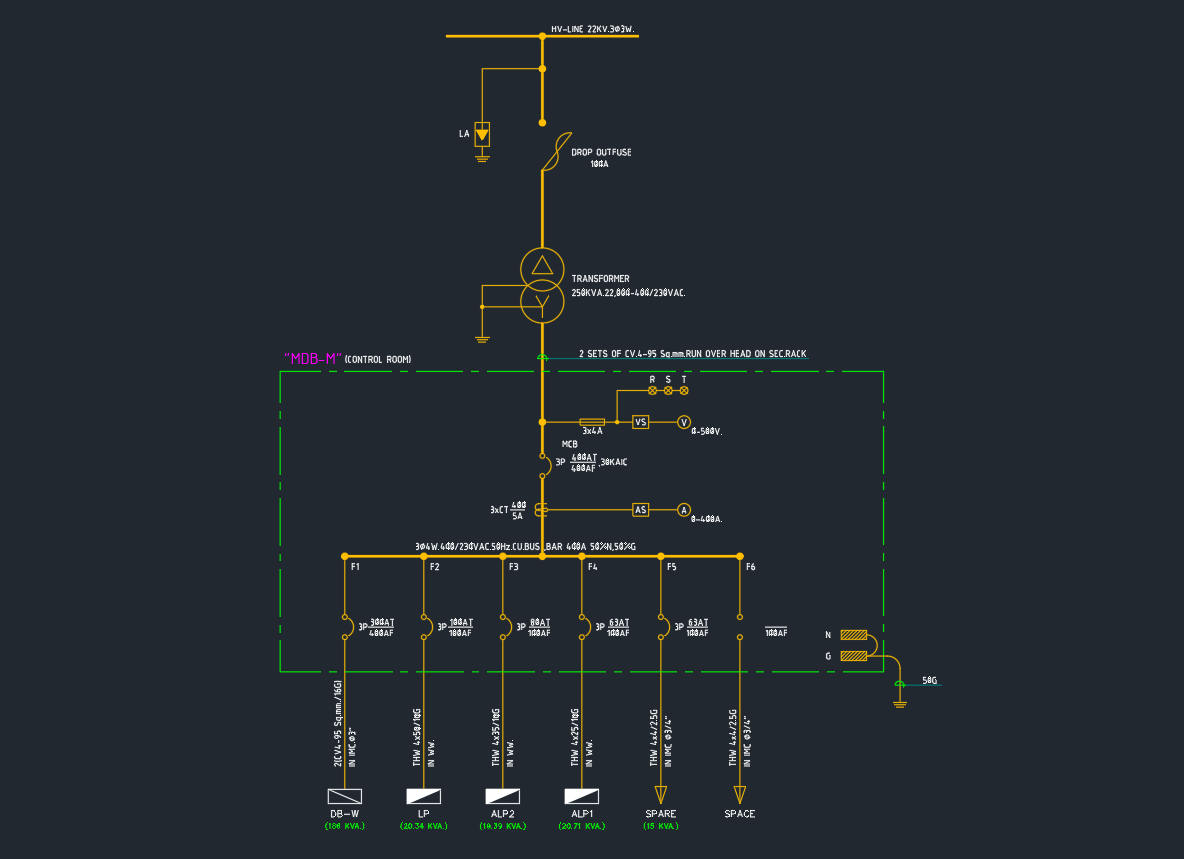
| Single-line diagram | Showing grounding relationships associated with services, transformers, generators, switchboards, and distribution equipment | May not show physical location or routing |
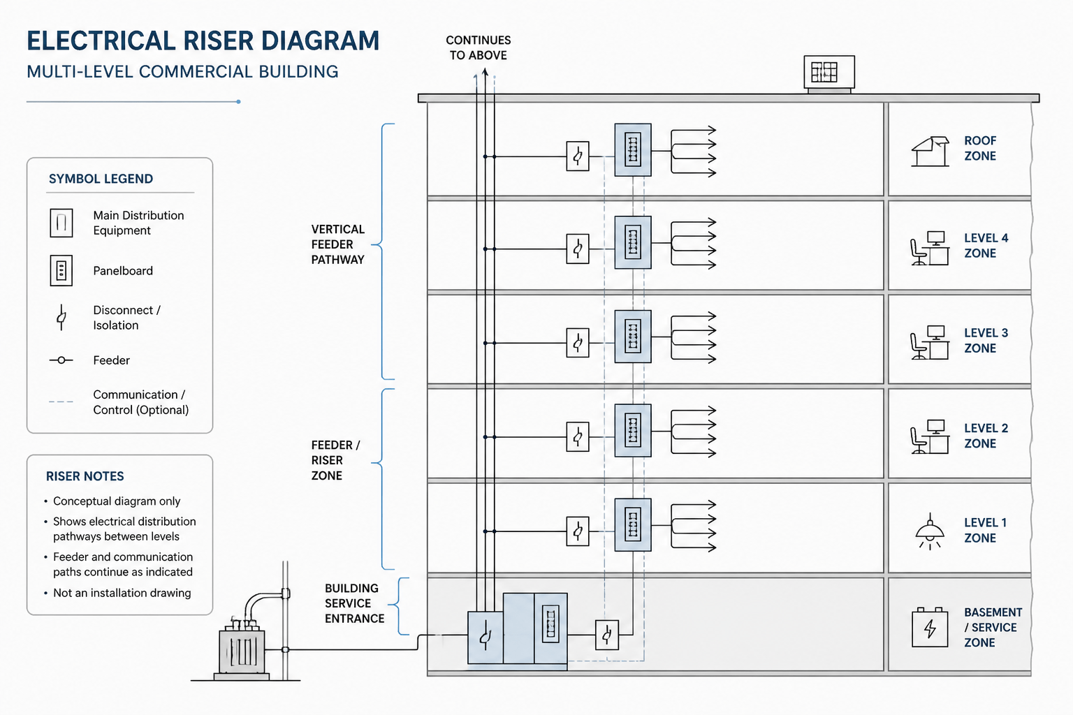
| Grounding riser or schematic | Presenting system relationships in a dedicated, simplified view | Can become abstract if equipment tags are missing |
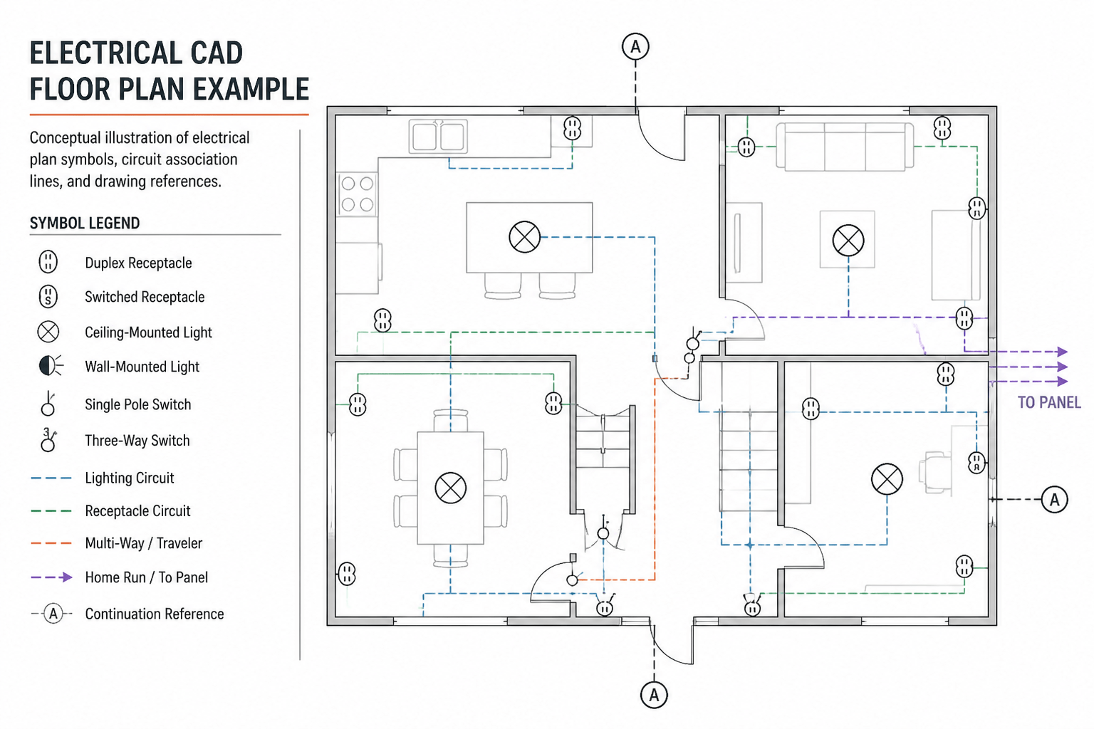
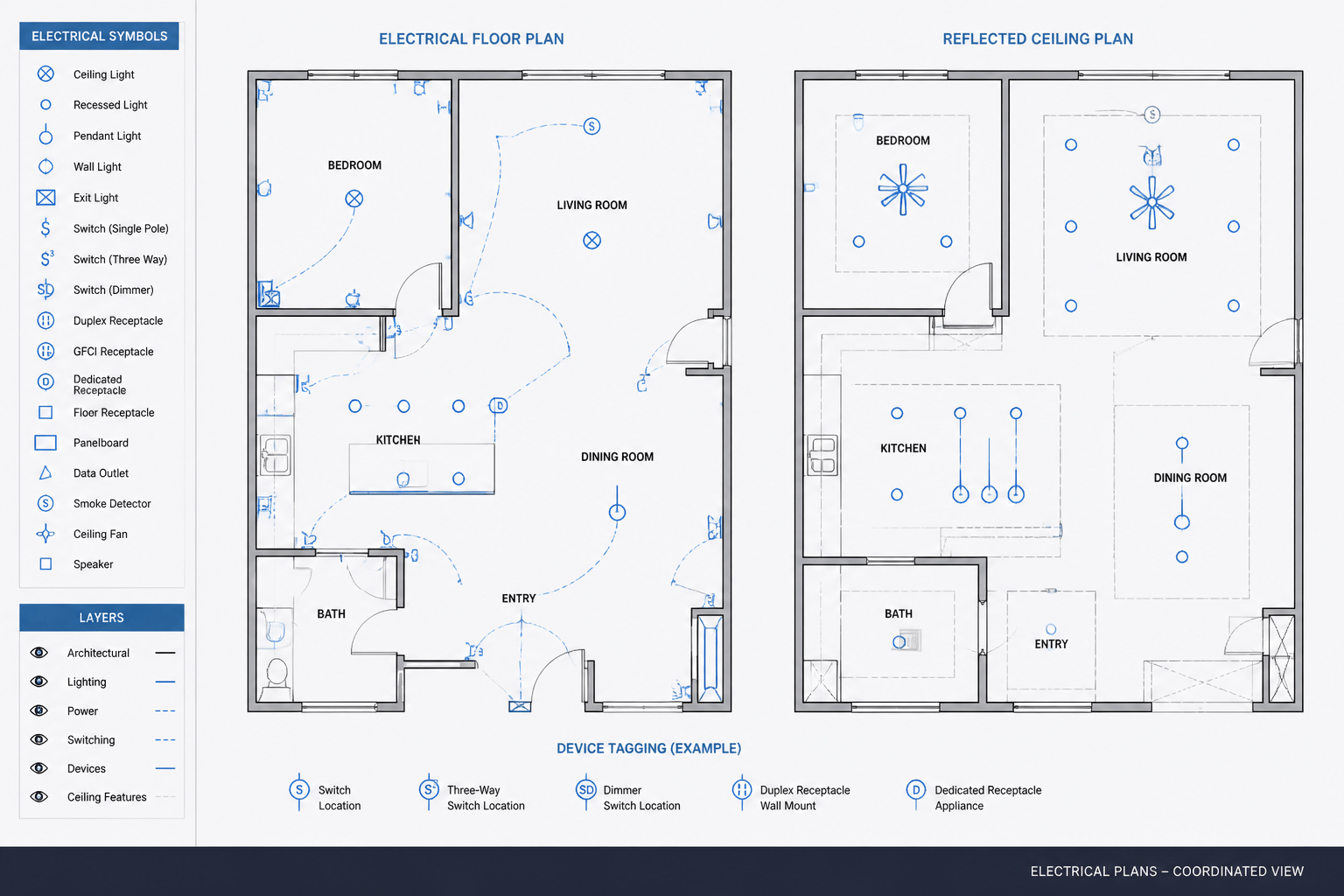
| Floor or site plan | Locating electrodes, grounding bars, equipment, test points, or routed conductors | Background geometry may obscure system intent |
| Installation detail | Clarifying a particular connection concept or interface | Does not communicate the complete system |
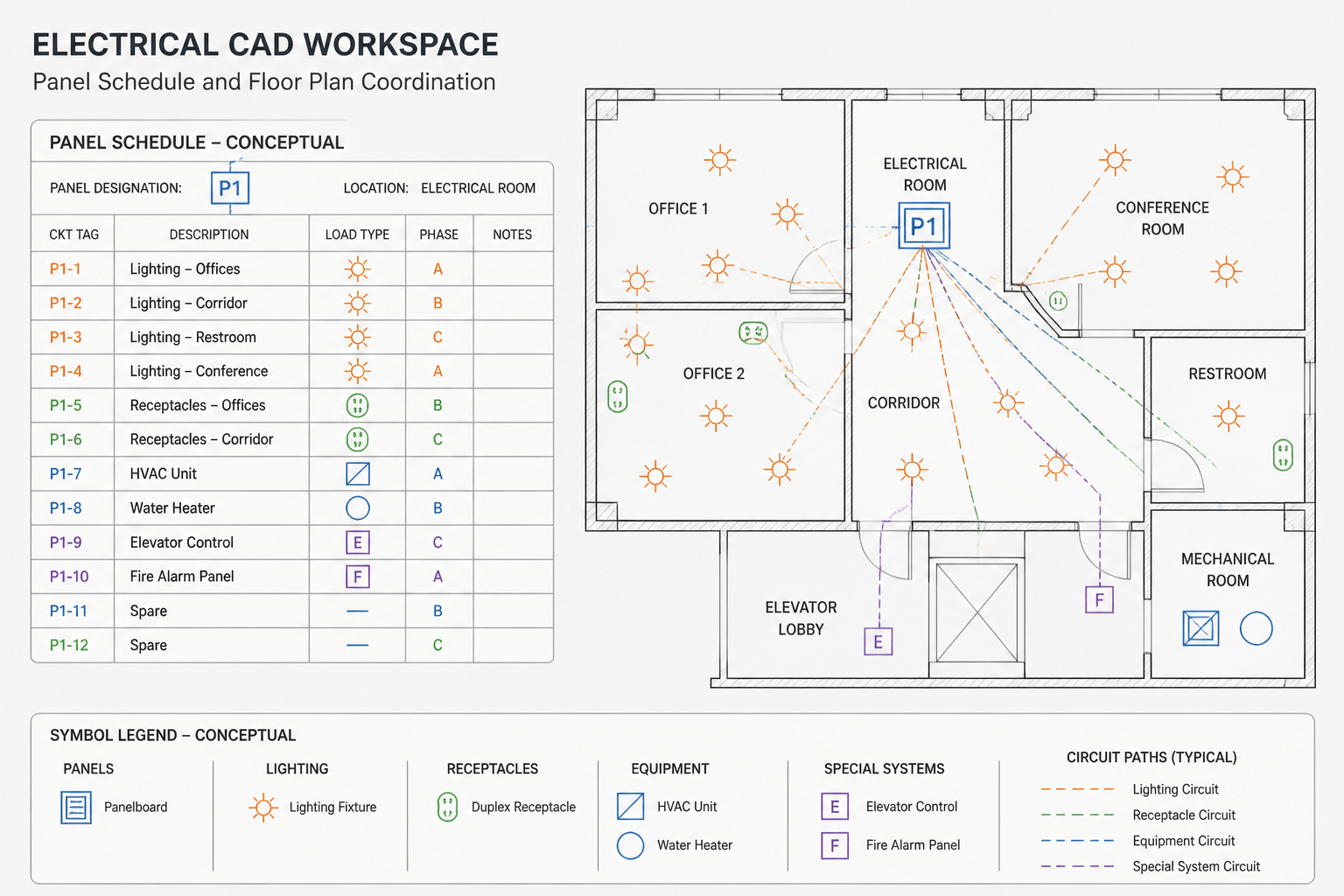
| Schedule | Organizing conductor, endpoint, source, or connection information | Requires coordinated tags on other drawings |
Many projects need more than one format. A schematic can explain the overall grounding and bonding concept, while plans establish locations and details clarify selected interfaces. These views should complement rather than repeat or contradict one another.
Define the diagram scope before drafting
Start with a short list of what the diagram must communicate. Depending on the project, the scope may include:
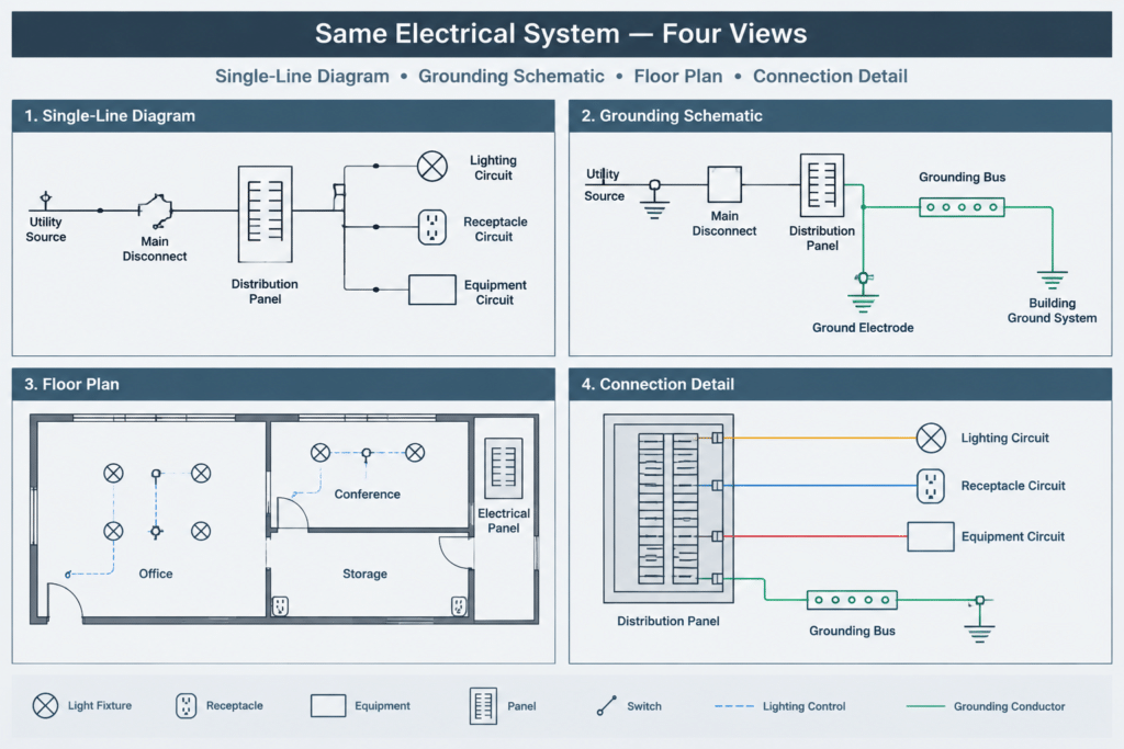
- Service equipment and its documented grounding point
- Main and downstream distribution equipment
- Transformers or other separately derived systems
- Generators, transfer equipment, or alternate power systems
- Grounding electrodes represented in the project documents
- Equipment grounding and bonding paths
- Grounding bars or busbars with unique tags
- Structural, piping, communications, lightning protection, or other interfaces when they are part of the design scope
- References to plans, schedules, notes, and enlarged details
Do not add a system merely because it commonly appears on similar projects. First confirm that it exists, falls within the drawing scope, and has a defined design relationship.
Build a consistent symbol and line system
Separate equipment symbols from connection symbols
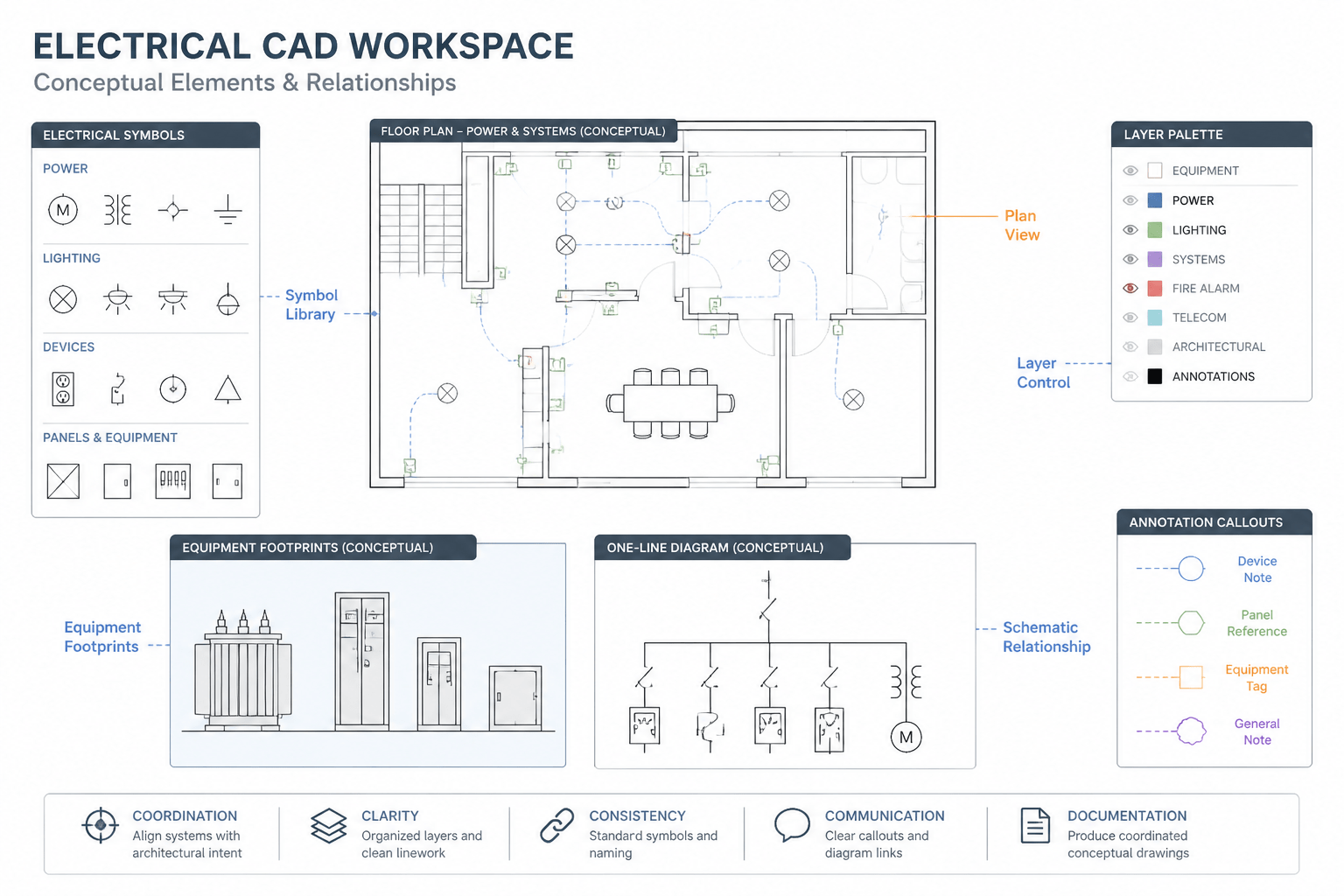
Equipment should use the same identifying tags found on the single-line diagram, plans, and schedules. A switchboard, transformer, generator, grounding bar, or panel should not receive a different abbreviation solely for the grounding drawing.
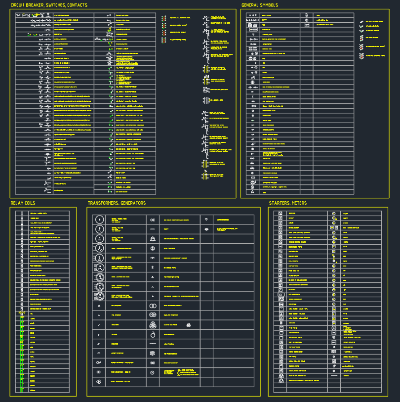
Connection symbols should be visually distinct from equipment outlines. Use a controlled symbol set for grounding electrodes, grounding bars, connection points, earth references, and continuation markers. If two symbols appear similar, add a label rather than relying on small graphical differences.
Use line types with a defined meaning
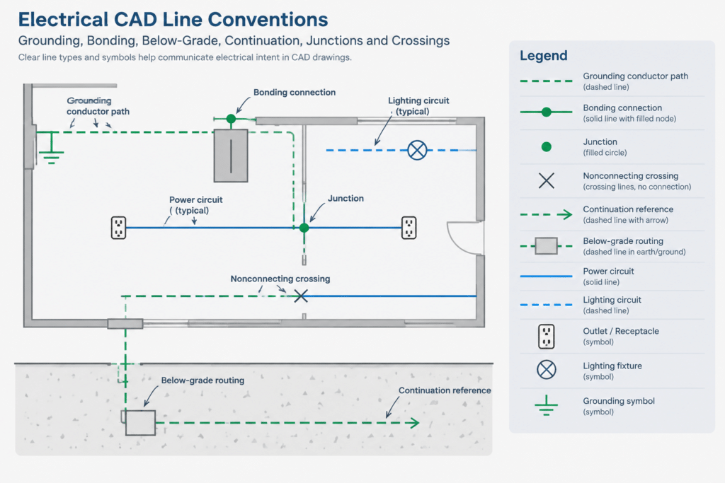
A grounding and bonding diagram may use different line conventions for conductor paths, bonding relationships, below-grade routing, or connections shown only for reference. The exact graphic convention is less important than consistency and a clear legend.
Avoid using color as the only distinction. Printed sets, monochrome PDFs, and field copies may not preserve layer colors. Linetype, annotation, endpoints, and lineweight should carry the meaning.
Show intentional endpoints
Every line should terminate at a labeled item, a recognized symbol, or a continuation reference. Lines that stop near equipment can create uncertainty about whether a connection is intended to reach an enclosure, internal bus, grounding bar, electrode, or adjacent system.
Organize the CAD drawing for maintainability
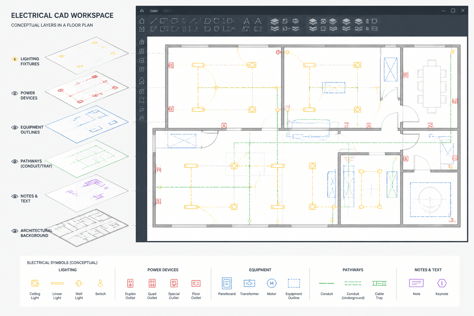
Place grounding graphics on dedicated layers that fit the project CAD standard. Useful separations may include equipment, grounding paths, bonding paths, symbols, tags, notes, and reference backgrounds. Avoid placing all grounding content on a single miscellaneous electrical layer.
Use blocks for repeated symbols, but keep their insertion points and orientation logical. Attributes can hold identifiers such as equipment tags, grounding bar names, or detail references. Attribute fields should support coordination, not store unverified engineering data.
If the diagram references architectural, structural, civil, or mechanical backgrounds, attach them as controlled references rather than copying geometry into the electrical file. A schematic diagram may not need a background at all. Removing unnecessary geometry often makes the electrical relationships much clearer.
Draft the system from source to endpoints
A practical workflow is to begin with the source or service relationship and work outward through the distribution system. Place major equipment first, using the same left-to-right or top-to-bottom reading direction throughout the sheet. Then add grounding and bonding paths, followed by labels, notes, and cross-references.
At each connection, ask three questions:
- What two components does this line connect?
- What type of relationship does the line represent?
- Where can the reader find additional location or installation information?
If the answer is not evident from the drawing, add a tag, concise note, line designation, or detail reference. Avoid long notes repeated at every endpoint; use a keyed note or schedule when one instruction applies in multiple locations.
Coordinate the diagram with related drawings
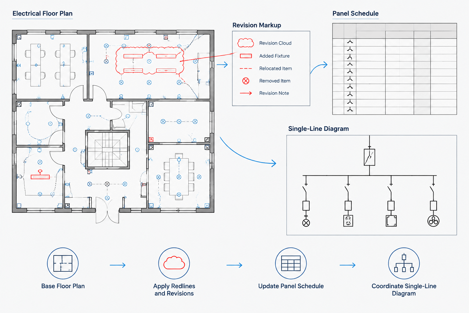
The grounding and bonding diagram should be checked against the electrical single-line diagram first. Equipment identifiers, source relationships, and distribution hierarchy should match. If a transformer appears on one drawing but not the other, determine whether the omission is intentional.
Next, compare the diagram with plans and equipment layouts. Verify that grounding bars, electrodes, major equipment, and connection points shown schematically can be located elsewhere in the set when location is relevant.
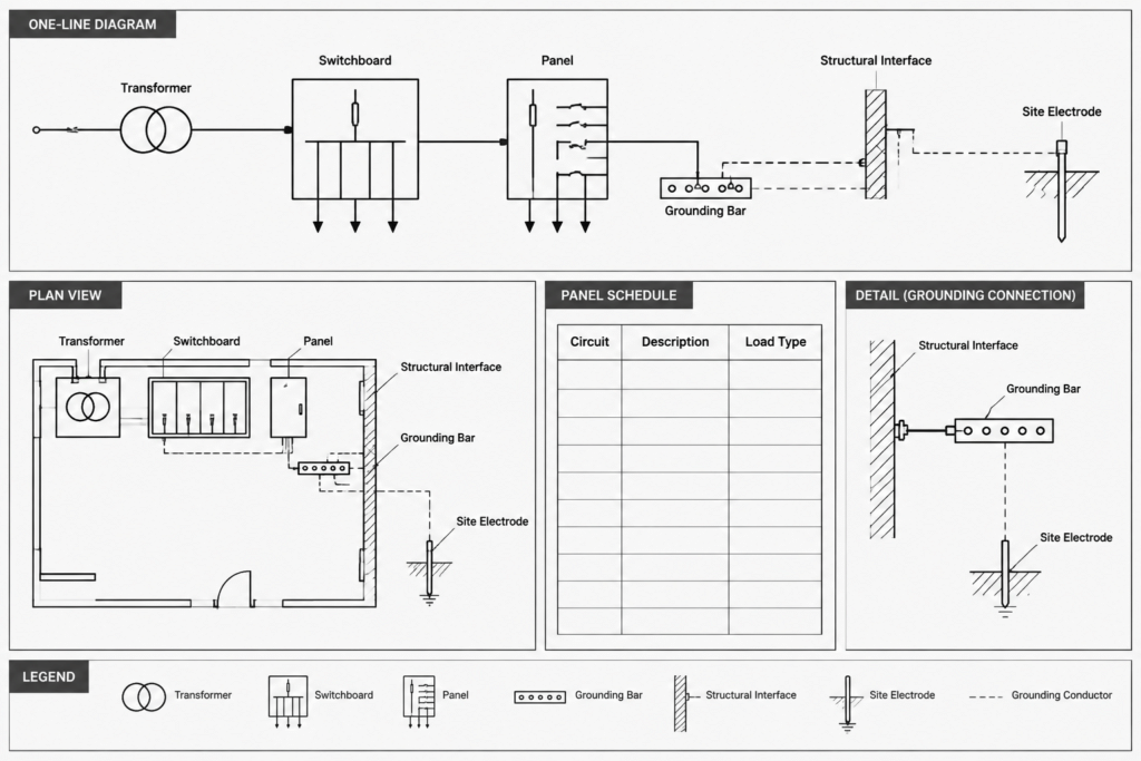
Also review other disciplines. Structural drawings may identify steel or foundation elements. Civil drawings may show site utilities and below-grade work. Mechanical and plumbing drawings may contain systems referenced by bonding notes. Communications and lightning protection documents may show interfaces that require clearly defined scope boundaries. Coordination does not mean drawing another discipline’s entire system; it means documenting the interface without leaving ownership ambiguous.
Use notes without hiding the design
General notes are useful for recurring drafting conventions and broad scope statements. They should not carry all of the diagram’s essential meaning. A note such as bonding all applicable equipment does not tell the reader which components are included, where a connection is represented, or how the diagram relates to the plans.
Prefer direct labels at critical connections. Use keyed notes for repeated conditions and reserve general notes for information that genuinely applies throughout the drawing. Requirements that depend on equipment selection or project conditions should be identified for verification rather than presented as universal.
Common drafting problems to avoid
- Using the earth symbol everywhere: Repetition can imply separate earth connections where the design intends a coordinated grounding system.
- Leaving conductors unlabeled: Similar-looking lines can represent different functions.
- Mixing physical and schematic routing: State whether conductor paths are diagrammatic or intended to convey location.
- Duplicating conflicting notes: Keep shared information in a controlled location and cross-reference it.
- Breaking equipment tag coordination: Tags must match plans, schedules, details, and one-lines.
- Overloading a single diagram: Split complex systems into logical views or use enlarged details.
- Showing unverified interfaces: Do not assume structural, piping, lightning protection, or communications connections without design confirmation.
Final CAD quality-control review
Before issue, trace each documented path visually from its origin to its endpoint. Confirm that lines do not disappear behind blocks, terminate in empty space, or cross in ways that imply unintended connections. Check that junctions and nonconnecting crossings are graphically distinguishable.
Compare every equipment tag with the latest one-line, plans, and schedules. Review the symbol legend, note references, detail callouts, and sheet references. Plot the drawing in its intended output style to confirm that lineweights, linetypes, text, and symbols remain readable without relying on color.
Finally, have the responsible design professional verify the technical content. A clean CAD file improves communication, but graphical consistency alone cannot establish whether a grounding or bonding arrangement is correct for a particular project.
Leave a Reply
You must be logged in to post a comment.