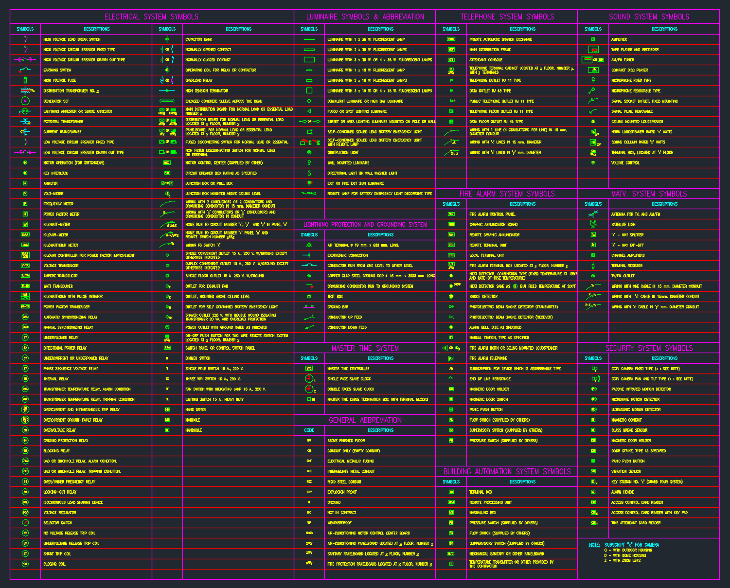
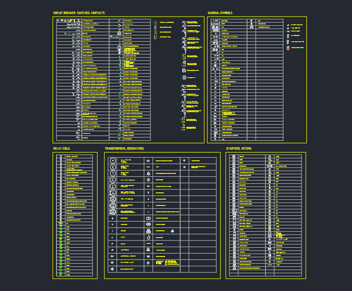
An Electrical System Symbols DWG can help organize recurring drafting elements for schematics, wiring diagrams, and electrical layouts. This downloadable CAD block collection is intended for architects, engineers, and designers who need reusable symbols in an AutoCAD-compatible workflow.
Use the file as a drafting reference, then coordinate each symbol with the project legend, drawing conventions, and applicable engineering documentation. Clear symbol use helps readers distinguish electrical intent from architectural backgrounds, equipment layouts, and other plan information.
Discover a comprehensive collection of **Electrical System Symbols** with this high-quality DWG file, perfect for architects, engineers, and designers. This CAD Block set includes a variety of standard electrical symbols commonly used in electrical schematics and wiring diagrams, ensuring your projects meet industry standards. The file is fully compatible with AutoCAD and other major CAD software, allowing seamless integration into your design workflow. Ideal for residential, commercial, and industrial projects, these symbols streamline the drafting process and enhance the clarity of your electrical layouts. Download now to elevate your engineering documentation.
Please log in or register to download this file.
How to use electrical system symbols in CAD drawings
Electrical symbols communicate the function or identity of components without requiring every item to be drawn in pictorial detail. In a CAD environment, reusable blocks can improve consistency across plans, schematics, and wiring diagrams while reducing repetitive drafting work.

Organize symbols by drawing purpose
- Schematic documentation: Use symbols to represent relationships and circuit intent in a clear, readable arrangement.
- Wiring diagrams: Coordinate symbols with connecting lines, conductor references, and the project’s documentation convention.
- Electrical layouts: Place symbols in relation to rooms, equipment, panels, lighting elements, and other architectural or engineering information.
- Coordination drawings: Check symbol visibility, layer organization, annotation, and alignment with the rest of the CAD file.
Reference checks before issuing a drawing
Before using a symbol in a final set, compare it with the project legend and confirm that its meaning is unambiguous at the intended drawing scale. Review block insertion behavior, layer assignment, orientation, lineweight appearance, and annotation compatibility. These checks are especially useful when combining electrical symbols with panel schedules, distribution documentation, cable and conduit drafting, or lighting and power plans.
The downloadable DWG is a drafting resource rather than a substitute for design verification. Engineers and responsible design professionals should confirm the interpretation, coordination, and compliance of electrical documentation for the specific project.
Related electrical CAD reference topics
This symbol collection can be used alongside electrical legends, single-line diagram concepts, panel and distribution drawings, equipment layouts, and cable or conduit drafting references. Keeping these topics coordinated helps produce drawings that are easier to review, revise, and use during project documentation.

Frequently asked questions
What is an Electrical System Symbols DWG?
It is a CAD drawing file containing reusable electrical symbols for drafting applications such as schematics, wiring diagrams, and electrical layouts.
Can the DWG be used with AutoCAD?
Yes. The source file is described as compatible with AutoCAD and other major CAD software. Always confirm file behavior in the CAD application and project template used by your team.

Are these symbols a replacement for an electrical legend?
No. A symbol collection supports drafting, but the project legend remains important for defining how symbols are interpreted in a particular drawing set.
Can I use the symbols in residential, commercial, and industrial documentation?
The source describes the collection as suitable for residential, commercial, and industrial projects. Review each symbol against the project requirements, drawing standards, and responsible engineer’s direction before issuing documentation.
What should I check after inserting a CAD block?
Check its orientation, layer, visibility, lineweight, annotation, and coordination with nearby architectural and electrical information. Also verify that the symbol remains legible in the final plotted drawing.




Leave a Reply
You must be logged in to post a comment.