Coordinate the data, not only the table
Electrical panel schedule coordination in CAD is a drawing-set quality-control process. The schedule, circuit tags, equipment references, panel names, status notes, and distribution diagrams must remain aligned as the design changes. A schedule that looks complete can still be unreliable when its entries cannot be traced to the plans or when its panel designation conflicts with another document.
The guidance below focuses on managing those drawing relationships from initial circuit tagging through final issue review. It does not treat a generic schedule, imported table, or copied project file as approved design data. Circuit assignments, calculations, protective-device information, and other technical content remain subject to the project team’s verification and approval process.
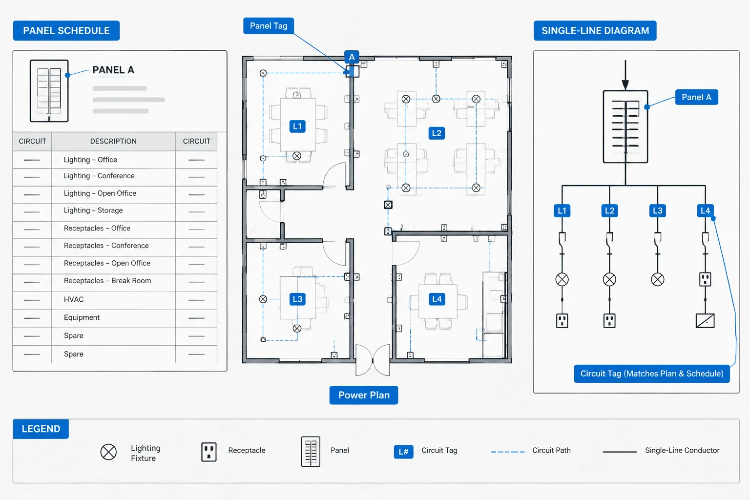
An electrical panel schedule is more than a table placed on a drawing sheet. It is a project data record that connects panel identification, circuit assignments, connected equipment, load descriptions, and distribution documentation. When that information is not coordinated, a floor plan may reference a circuit that does not appear in the schedule, a one-line diagram may use a different panel name, or a revision may update the plan without updating the associated table.
Effective electrical panel schedule coordination begins with a controlled information workflow. CAD geometry, schedule cells, device tags, equipment connection data, and diagram labels should all describe the same design intent. This guide explains how to organize that workflow without treating a generic schedule or CAD block as verified project data.
What a panel schedule coordinates
A panel schedule commonly identifies the panel and organizes its outgoing circuits. Depending on the project and documentation method, it may also include load descriptions, circuit status, connected equipment references, protective-device information, phase allocation, notes, and summary information.
The exact content should follow the project requirements and the design team’s approved documentation practices. A downloaded schedule template can provide a useful graphic starting point, but its headings, circuit arrangement, calculations, and technical fields must be checked before use.
Panel schedules usually coordinate with several drawing sources:
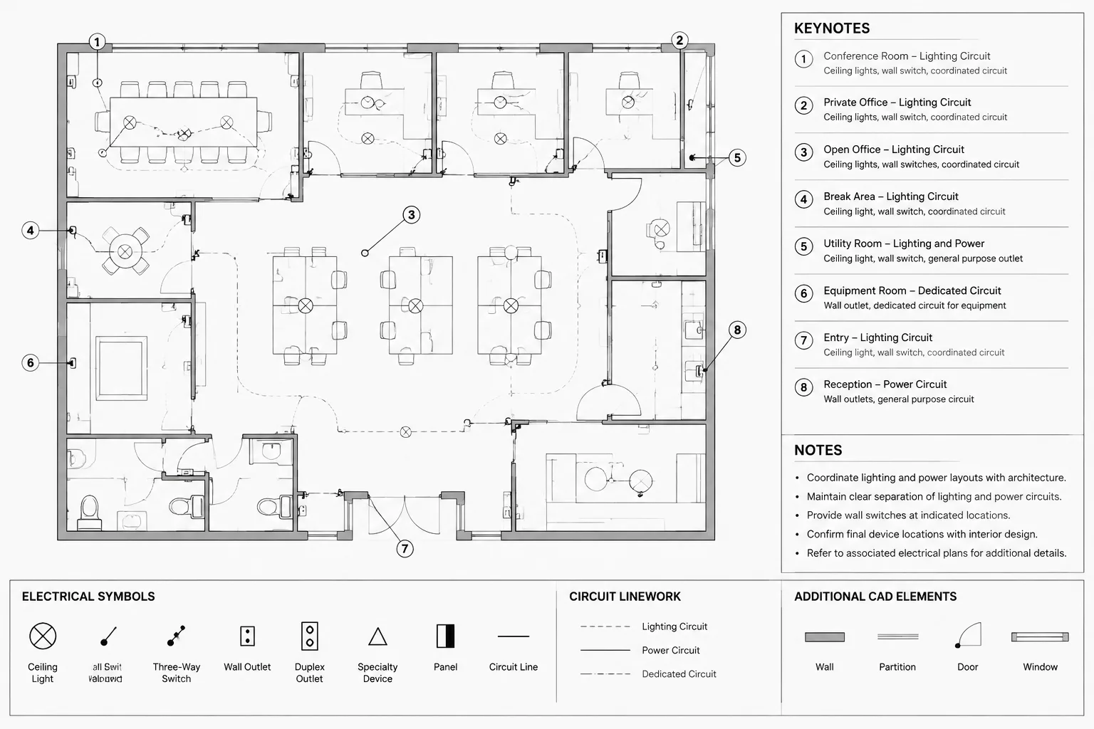
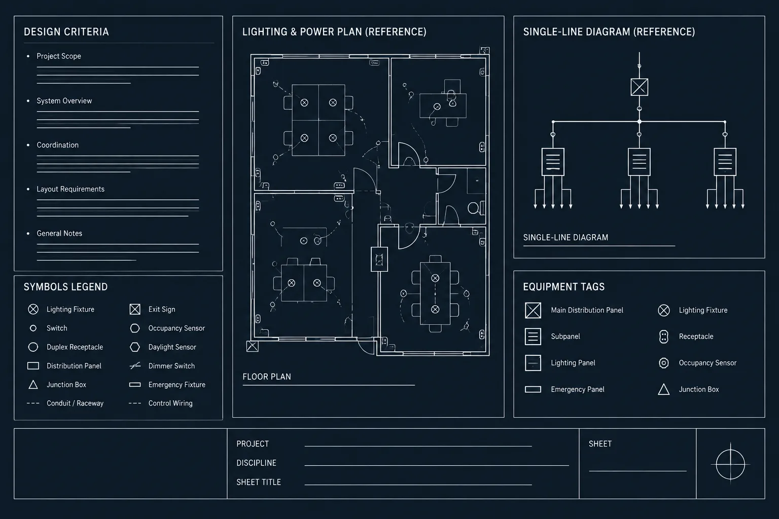
- Power and lighting plans: Device tags and home-run annotations identify the serving panel and circuit.
- Single-line diagrams: The panel appears within the distribution hierarchy and is connected to its source.
- Equipment connection schedules: Mechanical, plumbing, process, or specialty equipment may be assigned to panel circuits.
- Load summaries: Panel data may contribute to broader distribution calculations and summaries.
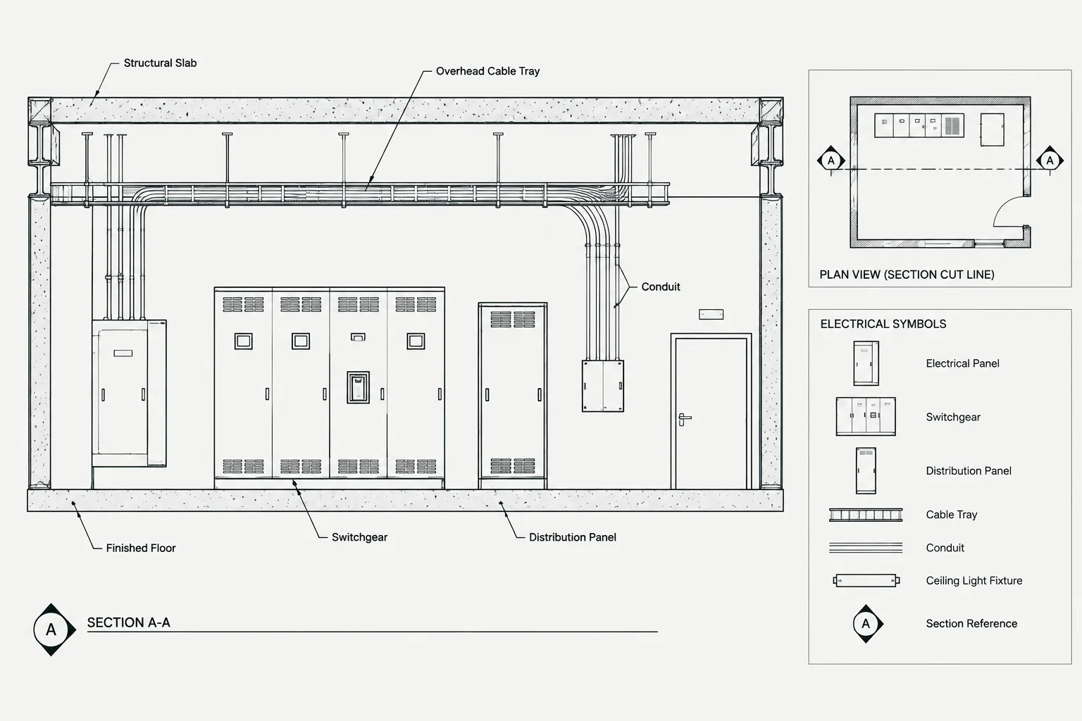
- Equipment plans and elevations: The panel location, designation, and physical coordination are documented.
- Demolition and renovation plans: Existing circuits may be removed, reused, extended, or reassigned.
Establish the panel identity before populating circuits
Panel identification should be stable before detailed circuit assignments are developed. A panel name functions as a cross-reference key throughout the drawing set. Minor differences in punctuation, spacing, prefixes, or abbreviations can cause failed searches and misleading comparisons.
Create a controlled panel list that records each designation and its drawing relationships. At a minimum, the drafting team should be able to determine where the panel is shown on plan, where it appears on the one-line diagram, and which schedule belongs to it. If the project uses separate identifiers for equipment tags and display names, document that distinction rather than switching between them informally.
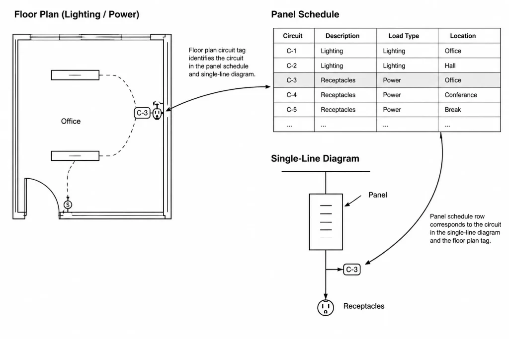
Panel names should not be changed in only one location. A rename may affect schedule titles, circuit tags, one-line labels, equipment schedules, detail callouts, keynotes, and external data files. Treat a rename as a coordinated revision.
Build a reliable circuit-description workflow
Circuit descriptions should help a reviewer understand what is served without forcing a search through every floor plan. Generic entries such as “receptacles” or “lighting” may be insufficient when several rooms, zones, or equipment groups are involved. At the same time, descriptions should remain concise enough to fit the schedule clearly.
A practical naming pattern may combine the served area with the load or system function. The drafting team should use consistent room names, equipment tags, and abbreviations already established elsewhere in the set. Do not introduce a shortened equipment name in the panel schedule if the plan and equipment schedule use a different tag.
Descriptions also require careful treatment when a circuit serves multiple locations. The schedule can summarize the connected scope, while plans show the exact device locations. Avoid using the schedule as a substitute for plan circuiting, and avoid overloading plan tags with descriptions that belong in the schedule.
Coordinate status terminology
Terms such as existing, new, spare, space, future, relocated, and removed can represent different conditions. They should not be treated as interchangeable. Use project-defined terminology consistently and make the graphical distinction clear in renovation work.
For example, an unused installed circuit position is not necessarily the same as an uninstalled position reserved within the panel arrangement. Similarly, a future load should not be presented as though it is part of the current construction scope. The schedule, notes, one-line diagram, and plans should communicate the same status.
Choose a CAD schedule method deliberately
Panel schedules may be drafted as linework and text, built with CAD table objects, generated from external data, or produced through a project-specific automation system. Each method has coordination implications.

| Method | Useful characteristics | Coordination risks |
|---|---|---|
| Lines and text | Simple appearance and direct graphic control | Manual edits can create misaligned rows, duplicated values, or missed updates |
| CAD table | Structured rows, columns, and consistent cell formatting | Imported styles or overrides may plot differently across files |
| Linked external data | Can support shared editing and repeatable updates | Broken paths, stale links, and conflicting edits require management |
| Automated project data | Can reduce repeated entry when configured correctly | Output remains dependent on verified source data and mapping rules |
The best method is the one the project team can maintain reliably. Automation does not remove the need for review. A perfectly formatted schedule can still contain incorrect panel names, circuit assignments, or load descriptions.
Keep schedule graphics readable and editable
Schedule presentation should support rapid scanning. Use a clear title area, consistent column headings, aligned entries, and a text hierarchy that remains legible when plotted. Avoid crowding technical information into narrow cells merely to fit an arbitrary schedule width.
Place schedules in a predictable sheet location and organize them so related panels are easy to find. If a schedule continues in another location, use an explicit continuation reference. Do not create two independent partial copies of the same panel schedule unless the project workflow clearly controls which copy is authoritative.
Layering also matters. Schedule borders, headings, body text, notes, and revision graphics may require different plotting behavior. Follow the project CAD standard rather than importing uncontrolled layers with a downloaded table or block. Check that text styles, lineweights, and cell margins remain readable in the final plotted output.
Coordinate plans with the schedule in both directions
Plan-to-schedule review finds circuit tags that have no corresponding schedule entry. Schedule-to-plan review finds listed circuits that cannot be located on the plans. Both directions are necessary.
A useful review sequence is:

- List every panel represented by a schedule.
- Confirm that each scheduled panel appears in the distribution documentation.
- Search the CAD files or published PDFs for each panel designation.
- Compare plan circuit tags with the corresponding schedule rows.
- Confirm that equipment tags in circuit descriptions match the equipment schedules and plans.
- Review circuits described as spare, future, existing, or removed against the project scope.
- Investigate duplicate circuit references, blank descriptions, and temporary drafting notes.
Text searches are helpful but not conclusive. A panel name may appear in a general note, demolition note, or detail that is unrelated to a live circuit assignment. Visual review is still required.
Manage revisions without losing circuit history
Panel schedules are especially vulnerable to late changes because circuit assignments may shift as equipment and room layouts develop. A single inserted load can affect several adjacent schedule entries, plan tags, and home-run labels.
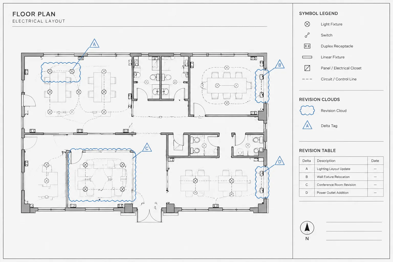
Before rearranging circuits, determine what has already been issued and which references will be affected. Maintain a review record that identifies changed descriptions, added or removed loads, reassigned circuits, and renamed panels. Revision clouds may show where a schedule changed, but they do not replace coordination with plans and diagrams.
Avoid using color alone to distinguish revised schedule content because color may not survive monochrome plotting or document export. Use the project’s established revision methods and verify the published PDF, not only the editable CAD view.
Common panel schedule coordination failures
- Orphaned circuit tags: A plan references a panel or circuit that is absent from the schedule.
- Orphaned schedule entries: A load remains listed after its plan symbol or equipment connection is removed.
- Inconsistent panel names: The schedule, one-line diagram, and plan use slightly different designations.
- Uncontrolled abbreviations: A circuit description cannot be matched confidently to a room or equipment tag.
- Copied legacy data: A schedule duplicated from another panel retains incorrect titles, notes, or descriptions.
- Conflicting status notes: A circuit is labeled existing in one view and new in another.
- Stale linked data: The plotted schedule does not reflect the current external source.
- Unreadable output: Text fits in model space but clips, wraps poorly, or becomes too small on the issued sheet.
Final issue checklist
Before issuing the drawing set, verify that panel schedule information is internally consistent and traceable. Check schedule titles, panel designations, circuit descriptions, equipment references, status terminology, continuation references, and revision marks. Compare the schedules with the plans, one-line diagrams, equipment schedules, and load documentation used by the project.
Finally, publish the sheets using the intended plot settings and review the resulting documents. Look for missing fonts, clipped text, broken table borders, unexpected lineweights, stale data links, and poor searchability. The goal is not merely a complete-looking table; it is a dependable coordination record that helps readers move confidently between the panel schedule and the rest of the electrical drawing set.
Define ownership for repeated panel data
A coordinated drawing set often repeats the same information in several places. To prevent competing versions, establish which project record is the approved editing source for each data field and which views are dependent references. The authoritative location may differ by field rather than being one universal file.
A simple coordination register can identify:
- Data field: The panel designation, circuit assignment, load description, equipment tag, or status term being controlled.
- Approved source: The schedule, plan, diagram, equipment record, or managed project dataset from which dependent references are updated.
- Dependent locations: Every plan tag, table, diagram label, note, or callout that repeats the information.
- Editing responsibility: The drafting or design role responsible for initiating and checking the update.
- Review trigger: The type of revision that requires another coordination check.
Data ownership is a documentation-control concept, not a substitute for engineering review. Its purpose is to make changes traceable and prevent separate team members from editing repeated values independently.
Use an exception list during issue review
Broad instructions such as “check the schedules” can leave unresolved discrepancies hidden in the drawing set. An exception list gives reviewers a focused record of items that require a decision. Useful exception categories include unmatched circuit tags, schedule entries without a plan reference, inconsistent panel names, ambiguous abbreviations, conflicting status terms, copied notes, and changes that have not reached every dependent view.
Each exception should receive a documented disposition rather than being removed from the list without explanation. The resolution may involve correcting a drafting error, confirming an intentional difference, referring the question to the responsible designer, or holding the item for an approved revision. This approach separates verified coordination from assumptions made only to complete the table.
Review the issued deliverable
The editable CAD file is not the final coordination test. Review the published drawing package using the intended plotting and export workflow. Confirm that schedule text remains legible, searchable references return meaningful results, revision graphics are visible, and linked or generated content reflects the approved project state.
Where practical, compare the published schedule against the project exception list before closing the review. This final comparison helps confirm that resolved items reached the deliverable rather than remaining only in a working file or external data source.
Frequently asked questions
What should control when a plan tag and panel schedule conflict?
Do not assume that either location is automatically correct. Check the project’s designated source for that data field, review related diagrams and equipment records, and refer unresolved conflicts to the responsible designer. The correction should then be carried through every dependent drawing location.
How can drafters find circuit tags that are missing from a schedule?
Search the drawing files or published documents for the panel designation, compare the resulting circuit references with the schedule, and visually inspect the associated plans. Text searches support the review, but they may also find notes or details that are not actual circuit assignments.
Can a downloaded CAD panel schedule be used directly?
A downloaded schedule can be a graphic starting point, but its titles, fields, styles, notes, circuit arrangement, and embedded data require project-specific review. Remove inherited content that cannot be verified and align the table with the current CAD standard before relying on it.
How should a panel rename be handled?
Treat the rename as a coordinated revision. Search schedules, plans, single-line diagrams, equipment records, callouts, notes, and managed data sources for the former designation. Review the published output afterward to catch references that were not updated.
Are spare, space, and future interchangeable schedule terms?
No. They can communicate different installed or planned conditions. Use the terminology defined for the project and confirm that the schedule, plans, notes, and distribution documentation express the same status.
Why is a bidirectional review necessary?
Checking plans against schedules reveals tags without matching entries, while checking schedules against plans reveals entries that no longer have a visible load or connection. Performing only one direction can leave orphaned information undiscovered.


Leave a Reply
You must be logged in to post a comment.