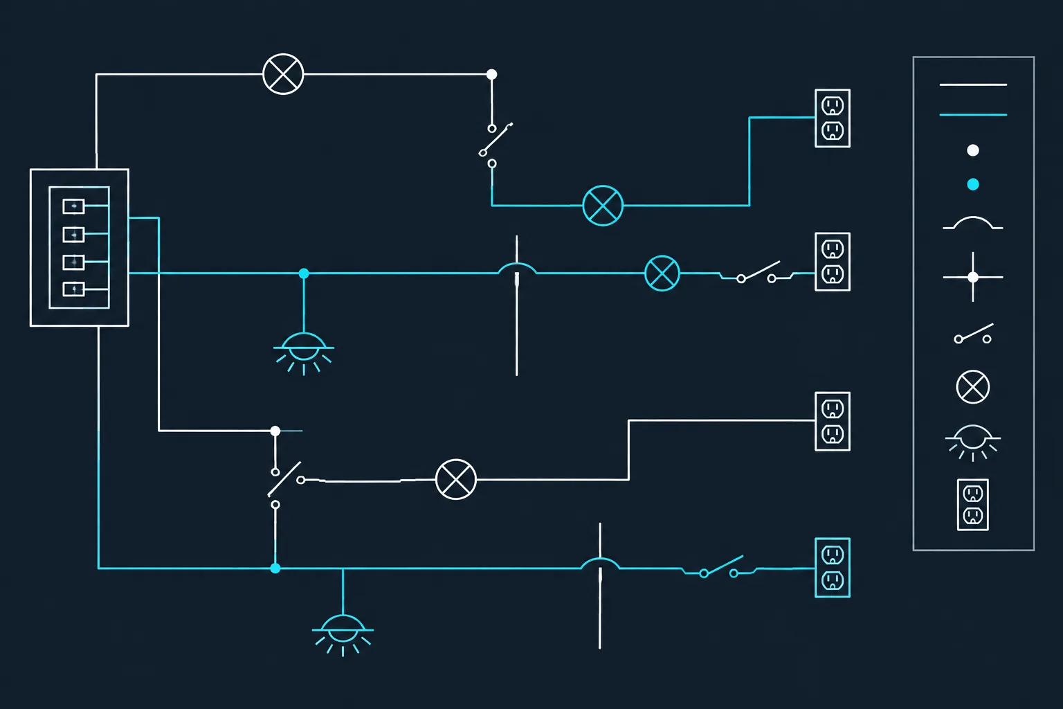
Connection clarity is a core part of electrical diagram quality. A crossing that appears obvious while editing may become uncertain after plotting, exporting, scaling, or combining drawings from different sources. This reference helps CAD users distinguish graphical contact from intended electrical connectivity and evaluate whether each intersection communicates the correct relationship.
Use the guidance alongside the project legend, CAD standards, and verified design information. The objective is not merely consistent-looking linework, but a diagram in which reviewers can trace connected paths without having to infer the drafter’s intent.
Electrical diagrams often contain conductors, signal paths, control wires, and feeder lines that must cross on the page. The difficult part is not drawing the lines; it is making their electrical relationship unmistakable. A crossing may represent a connection, an intentional nonconnection, or simply a drafting conflict caused by crowded routing.
Ambiguous electrical diagram line crossings can create confusion during design review, estimating, fabrication, installation, and troubleshooting. CAD users can reduce that risk by applying a consistent graphical convention, organizing linework carefully, and checking every crossing as part of drawing quality control.
This guide explains the main crossing methods and provides a practical workflow for schematics, wiring diagrams, interconnection diagrams, control diagrams, and single-line diagrams. It is a drafting reference, not a substitute for project requirements or engineering verification.
Why Line Crossings Require Special Attention
A line in an electrical diagram represents a relationship rather than a physical object at its plotted width. Depending on the drawing type, it may represent a conductor, cable, feeder, bus connection, control signal, communication path, or logical connection.
When two lines meet or cross, the reader needs to answer a basic question: are they electrically connected? If the graphic does not provide a clear answer, the reader may rely on assumptions from another drafting convention. That is especially risky when drawings come from multiple consultants, legacy files, vendor diagrams, or imported PDF backgrounds.
Crossings become harder to interpret when:
- Several lines converge in a small area.
- Junction dots are too small or obscured by lineweight.
- Nonconnecting lines merely pass through one another without a distinguishing mark.
- Text, device symbols, or masks cover part of a connection.
- Different sheets use different crossing conventions.
- A rasterized or low-quality plot hides small gaps and dots.
- Lines stop near one another without clearly touching or remaining separate.
Three Common Crossing Conditions
Connected lines
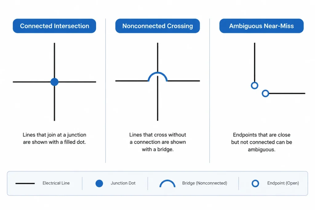
A connected crossing indicates that the represented conductors or paths join at that point. A filled junction dot is commonly used to make the connection visible. The dot should be centered on the intersection and remain recognizable at the intended plot scale.
A simple line intersection without a dot may also be treated as connected under some office or project conventions, particularly at a T-shaped branch. However, relying on line contact alone can be ambiguous when drawings move between organizations. If connection meaning is important, an explicit and consistently applied junction marker is generally easier to review.
Nonconnected crossing lines
A nonconnected crossing means that one represented path passes another without joining it. Common graphical treatments include a bridge or jump in one line, a deliberate gap, or an uninterrupted crossing interpreted according to the drawing legend.
No single treatment should be assumed to be universal. The chosen method needs to be defined for the project and used consistently across related sheets.
Near misses and accidental contacts
A near miss occurs when a line endpoint stops close to another line but does not clearly meet it. The opposite problem occurs when linework unintentionally touches because of object snaps, stretching, scaling, or block editing. These conditions may appear harmless on screen but look connected after plotting.
Near misses should not be used as a connection convention. A branch should either connect cleanly with the required junction graphic or remain visibly separated.
Comparing CAD Crossing Methods
| Method | Typical meaning | Drafting advantage | Review concern |
|---|---|---|---|
| Filled junction dot | Lines are connected | Provides an explicit connection marker | A small dot may disappear or become confused with other graphics |
| Bridge or line jump | Lines cross without connecting | Makes the passing relationship visually obvious | May add clutter when many crossings are close together |
| Deliberate line gap | Lines cross without connecting | Can produce a clean diagram when plotted clearly | Masks, background fills, or poor plotting may alter the apparent gap |
| Plain crossing with no dot | Meaning depends on the documented convention | Uses minimal graphic content | Readers may interpret it differently |
| T-shaped branch | Usually indicates a branch connection | Easy to follow when geometry is clean | A tiny endpoint gap can make the intended connection uncertain |
Select a Convention Before Drafting
The crossing convention should be established before a large diagram is developed. Check the project CAD manual, drawing legend, client requirements, and existing diagram sheets. Vendor or manufacturer diagrams may use a different convention, so they should not be inserted into a project set without review.
Document the selected convention in the legend when readers could reasonably encounter more than one interpretation. The legend should show graphical examples of both connected and nonconnected crossings rather than relying only on written descriptions.
Legacy drawings require extra caution. A familiar symbol or crossing method may have been used differently by the original author. Review surrounding devices, wire tags, terminal references, and continuation points to determine the intended relationship. Do not change the graphics merely for visual consistency until the electrical meaning has been verified.
A Practical CAD Drafting Workflow
1. Route for comprehension first
Arrange primary paths so the drawing can be followed naturally. Group related circuits and minimize unnecessary direction changes. Reposition devices or terminal groups when a small layout adjustment can eliminate several crossings.
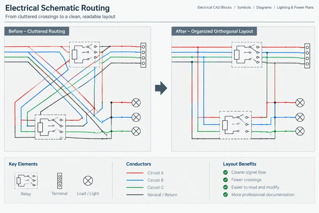
Automatic-looking line routing is not necessarily readable routing. A diagram may be geometrically tidy yet difficult to trace if unrelated paths overlap or repeatedly weave through one another.
2. Use orthogonal connection geometry consistently
Horizontal and vertical segments are generally easier to trace in dense electrical diagrams than arbitrary angled paths. Keep branch intersections aligned where practical, but avoid stacking unrelated crossings so closely that junction dots or bridges merge visually.
Use object snaps carefully. Endpoints intended to connect should terminate on the correct path. Nonconnecting lines should not share endpoints or contain accidental overlap segments.
3. Separate linework from crossing graphics
Place diagram paths and crossing markers on logically managed layers or within controlled block definitions. A junction dot can be a simple reusable symbol, while a bridge can be represented by consistent geometry appropriate to the office template.
Do not scatter manually drawn circles, trimmed fragments, and inconsistent arcs throughout the file. Reusable graphics make global updates and audits easier. Any block used for this purpose should be checked for unit behavior, insertion point, plot appearance, and compatibility with the diagram scale.
4. Avoid hiding connections with masks
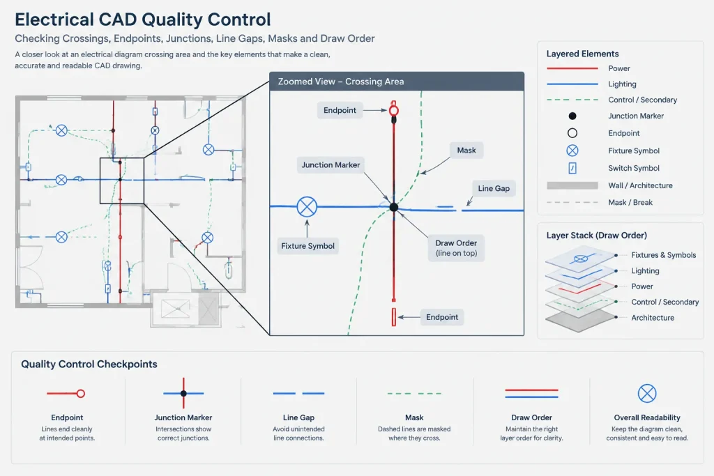
A bridge or gap may be produced with trimmed linework or controlled masking, but masks require careful management. A mask can hide nearby conductors, grid lines, device graphics, or text if its boundary is too large. Draw order changes can also alter the plotted result.
Inspect crossing graphics with all relevant layers visible and test them against the actual sheet background. A method that works on an empty model-space screen may fail when placed over other diagram content.
5. Add identification where routing alone is insufficient
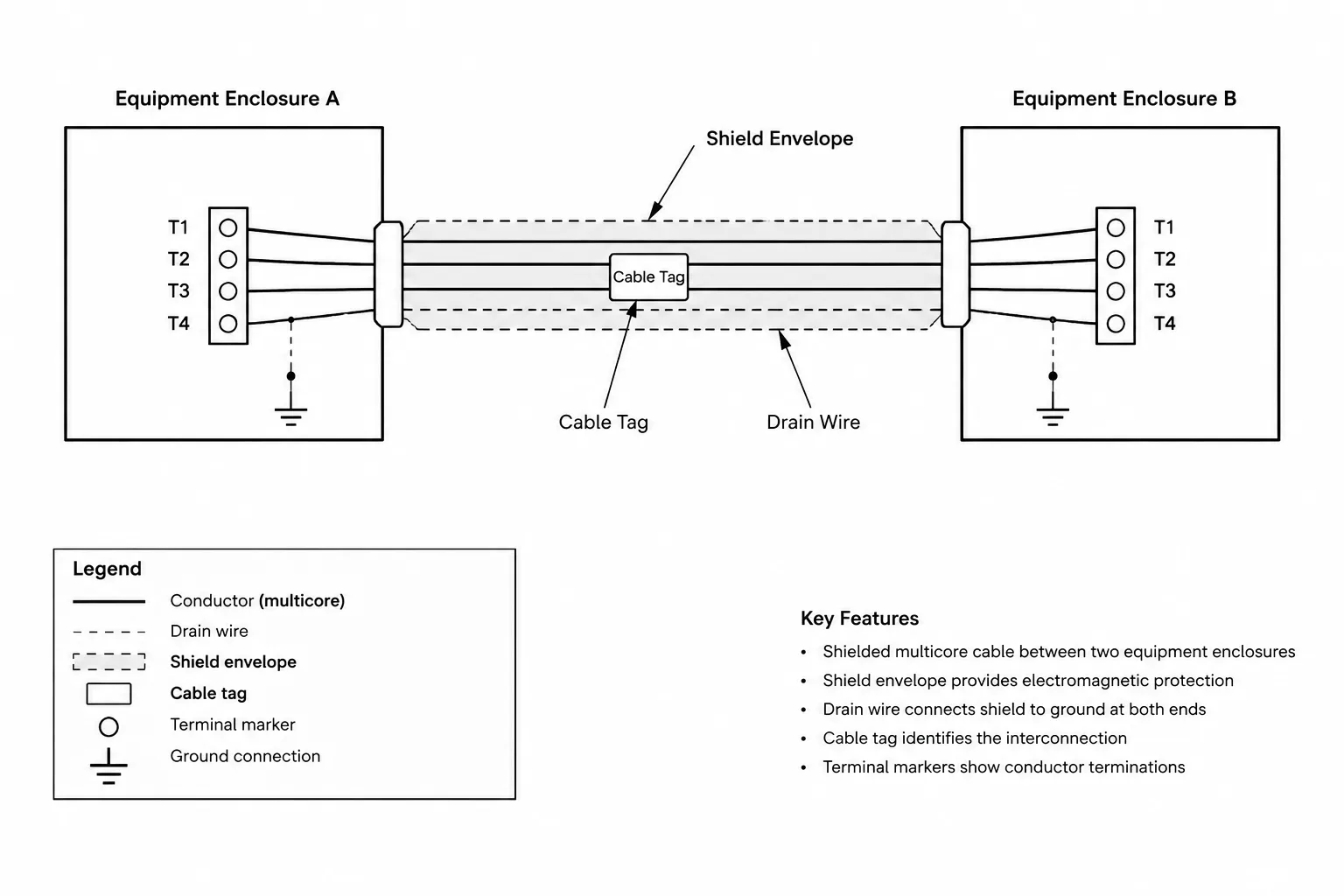
Line crossings should not carry the entire burden of explaining a complex connection. Use wire identifiers, cable tags, terminal designations, source-and-destination references, or continuation references where appropriate to the drawing type.
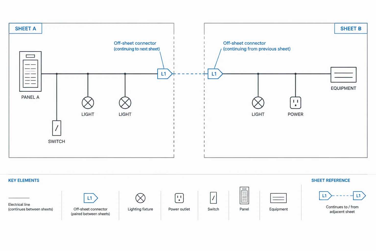
These identifiers provide a second way to verify connectivity. If a path is interrupted between sheets or drawing zones, a clear reference is usually more useful than forcing a continuous line through crowded graphics.
Differences Between Drawing Types
Crossing treatment should reflect the purpose of the drawing. In a schematic, each line may represent a specific electrical relationship, so junction clarity is critical. In a wiring or interconnection diagram, wire and terminal identifiers can help confirm whether paths actually join. In a single-line diagram, one drawn line may represent a broader circuit relationship, but branch points still need to be unmistakable.
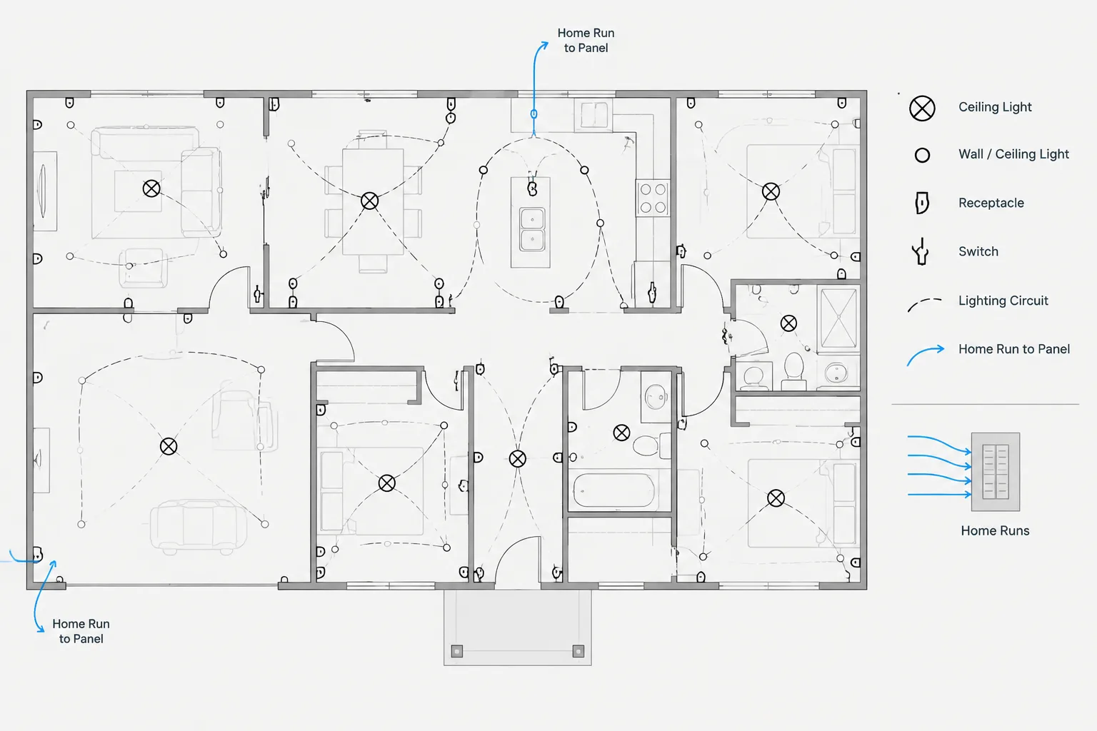
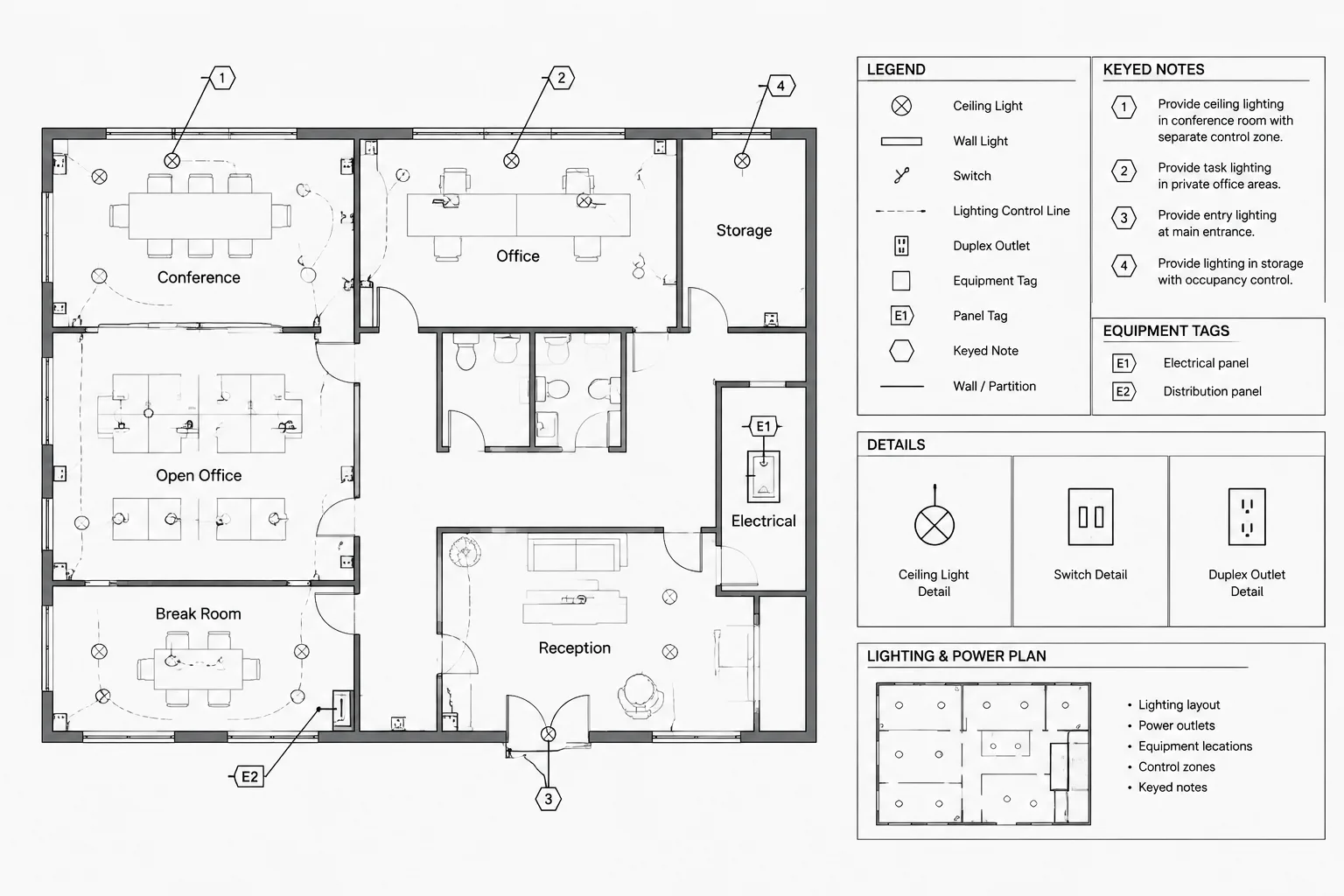
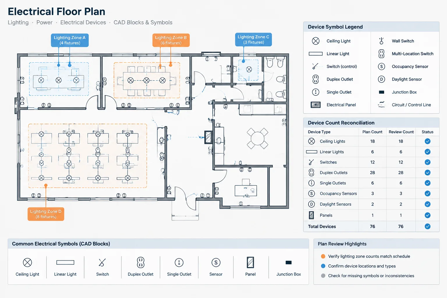
Plan drawings introduce a different issue. Circuit lines, home-run graphics, device links, and control indications may cross architectural walls or other electrical annotations without representing physical conductor intersections. The plan legend and line styles should distinguish symbolic circuiting from actual routed raceway when both appear in the same set.
Never transfer a crossing convention from one drawing type to another without considering its meaning. A visual method that is clear in a control schematic may be misleading on a floor plan.
Quality-Control Checks for Line Crossings
Perform crossing review at both editing scale and plotted sheet scale. Excessive zoom can conceal readability problems because tiny gaps and markers appear much larger on screen than they do in the issued drawing.
- Trace each major path from source to destination.
- Confirm that every intended branch visibly connects.
- Check that nonconnected crossings use the selected project convention.
- Search for endpoints that stop just short of another line.
- Look for duplicate or overlapping line segments.
- Verify that junction markers are centered and not duplicated.
- Review masks, wipeouts, and draw order with all applicable layers displayed.
- Check crossings near device symbols, terminal blocks, and continuation references.
- Plot or publish a test sheet to confirm that dots, gaps, and bridges remain distinct.
- Compare related sheets so the convention does not change between diagrams.
Keeping the Diagram Unambiguous
The best crossing is often the one that can be removed through better diagram layout. When a crossing is necessary, use a documented graphical treatment that remains clear in CAD, PDF, and printed output. Support the graphic with tags and references when the circuit relationship is complex.
Most importantly, treat crossings as electrical information rather than decorative linework. A small dot, gap, or bridge can change the interpreted meaning of a diagram. Consistent drafting and deliberate quality control help ensure that the drawing communicates the intended connection without requiring the reader to guess.
Audit Connectivity Separately From Graphic Appearance
A clean-looking diagram is not necessarily a correct diagram. During review, treat connectivity as a separate information layer and examine what each branch, endpoint, junction marker, bridge, and continuation reference means. This approach helps reveal errors that may be overlooked during a general visual check.
Where the CAD platform supports object data or intelligent connections, compare that information with the plotted representation. Where the file contains ordinary lines, polylines, arcs, or blocks, remember that apparent contact may have no built-in electrical meaning. The graphic must therefore communicate the relationship clearly on its own.
Trace paths in both directions
Following a path from its source toward its destination can reveal an unexpected interruption. Tracing the same path in reverse can expose a false branch or crossing that seemed natural when viewed in the original direction. Tags, terminal references, and continuation notes should agree with the visible route.
Review the deliverable, not only the model
Line crossings should be checked in the format that reviewers and field users will receive. Layer visibility, lineweight processing, raster conversion, background masks, and draw order can change how a junction or nonconnection appears. A successful on-screen inspection does not replace review of the published sheet.
Managing Crossings During File Handoffs
Imported details and vendor diagrams should be reviewed before they are incorporated into a larger drawing set. Their crossing convention may differ from the project convention even when the graphics look familiar. Preserve the verified electrical meaning while adapting presentation only when the required interpretation is understood.
For reusable blocks, keep junction and bridge graphics easy to identify and edit. Block names, layer assignments, insertion behavior, and plotted appearance should support consistent use. Avoid exploding controlled symbols unless the resulting linework will be checked and managed carefully.
Practical Review Principle
If a reviewer must pause to decide whether lines connect, the crossing deserves revision or supporting identification. Better routing may remove the conflict; otherwise, a clear marker, documented convention, or reference can make the intended relationship explicit.
Frequently Asked Questions
Does every connected crossing need a junction dot?
That depends on the documented project convention. A T-shaped branch or intersecting linework may indicate a connection in some drawing systems, but an explicit junction marker can reduce uncertainty. Apply the selected convention consistently and explain it in the legend when interpretation could vary.
Does a plain crossing always mean the lines are not connected?
No. The meaning of an unmarked crossing depends on the convention used by the drawing author. Check the legend, related sheets, path identifiers, terminal references, and surrounding circuit logic rather than assuming a universal meaning.
Should a bridge be created with an arc or a masking object?
Either approach may be part of a controlled CAD method, but each requires review. Arc-based graphics must remain aligned with the passing line, while masks can conceal nearby content or behave unexpectedly after draw-order changes. Use the method defined for the drawing set and verify its published appearance.
Why can a junction look correct in CAD but disappear in the output?
Plot processing, lineweight, scaling, rasterization, background graphics, and overlapping objects can reduce the visibility of a small marker. Review a published test output rather than relying only on a magnified model-space view.
How should a crossing from an imported vendor diagram be handled?
Determine the vendor diagram’s intended connectivity before changing its graphics. Compare identifiers, terminals, device relationships, and continuation references. Once the meaning is verified, document or adapt the convention in accordance with the project requirements.
Can wire tags compensate for an unclear crossing?
Tags and references provide valuable secondary confirmation, but they should not be used to excuse ambiguous linework. The path geometry and crossing convention should remain understandable, with identification supporting rather than replacing the graphic relationship.
Leave a Reply
You must be logged in to post a comment.