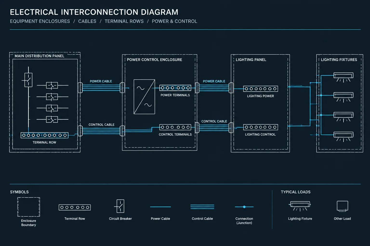
Electrical interconnection diagrams bridge the information gap between schematics, equipment drawings, cable schedules, and physical plans. In CAD, the main drafting challenge is not simply drawing connection lines; it is keeping every endpoint, terminal designation, cable identifier, and document reference coordinated as the design develops.
This guide explains how to organize electrical interconnection diagrams in CAD for readable plotting, efficient review, and controlled revision. It focuses on documentation practices rather than installation instructions, equipment ratings, or assumptions about field conditions.
An electrical interconnection diagram shows how separate equipment, panels, field devices, terminal assemblies, and cables connect across a system. Unlike a floor plan, it is usually not concerned with physical routing. Unlike an internal schematic, it does not need to explain every function inside a device. Its primary purpose is to document connection points clearly enough for design coordination, fabrication review, installation planning, testing, and record documentation.
A well-structured electrical interconnection diagram in CAD helps readers answer practical questions: Where does a cable originate? Where does it terminate? Which conductors are used? Does the connection pass through a terminal strip or junction box? Which drawing contains the internal circuit? The drafting methods below focus on organizing that information without implying unverified ratings, installation requirements, or project approval.
What an Interconnection Diagram Should Communicate
The diagram should identify the connected equipment and describe the path between connection points. Depending on the project, those points may include panel terminals, control cabinet terminals, motor connections, instruments, sensors, communication devices, packaged equipment, junction boxes, or field disconnects.
A useful interconnection diagram commonly communicates:
- Equipment or device tags
- Terminal designations
- Cable or wire identifiers
- Individual conductor or pair references
- Shield and drain-wire treatment where relevant
- Intermediate junction boxes or terminal strips
- Destination and source references
- References to schematics, plans, schedules, or equipment drawings
- Connection status, such as existing, new, future, or removed, when applicable
The drawing should show documented design intent rather than assumed field conditions. Connections supplied by a manufacturer or another discipline should be identified as such and checked against current project information.
Interconnection Diagram vs. Related Drawing Types
Several electrical documents may show the same device, but each presents a different view of it. Establishing the intended role of the interconnection diagram prevents it from becoming an overloaded hybrid.
| Drawing type | Primary purpose | Typical emphasis |
|---|---|---|
| Interconnection diagram | Shows connections between equipment or assemblies | Terminals, cables, conductors, and endpoints |
| Schematic diagram | Explains circuit function or control logic | Electrical relationships and operating sequence |
| Wiring diagram | Documents detailed wiring within or between assemblies | Wire-level connections and device pins |
| Single-line diagram | Summarizes power distribution | Sources, buses, feeders, protective devices, and loads |
| Floor or equipment plan | Shows physical location and general routing | Placement, spatial coordination, and plan references |
| Cable schedule | Lists cable information in a structured format | From/to data, service, conductor description, and remarks |
The interconnection diagram can reference all of these documents, but it should not duplicate their full content unless the project documentation strategy specifically requires it.
Plan the Diagram Structure Before Drawing
Choose a Consistent Reading Direction
Many interconnection diagrams read from source to destination, left to right. Others place control equipment on one side and field equipment on the other. Either approach can work if it is applied consistently throughout the drawing set.
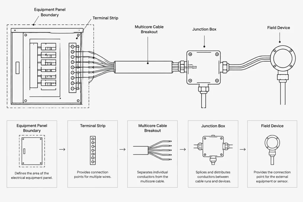
Do not change direction merely to fill empty sheet space. Reversals make cable paths and terminal sequences harder to follow. If a connection continues to another area or sheet, use an explicit continuation reference rather than an unexplained line ending.
Establish Equipment Boundaries
Represent each panel, cabinet, package, or field assembly with a clear boundary. Place the equipment tag and description in a repeatable location, such as at the top of the boundary. Internal items should be visually subordinate to the equipment identity.
Different boundary styles may distinguish physical enclosures, functional groups, and scope divisions, but the legend should explain the difference. Avoid using several nearly identical dashed linetypes without a clear meaning.
Separate Internal and External Connections
An equipment boundary should make it evident whether a terminal is inside the assembly or represents an external connection point. If internal wiring is outside the drawing scope, show only the interface terminals and provide a reference to the relevant schematic or vendor document.
This approach keeps the interconnection diagram focused and reduces the risk of copying internal details that may change during equipment selection.
Build Reusable CAD Components
Reusable blocks can improve consistency, but they should remain flexible enough to represent project-specific information. Useful block types include:
- Equipment boundary headers
- Terminal points and terminal-strip segments
- Plug and receptacle connectors
- Cable identification callouts
- Shield and drain-wire symbols
- Continuation arrows
- Drawing cross-reference markers
- Scope or responsibility notes
Attributes can store tags, terminal numbers, cable identifiers, and references. Attribute prompts should use the same terminology found in schedules and project databases. Avoid embedding assumed terminal values or fixed cable descriptions in a generic block.
Dynamic or adjustable symbols may be useful, but their plotted appearance should be tested. A block that stretches correctly on screen may still create crowded attributes, inconsistent line spacing, or ambiguous terminal alignment.
Draft Terminals and Conductors Clearly
Align Terminals in Logical Sequences
Place terminal points in an orderly row or column and preserve the sequence used by the source documentation. If a terminal designation contains letters, punctuation, or grouped identifiers, reproduce it consistently rather than simplifying it differently on separate sheets.
Spare terminals can be shown when they are relevant to the documented assembly, but they should not be confused with unassigned drawing space. Use an explicit label or schedule status where needed.
Keep Each Connection Traceable
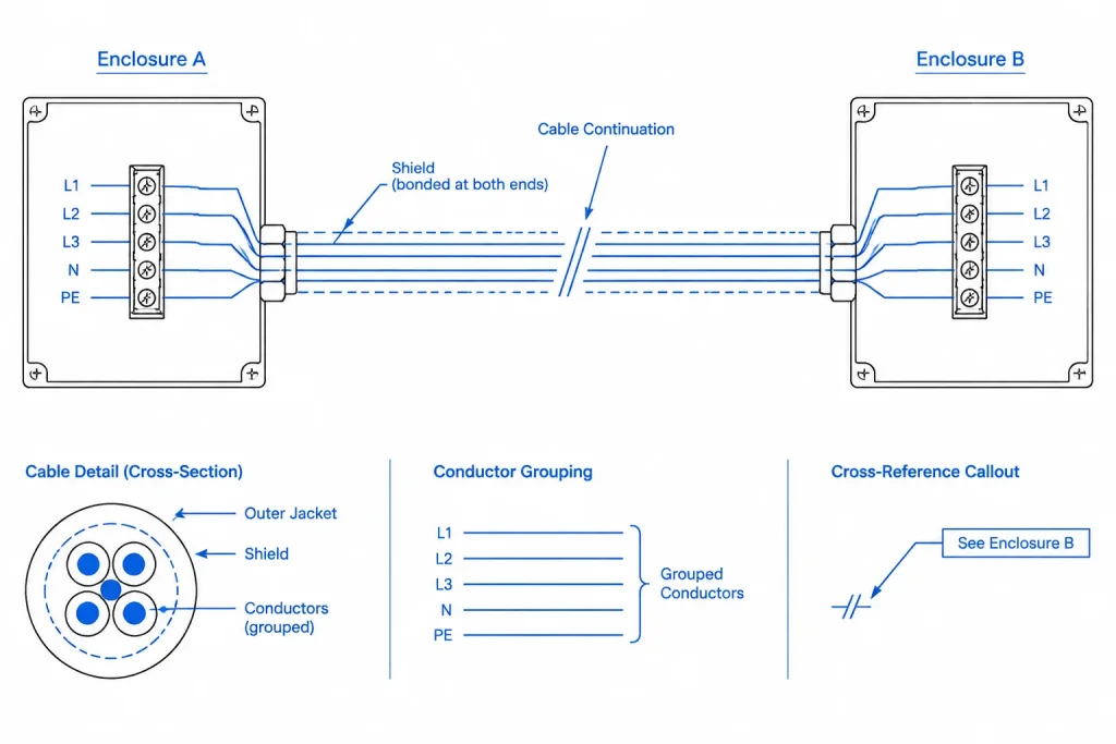
A reader should be able to follow a line from one identified endpoint to another. Where several conductors run together as one cable, show the cable grouping without hiding individual terminations. Where individual wires separate from a multicore cable, use a clear breakout arrangement.
Avoid long parallel lines with no intermediate labels. Repeating the cable identifier near both ends can improve traceability, particularly on large diagrams or when connections pass through multiple terminal assemblies.
Document Shields Without Ambiguity
Shielded cable graphics should distinguish the shield from the signal conductors. The diagram should also make clear where the shield, screen, or drain conductor is shown as connected, isolated, or continued. Do not infer this treatment from a generic symbol; it must be coordinated with the project design and equipment documentation.
Coordinate Cable and Terminal Data
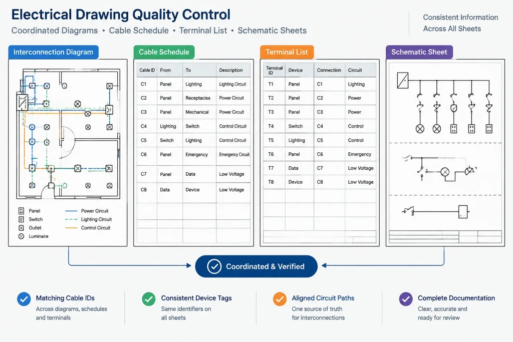
The same connection may appear in the interconnection diagram, cable schedule, terminal plan, equipment schematic, and field device list. Consistent identifiers allow those documents to support one another.
During drafting, compare at least the following data:
- Equipment tags at both cable endpoints
- Cable identifier and service description
- Terminal or connector designations
- Conductor, pair, or core identifiers
- Intermediate enclosure references
- Sheet and detail cross-references
- Connection status and project phase
If a cable schedule includes information that is not useful on the diagram, do not repeat it simply for completeness. Conversely, a diagram may need terminal-level detail that is too granular for the primary cable schedule. Define which document controls each type of information.
Use Layers to Support Editing and Review
A practical layer structure separates major graphic functions without creating unnecessary complexity. Typical categories may include equipment boundaries, terminals, conductors, cable callouts, text, cross-references, existing work, and revision graphics.
Use layer properties to create visual hierarchy. Equipment boundaries, connection lines, terminal graphics, and annotations should remain distinguishable when plotted in monochrome. Color alone should not carry essential meaning because colors may be altered by plot settings or lost in printed review sets.
Keep temporary markups and imported reference geometry away from issued drawing layers. If external equipment drawings are used as references, simplify or screen them so they do not compete with the actual connection information.
Manage Continuations Across Sheets
Large systems often require connections to continue between sheets. Every continuation should include enough information to locate its counterpart. Depending on the drawing convention, that may include a destination equipment tag, sheet reference, zone reference, or matching connection identifier.
Continuation symbols must be paired and reviewed in both directions. A source reference that points correctly to another sheet is incomplete if the destination does not point back or cannot be located easily.
Consider grouping sheets by system, source panel, equipment area, or connection function. Whichever method is chosen, explain it in the drawing index or general diagram notes.
Apply a Focused Quality-Control Review
Before issuing the drawing, review it as a connected information system rather than as a collection of lines and symbols.
- Confirm that every connection has identifiable endpoints.
- Check that equipment tags match plans, schedules, and related diagrams.
- Compare terminal designations with current equipment information.
- Look for duplicated cable identifiers or unexplained identifier changes.
- Verify that conductors do not appear connected merely because lines cross.
- Check all continuation and cross-reference pairs.
- Confirm that shield and drain-wire graphics are intentional.
- Review text collisions, boundary overlaps, and congested breakouts.
- Plot the sheets and assess readability at the intended output size.
- Flag unresolved vendor, field, or design information instead of guessing.
Automated attribute extraction can help identify missing tags or duplicate identifiers, but it cannot confirm design intent. Visual review and comparison with current project documents remain necessary.
Create a Diagram That Can Be Maintained
An effective electrical interconnection diagram is not only readable at issue time; it is structured for later revisions. Consistent blocks, predictable reading direction, disciplined tags, and coordinated references make changes easier to trace. They also reduce the chance that a cable schedule, terminal drawing, and schematic will drift apart.
Treat the diagram as an interface document between equipment and drawing types. Show enough detail to define each connection, but keep unrelated physical routing and internal circuitry in the documents designed to communicate those subjects. The result is a clearer CAD drawing that supports coordination without overstating what has been verified.
Define Information Ownership Before Issuing the Drawing
Interconnection data is often distributed across several project documents. Before completing the diagram, establish which document controls each information category. The equipment drawing may control connector designations, the cable schedule may control cable identifiers, and the schematic may control circuit relationships. The interconnection diagram should present coordinated data without creating an independent version that can drift from its source.
When information is incomplete, use the project’s approved notation for unresolved items. A visible coordination note is preferable to a plausible-looking terminal or conductor assignment that has not been verified.
Use a Change-Control Workflow
Revisions should be evaluated by connection rather than by graphic object alone. Moving a line or editing an attribute may affect endpoint data, terminal assignments, schedules, continuation references, and related sheets.
- Identify the documents affected by the revised connection.
- Compare both endpoints with the current equipment information.
- Update associated cable, conductor, and terminal references together.
- Review continuation markers on every affected sheet.
- Remove obsolete annotations that could be mistaken for active information.
- Confirm that revision graphics do not obscure terminal or cable labels.
Check the CAD File as a Deliverable
A diagram can appear correct on screen while remaining difficult to maintain or plot. The final CAD review should therefore address file structure as well as technical content.
- Confirm that reusable symbols follow the project’s block and attribute conventions.
- Look for exploded blocks, duplicate geometry, and disconnected attributes.
- Check that text styles, line properties, and annotation placement remain consistent.
- Verify that reference files are current and do not introduce unwanted layers.
- Test the plotted output in the intended presentation format.
- Confirm that searchable identifiers remain legible and are not replaced by indistinct graphics.
These checks help preserve the diagram as an editable project record rather than a drawing that is readable only in its current state.
Frequently Asked Questions
What is the main purpose of an electrical interconnection diagram?
It documents how separate equipment, panels, terminal assemblies, field devices, and cables connect. Its emphasis is on identifiable endpoints and connection data rather than physical cable routing or complete internal circuit operation.
Should an interconnection diagram show internal device wiring?
Only when that detail is part of the drawing’s defined scope. Otherwise, the diagram can show interface terminals and refer readers to the appropriate schematic or equipment document.
How should cable information be coordinated in CAD?
Use consistent identifiers for the cable, its endpoints, conductors, terminals, and intermediate enclosures. Compare those identifiers with the cable schedule and related drawings whenever a connection is added or revised.
Why are equipment boundaries important?
Boundaries clarify which terminals and components belong to each panel, cabinet, package, or field assembly. They also help distinguish internal items from external connection points and scope divisions.
Can CAD attributes be used for terminal and cable data?
Yes. Attributes can support consistent tags, terminal designations, cable identifiers, and cross-references. Their field names and terminology should match the project’s schedules and data-management conventions.
How should incomplete connection information be handled?
Do not guess. Mark the item using the project’s approved pending or coordination notation, identify the responsible information source, and update the connection after verified documentation becomes available.












Leave a Reply
You must be logged in to post a comment.