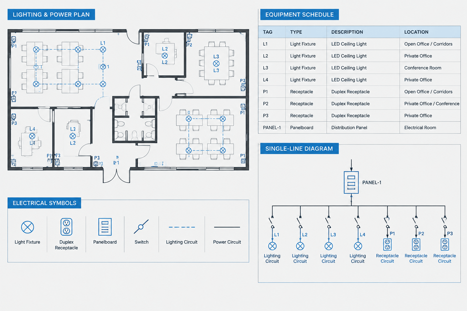
Electrical device tagging in CAD connects symbols on a plan to the schedules, diagrams, details, and specifications that explain them. A clear identifier helps a reader recognize that an item shown in one view is the same item referenced elsewhere in the drawing set. An inconsistent identifier can create duplicate equipment records, broken schedule references, and uncertainty during coordination.
Tagging is not simply a matter of placing text beside a CAD block. It is a documentation system. The drafter must decide which information belongs in the visible tag, which information belongs in a schedule, and which drawing or data source controls each field. The following workflow focuses on creating readable and maintainable identifiers without treating a block label as a substitute for engineering verification.
What an electrical device tag represents
A device tag is a concise identifier assigned to an electrical item or coordinated equipment connection. Depending on the project, tagged items may include switchboards, panelboards, transformers, disconnects, generators, transfer equipment, motor controllers, lighting control devices, junction boxes, receptacle assemblies, and equipment served by electrical systems.
The tag usually performs one or more of these functions:
- Distinguishes one item from other similar items.
- Connects a plan symbol to a schedule row.
- Provides a reference shared by electrical and other disciplines.
- Links an equipment location to a single-line or riser diagram.
- Supports drawing review, revision tracking, and field coordination.
A tag should identify an item, not attempt to describe every technical characteristic beside the symbol. Ratings, feeder information, circuit assignments, mounting requirements, and other properties often belong in schedules, diagrams, specifications, or notes. The appropriate division of information depends on the project documentation standard.
Build a tag structure before placing blocks
Before tagging a plan, define a repeatable identifier structure. A typical structure may use a category abbreviation followed by a unique sequence or location-based suffix. Some projects also include system, building, floor, or service-area information. There is no universal format suitable for every drawing set, so the project naming convention must be confirmed before widespread use.
Keep identifiers concise
A long identifier may encode useful information, but it also consumes plan space and becomes difficult to read in dense rooms. Use only the components needed to distinguish and coordinate the item. Information that changes frequently should be kept out of the identifier when possible. For example, embedding a room name in every tag can create extensive renaming work if architectural room names change.
Avoid overloaded abbreviations
An abbreviation should have one intended meaning within the drawing set. If the same letters represent both an equipment type and a system designation, readers may interpret tags differently. The electrical legend, equipment schedule, and project abbreviation list should use matching terminology.
Separate identity from technical data
The item identifier should remain distinguishable from circuit numbers, panel references, electrical characteristics, and status notes. A reader should be able to tell whether adjacent text is the permanent equipment tag or a property that may change during design.
Establish a source of truth for each field
Coordination becomes more reliable when every piece of information has an identified controlling source. If the same property is manually entered in several places, one occurrence will eventually become outdated.
| Information | Possible controlling source | Coordination concern |
|---|---|---|
| Device or equipment identifier | Electrical equipment register or coordinated project list | Prevent duplicate or retired tags from remaining on plans |
| Plan location | Coordinated floor plan or equipment layout | Track architectural and mechanical layout changes |
| Panel and circuit reference | Panel schedule and circuiting documentation | Avoid copying outdated circuit data into static text |
| Feeder relationship | Single-line or riser diagram | Confirm that upstream and downstream identifiers agree |
| Equipment description | Equipment schedule or design register | Use consistent terminology across disciplines |
| Installation note or detail reference | Plan note, detail callout, or specification reference | Do not embed temporary instructions in the permanent tag |
The selected sources will vary by project. The important drafting principle is to document the hierarchy and avoid allowing several drawings to appear equally authoritative when they contain conflicting information.
Create tag-ready CAD blocks
A reusable symbol should provide a predictable location for identification. Where the CAD platform and office workflow allow it, block attributes or equivalent object data can hold the visible tag and related properties. This reduces detached text and makes it easier to extract or audit records.
A practical tag-ready block may include:
- A clear symbol origin and insertion point.
- A dedicated identifier field.
- Optional fields for circuit, panel, system, or description data.
- Consistent text style, height, orientation, and justification.
- Visibility choices for plan, enlarged plan, or diagram use where supported.
- A defined layer assignment for symbols and annotations.
Do not assume that downloaded blocks already follow the project convention. Inspect their units, layers, attributes, text styles, geometry, and plotting behavior before adding them to the office library. A generic symbol may be useful as a starting point, but its tag fields and meaning still require project-specific verification.
Coordinate tags across drawing types
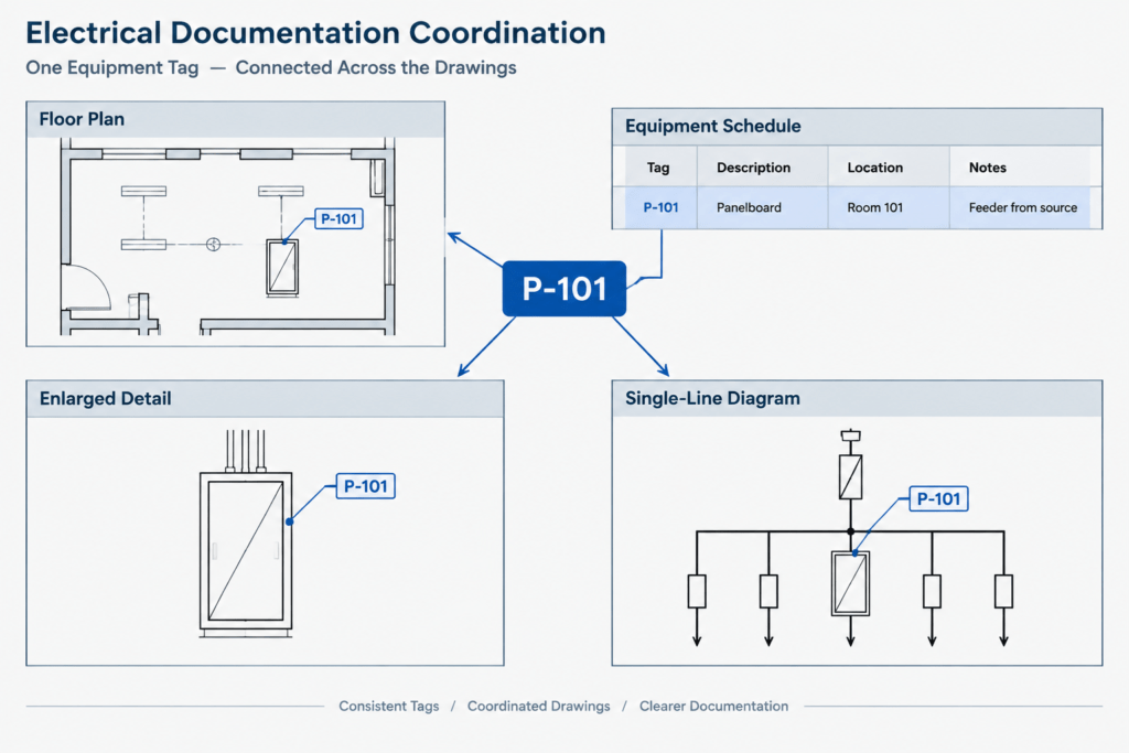
Floor plans
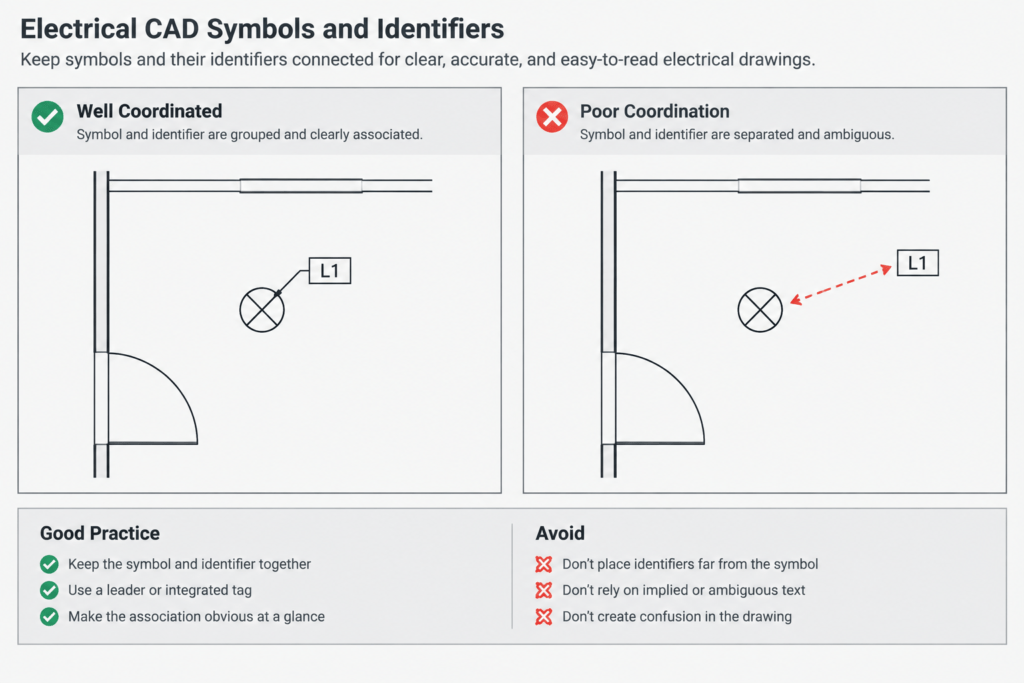
On floor plans, place the identifier close enough to the symbol that ownership is obvious. Use a leader when several devices are clustered or when placing text beside the symbol would cause ambiguity. Keep the tag readable over the architectural background, but avoid masking doors, walls, dimensions, and room information needed for coordination.
Equipment schedules
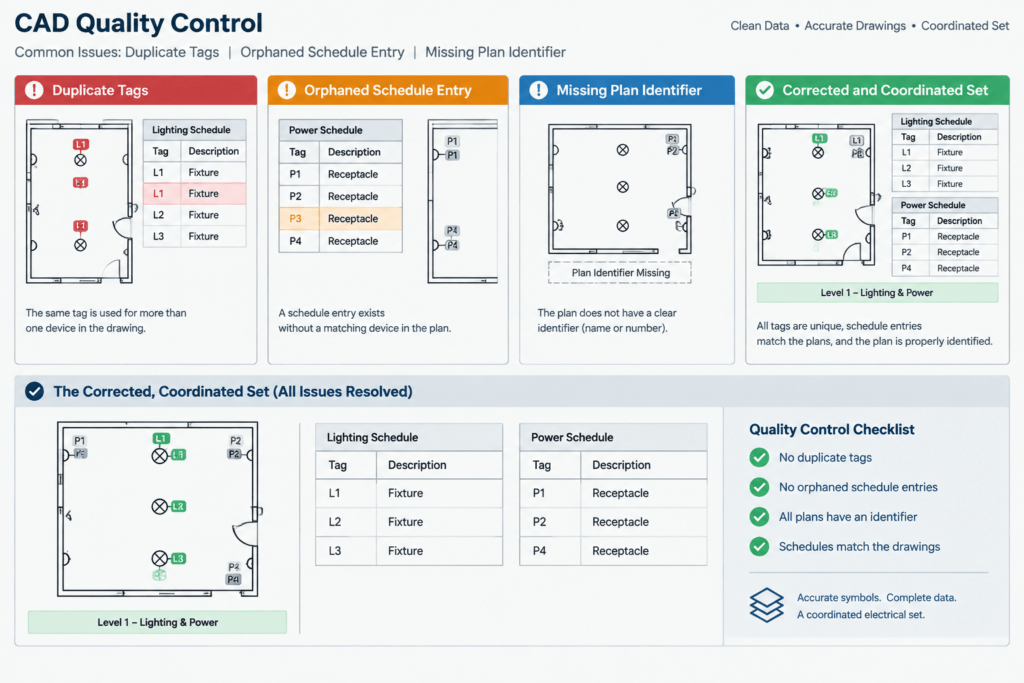
Every scheduled identifier should have a corresponding intended item, and every tagged scheduled item should appear in the correct schedule. Watch for blank schedule rows, duplicate identifiers, and symbols that were copied without updating their attributes. If one schedule row represents several identical items, make that grouping method explicit rather than implying that a single identifier belongs to multiple independent devices.
Single-line and riser diagrams
Use the same identifiers shown on the plans unless the project deliberately uses a documented diagram-specific convention. Diagram tags should clarify system relationships, while plan tags clarify physical location. A mismatch between these views can make it appear that equipment is missing or connected differently.
Details and enlarged plans
An enlarged plan should not create a second identity for the same object. If the parent plan uses a simplified symbol and the enlargement uses a detailed block, both should carry the same identifier. Use view references and detail callouts to connect the drawings rather than inventing another tag.
Other discipline drawings
Mechanical, plumbing, architectural, security, and controls drawings may refer to electrically served equipment. Agree on the shared identifier before final documentation. The electrical drawing can then associate its connection information with the equipment identity without renaming the other discipline’s asset unnecessarily.
Manage copied, moved, and deleted devices
Copying blocks is a common source of duplicate tags. A copied symbol may look correct while retaining the identifier and schedule properties of the original. Establish a routine that treats copied tagged equipment as incomplete until its identity has been reviewed.
Moving an item presents a different risk. The tag may remain valid, but room, area, circuiting, routing, or detail references may no longer apply. Deleting a symbol can also leave behind an orphaned schedule row, diagram node, keynote, or leader.
During revisions, review each changed item as a record rather than only as graphics:
- Was the identifier retained intentionally?
- Does the schedule still describe the item correctly?
- Does the diagram show the correct relationship?
- Are leaders and callouts attached to the intended symbol?
- Has a deleted item been removed from associated lists?
- Does the revision affect another discipline’s equipment register?
Run a tag coordination check
A tag audit can be performed with drawing data extraction tools, project databases, spreadsheets, or a structured manual review. The method matters less than comparing the same categories consistently.
At minimum, check for:
- Duplicate identifiers assigned to different items.
- Plan tags that do not appear in the relevant schedule.
- Schedule identifiers with no corresponding plan or diagram item.
- Different spellings, separators, or capitalization for the same equipment.
- Tags hidden by background graphics or annotation.
- Detached text that resembles a tag but is not linked to the block.
- Old identifiers remaining in details, notes, or diagrams after a revision.
- Placeholder tags that were never finalized.
Review plotted sheets as well as the model environment. A tag can be correctly entered but unreadable because of viewport scale, annotation settings, linework overlap, or plotting hierarchy.
Use tags as navigation, not as design approval
A coordinated identifier helps readers navigate the drawing set, but it does not confirm that equipment selection, circuiting, ratings, clearances, or installation requirements are correct. Those decisions require review against the project criteria, applicable requirements, manufacturer information, and responsible design documentation.
The most effective electrical tagging workflow keeps identifiers stable, assigns a controlling source to each property, and makes changes traceable across every related view. When CAD blocks, schedules, plans, and diagrams use the same documented identity, the drawing set becomes easier to review and substantially less vulnerable to coordination errors.


Leave a Reply
You must be logged in to post a comment.