
Motor and VFD drawings in CAD must communicate the same equipment relationship across several document types without duplicating unnecessary information. The drafting objective is traceability: a reviewer should be able to identify the motor, locate its drive, follow its electrical source, find its control interfaces, and recognize the associated mechanical or process equipment.
This reference explains how to coordinate those connected views while keeping each sheet appropriate to its purpose. It focuses on equipment tags, block attributes, drawing ownership, cross-references, graphic separation, and review practices rather than project-specific electrical design.
Motor and variable frequency drive documentation often spans several disciplines and drawing types. A motor may appear as a small symbol on a power plan, a connected load on a single-line diagram, a row in an equipment schedule, and a controlled device on a schematic. The variable frequency drive, or VFD, may be located beside the motor, mounted remotely, supplied as part of another assembly, or represented only through an interface diagram.
The drafting challenge is not simply drawing each component. It is maintaining a clear relationship among the motor, drive, disconnecting device, source, controlled equipment, and control system. A coordinated CAD workflow makes those relationships traceable without forcing every sheet to repeat the same information.
Start with the equipment relationship
Before placing blocks, define the functional chain shown by the project documents. A typical relationship may include a source, protective or switching equipment, a VFD, a motor, and the mechanical equipment driven by that motor. The actual arrangement must come from verified design information, vendor documents, and discipline coordination.
Create a simple equipment relationship list before drafting:
- Motor identifier
- Associated mechanical or process equipment identifier
- VFD identifier, when applicable
- Electrical source reference
- Local or remote equipment location
- Control-system interface
- Relevant schedule, diagram, or detail references
This list does not replace calculations or equipment data. It provides a documentation map that helps prevent disconnected tags and conflicting references.
Choose the right representation for each drawing
A motor and its drive should not look identical on every sheet. Each drawing type has a different communication purpose.
| Drawing type | Primary purpose | Typical motor or VFD information |
|---|---|---|
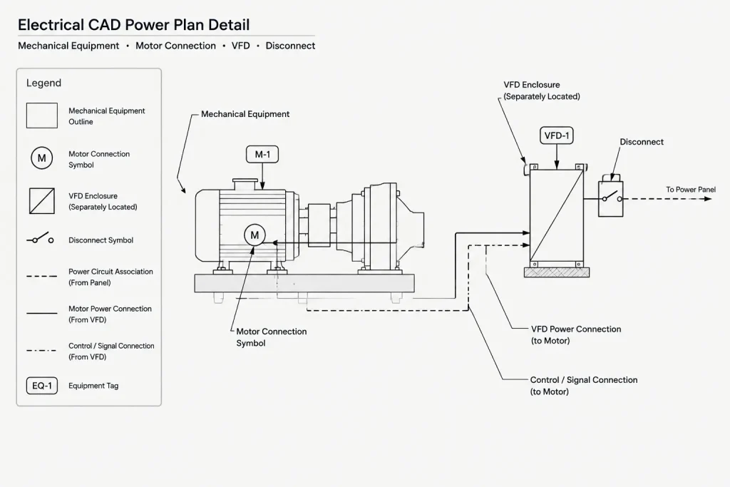
| Power plan | Show physical location and circuiting intent | Equipment symbol, tag, connection point, circuit reference, and nearby disconnect or drive location |
| Single-line diagram | Show the electrical distribution relationship | Source, feeder path, switching or protective devices, VFD, motor, and equipment identifiers |
| Control schematic | Explain operating logic and interfaces | Commands, status signals, permissives, interlocks, and references to other control documents |
| Equipment layout | Coordinate physical arrangement | Drive enclosure footprint, access area, adjacent equipment, and routing approach |
| Schedule | Organize repeated project data | Tags, service description, source, location, status, and drawing references |
| Connection or interconnection diagram | Clarify terminal-level or system-level relationships | From-to connections, cable identifiers, terminal references, and interface ownership |
A power plan usually needs a compact, readable symbol rather than internal drive detail. Conversely, a control drawing may require signal relationships that would clutter a floor plan. Use cross-references to connect these views instead of overloading one representation.
Build a consistent tag structure
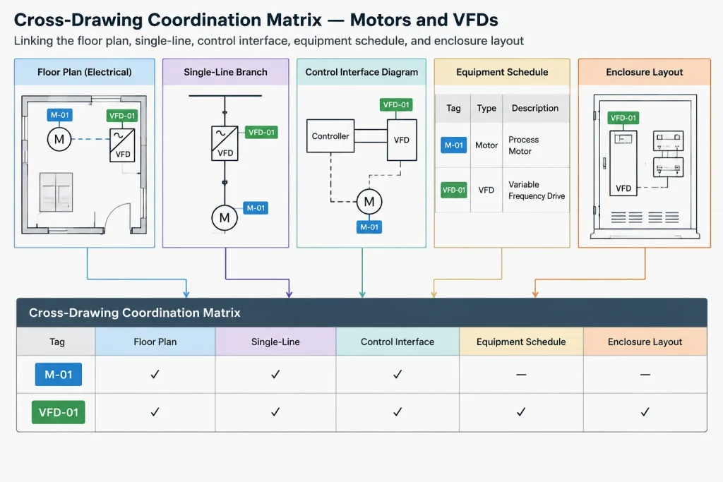
Consistent equipment identification is the main link between drawings. The same motor should not receive unrelated identifiers on the power plan, single-line diagram, and control schematic unless the project intentionally uses separate discipline tags and provides a cross-reference.
Where mechanical or process equipment already has an established identifier, coordinate the electrical motor and VFD tags with it. A drafting convention might distinguish the driven equipment, motor, and drive while preserving a shared relationship. The exact syntax should follow the project naming rules rather than a universal assumption.
Use attributes carefully
Motor and VFD CAD blocks can use attributes for information that benefits from structured editing and extraction. Useful fields may include the equipment tag, service description, source reference, and schedule key. Avoid placing every known equipment characteristic inside the plan symbol. Excessive attributes make blocks difficult to read and increase the chance that duplicated data will become inconsistent.
Decide which document owns each field. For example, the plan may own location, while a schedule owns descriptive data and the single-line diagram owns the distribution relationship. Other drawings should reference that information rather than independently restating it whenever possible.
Draft the power plan for location and connection intent
On the power plan, place the motor symbol or equipment connection marker at the coordinated connection location—not merely at the center of the mechanical equipment outline. If the exact connection point is unknown, use a clear preliminary convention and flag it for coordination rather than presenting an assumed location as final.
Show the VFD as a separate physical item when its location matters to installation or coordination. If the drive is integral to packaged equipment, identify that relationship so it is not mistaken for a separately located enclosure. If the drive is shown in another room or equipment area, use a tag and drawing reference to connect it to the served motor.
Keep circuiting lines readable around equipment footprints. The linework should communicate association without implying a precise conduit path unless the drawing is intended to document routing. Where several motors are grouped closely, leaders or keyed references may be clearer than overlapping circuit lines.
Show the distribution path on the single-line diagram
The single-line diagram should make the source-to-load relationship understandable. Arrange the motor branch so readers can follow the path through the relevant distribution and control equipment. Maintain the same motor and VFD identifiers used on the plans.
Avoid drawing the VFD as a generic box with no label. Even when detailed internal functions are outside the drawing scope, its identity and relationship to the motor should be unmistakable. Similarly, do not imply that every motor has the same arrangement. Bypass equipment, packaged starters, combination assemblies, and other configurations should only be shown when supported by project information.
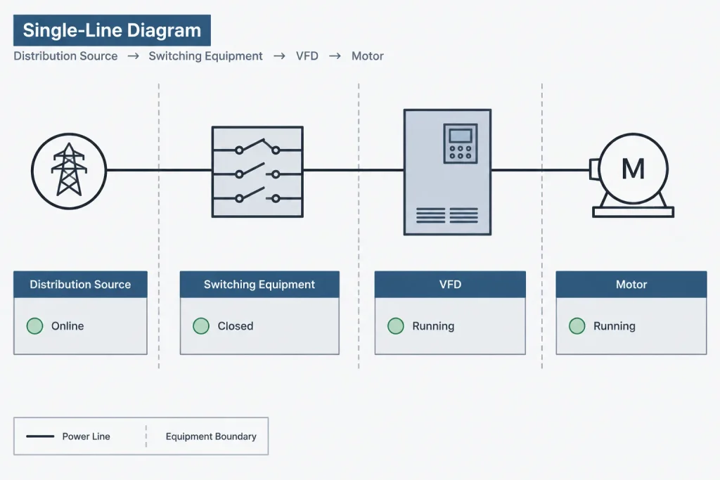
Use status notation consistently. Existing, new, relocated, future, or removed equipment should follow the project-wide graphic and text conventions. A status difference shown on the plan but omitted from the single-line diagram can create a significant documentation conflict.
Separate power conductors from control interfaces
Power and control information may share equipment tags, but they should remain graphically distinct. Use the project layer, linetype, and annotation conventions to differentiate power connections, hardwired control signals, network or communications relationships, and reference-only lines.
A control interface diagram can identify relationships such as:
- Start and stop commands
- Speed or process references
- Running, stopped, or fault status
- Safety or process permissives
- Local and remote control relationships
- Building automation or process-control interfaces
These are documentation categories, not a recommendation that every project needs each signal. Confirm required interfaces with the controls narrative, sequence of operations, approved equipment information, and responsible disciplines.
Coordinate enclosure layouts and routing space
When a VFD is shown on an electrical room or equipment layout, use a verified enclosure footprint or a clearly identified placeholder. Do not treat a generic CAD block as a confirmed product outline. The layout may also need to communicate door swing, access area, wall relationship, nearby equipment, and likely conduit or cable entry direction.
Keep clearance and service zones on dedicated layers so they can be reviewed without becoming permanent visual clutter on every plotted plan. Their geometry and meaning must come from applicable project criteria and verified equipment information.
Routing coordination should consider that power conductors, motor output connections, controls, and communications may have different documentation needs. The drawing should not collapse all connections into one ambiguous line if separate pathways or interfaces are important to coordination.
Use schedules without creating a second source of truth
A motor or VFD schedule can be useful when many similar devices appear in a project. However, schedules become unreliable when they duplicate fields already maintained elsewhere without a defined update process.
Assign ownership for recurring information. If the electrical equipment schedule controls source references, do not manually enter conflicting source text in several plan notes. If a mechanical schedule controls the equipment service description, preserve its equipment identifier and coordinate changes through a review process.
Schedule columns should serve a real documentation purpose. Possible fields include equipment tag, served equipment, plan location, source reference, control drawing reference, supplied-by notation, and remarks. Include only fields supported by project data.
Apply a cross-drawing review workflow
Before issuing the drawing set, review each motor and VFD as a connected record rather than checking sheets independently.
- Locate the motor or driven equipment on the plan.
- Confirm that its identifier matches the equipment schedule or coordinated discipline tag.
- Trace its source on the single-line diagram.
- Verify that a separately located VFD appears on the appropriate layout.
- Check control and interconnection references where those drawings are in scope.
- Compare equipment status across all views.
- Review notes for scope ownership, packaged equipment, and vendor-provided components.
- Confirm that detail and sheet references point to current drawing locations.
A simple review table can track the motor tag, plan sheet, diagram sheet, control reference, schedule row, and open coordination item. This is especially valuable when equipment identifiers change during design.
Common drafting problems to catch
- Orphaned motor symbols: A motor appears on the plan but has no identifiable source or diagram reference.
- Duplicate VFD tags: Copied blocks retain an identifier belonging to another drive.
- Conflicting locations: The plan shows a remote drive while the layout or schedule describes it as integral.
- Unverified footprints: Generic blocks are presented as exact enclosure outlines.
- Mixed line meanings: Power, control, and communications connections use indistinguishable graphics.
- Broken equipment relationships: Mechanical equipment is renamed, but associated motor and drive references are not updated.
- Excessive plan data: Detailed control notes make the floor plan unreadable while still failing to explain the full sequence.
A coordinated drawing set is more useful than a detailed symbol
The quality of motor and VFD documentation depends less on symbol complexity than on reliable relationships. A simple block with a consistent tag, verified location, clear source reference, and coordinated control link is more useful than a highly detailed symbol that conflicts with other drawings.
Treat the plan, single-line diagram, schedule, control drawing, and equipment layout as connected views of the same equipment record. Define which view owns each type of information, use cross-references deliberately, and verify generic CAD content against project-specific data before issue.
CAD implementation notes for coordinated motor and VFD records
A reliable workflow begins with a reusable equipment record rather than a collection of unrelated symbols. Define the approved identifier and the references that connect the motor, VFD, source, controlled equipment, schedule, and control documentation. Each drawing can then display the fields relevant to its purpose.
Separate symbol graphics from project data
Keep the visible block geometry simple and place editable project information in controlled attributes or associated schedules. This allows the symbol to remain legible while identifiers and references can be checked systematically. Avoid embedding assumptions about enclosure configuration, connection location, or internal drive functions in a generic block.
Use layers according to drawing meaning
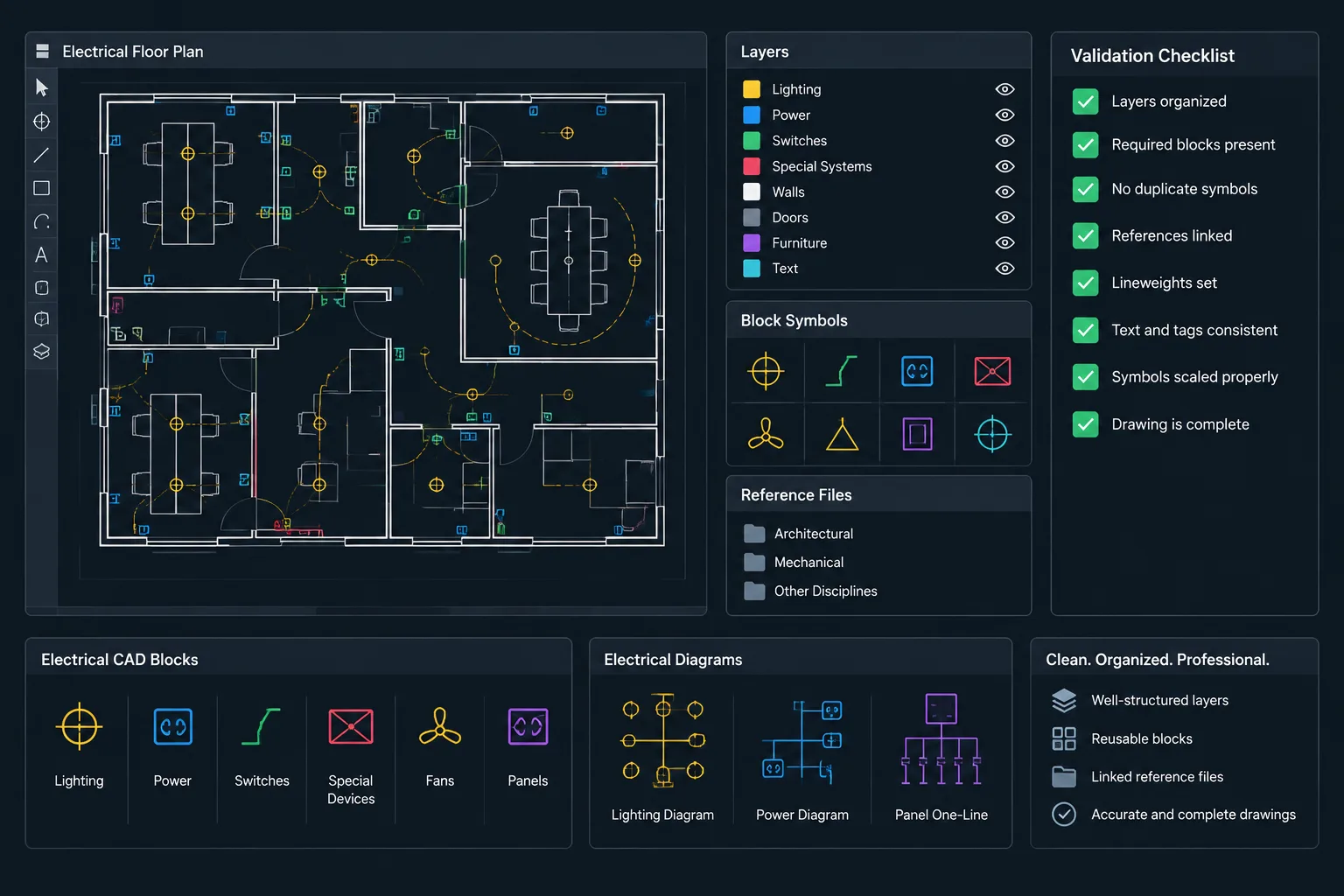
Layer organization should help distinguish equipment symbols, power relationships, control interfaces, communications references, annotations, access zones, and background information. Layer names and plotted appearance should follow the established project standard. The important drafting principle is that different line meanings remain recognizable during editing, review, and plotting.
Plan for revisions and substitutions
Equipment changes can affect plans, diagrams, schedules, layouts, and control references at the same time. When a motor or drive identifier changes, search the full drawing set for its former tag and review related attributes, leaders, notes, and schedule entries. A block replacement alone may not update text stored outside that block.
Perform a visual and data review
- Visual review: Check symbol placement, leader clarity, line crossings, text overlap, equipment status, and plotted readability.
- Relationship review: Confirm that the motor, VFD, source, driven equipment, and control system remain connected by consistent references.
- Data review: Compare block attributes and schedule fields for missing, duplicated, or outdated identifiers.
- Reference review: Verify that sheet, detail, schematic, and schedule references still point to the intended locations.
- Coordination review: Flag generic footprints, preliminary connection points, and unresolved interface ownership for project verification.
These checks improve documentation consistency, but they do not replace engineering review, approved equipment information, or discipline coordination.
Frequently asked questions
Should a motor and VFD use the same CAD block on every drawing?
No. The representation should match the drawing purpose. A plan may use a compact location symbol, while a single-line diagram shows the distribution relationship and a control schematic shows commands, status, permissives, and interlocks. Consistent identifiers and cross-references connect the different representations.
What information belongs in motor and VFD block attributes?
Attributes are most useful for structured fields such as equipment tags, service descriptions, source references, and schedule keys. Include only information that has a defined owner and update process. Detailed data that cannot be read clearly or maintained reliably is usually better placed in a coordinated schedule or reference document.
How should a remotely located VFD be shown?
Show the drive at its coordinated physical location on the applicable layout or plan, then connect it to the served motor through consistent tags and drawing references. Do not imply that the drive is adjacent to the motor when project information indicates otherwise.
Can a generic VFD CAD block represent the final enclosure?
A generic block can serve as a symbolic or preliminary placeholder, but it should not be treated as a verified product outline. Final layout geometry must be checked against approved equipment information and project criteria.
How can drafters prevent conflicting motor information across sheets?
Assign ownership for recurring data, use coordinated equipment identifiers, limit unnecessary duplication, and review each motor as a connected record across plans, diagrams, schedules, layouts, and control documents.
Should power and control connections use the same line style?
They should remain graphically distinguishable according to the project CAD standard. Clear layer, linetype, and annotation conventions help prevent power paths, hardwired controls, communications relationships, and reference lines from being misread.

Leave a Reply
You must be logged in to post a comment.