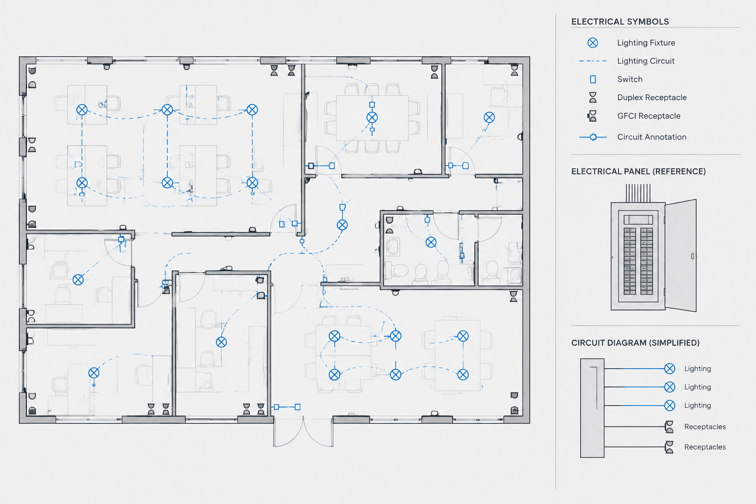
An architectural background is a live project dependency, not simply muted linework beneath an electrical plan. Its file path, coordinate basis, reference behavior, layer visibility, and revision status can all affect the accuracy and readability of electrical documentation.
This guide presents a practical electrical CAD xref workflow for receiving, reviewing, displaying, updating, and issuing referenced backgrounds. Apply it alongside the project’s established CAD standards, consultant exchange requirements, and document-control procedures.
External references allow an electrical drawing to display architectural, structural, mechanical, and other discipline files without permanently copying all of that geometry into the electrical model. Used well, references keep plans coordinated and make background updates easier to manage. Used carelessly, they can produce shifted devices, missing files, duplicated geometry, unreadable plots, and uncertain revision history.
A reliable electrical CAD xref workflow is therefore more than attaching a floor plan. It establishes how backgrounds are received, checked, positioned, displayed, updated, and packaged for issue. The goal is to preserve coordination while keeping the electrical drawing legible and under the electrical team’s control.
What an xref contributes to an electrical plan
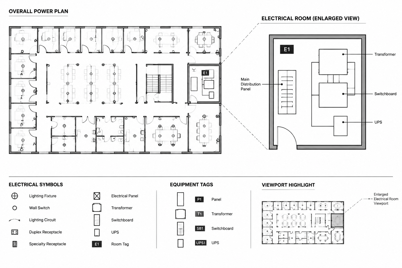
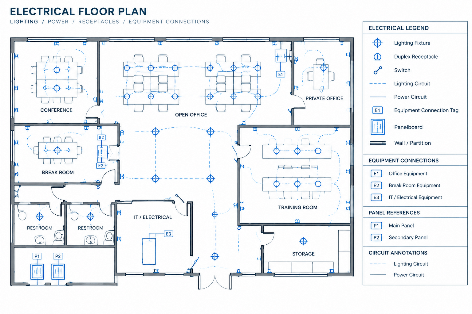
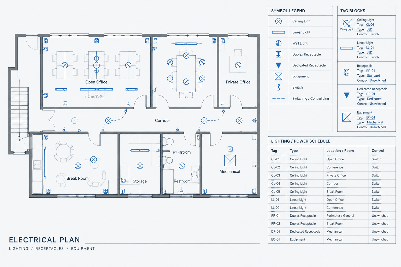
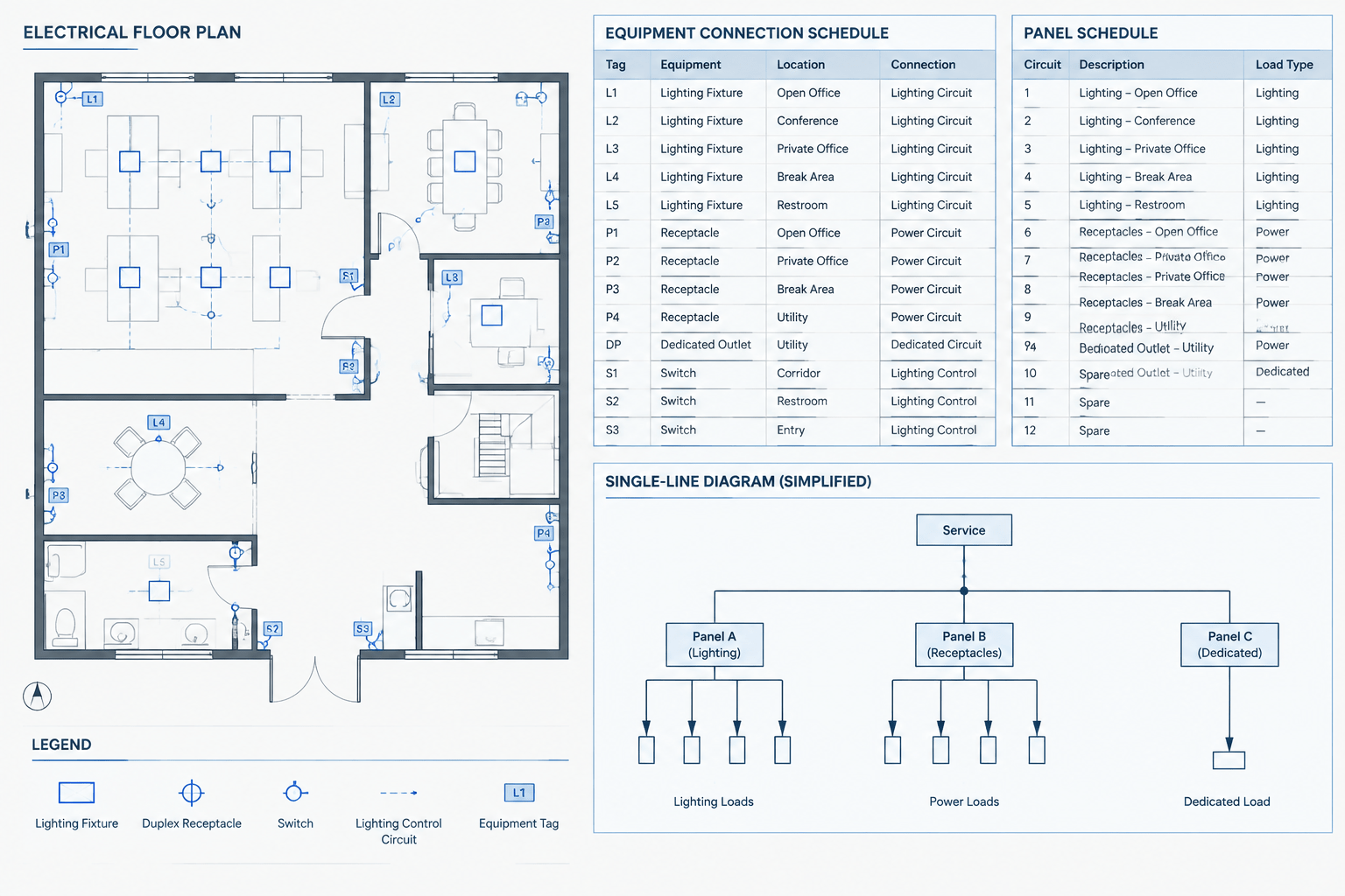
An architectural background commonly provides walls, doors, room names, ceilings, casework, equipment footprints, and other spatial information. Electrical content is then drawn in relation to that background. Depending on the sheet, the electrical file may add lighting fixtures, receptacles, equipment connections, pathways, circuit annotations, or control symbols.
The reference is not merely visual context. It is part of the coordination framework. If the background moves, an electrical device that was correctly placed beside a door or above a countertop may no longer align with the design. That is why background replacement should be treated as a controlled drawing update rather than a routine file swap.
Build a predictable file structure first
Reference stability begins with file organization. A project should have an agreed location for current backgrounds, electrical working files, plotted output, archived exchanges, and other supporting documents. The exact folder names matter less than consistent use.
Keep superseded consultant files separate from the active reference location. If old and current backgrounds share one folder with similar names, a drafter can easily attach the wrong file. An exchange log or simple transmittal record can identify the source discipline, date received, intended area, and whether the file has been accepted for coordination.
Relative reference paths are often more portable when an entire project directory is moved or transferred while preserving its internal folder structure. Full paths may be useful in controlled network environments but can fail when another user lacks the same drive mapping. The project team should choose one path strategy and test it before production work expands.
Inspect an incoming background before attaching it
Do not assume that every received file is ready to become a production reference. Open or review it separately before connecting it to the electrical drawing.
- Confirm that it represents the correct building, floor, area, and revision.
- Check the drawing units and insertion behavior.
- Look for unexpectedly distant objects that could distort drawing extents.
- Review whether model geometry is located at the project’s agreed origin or coordinate basis.
- Identify nested references and determine whether the required supporting files were included.
- Check whether room names, reflected ceiling information, equipment, and other expected coordination content are present.
- Note duplicate geometry, unexplained rotations, or separate options shown in the same file.
This review does not authorize the electrical drafter to redesign or broadly clean another discipline’s file. It identifies issues that need to be resolved before the background becomes the basis for electrical documentation.
Use a shared coordinate strategy
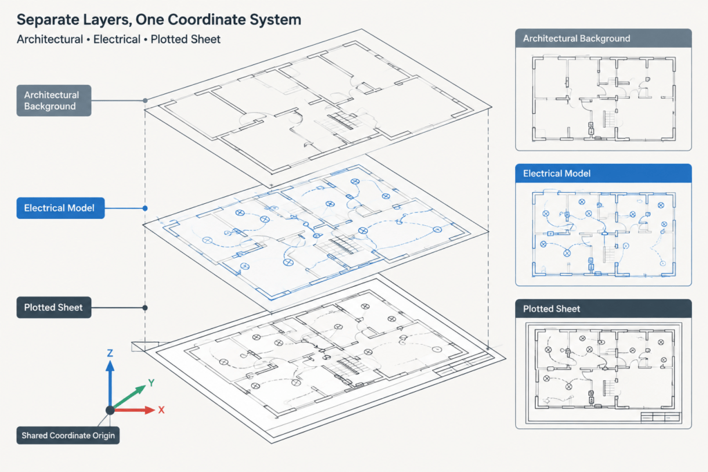
The most important rule is simple: establish a common project position and avoid correcting alignment by eye. Insertion point, scale, and rotation should follow the project’s documented coordinate method.
Manual nudging can appear successful on one sheet while causing errors elsewhere. It also makes future replacement difficult because a new version may attach at its true project position rather than the improvised position of the previous file. If a background arrives out of alignment, document the condition and coordinate a correction instead of hiding the problem with an unrecorded move.
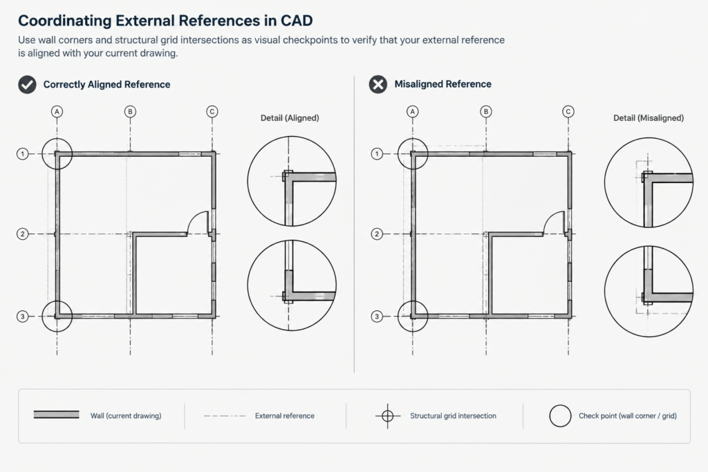
After attachment, verify alignment at several separated locations. Grid intersections, major wall corners, cores, or other stable building features are better checks than a single doorway. A reference that aligns at one point but diverges elsewhere may have a scale, rotation, unit, or source-coordinate problem.
Choose attachment or overlay intentionally
Many CAD systems distinguish between attachment-style and overlay-style references. An attached reference can be carried forward when its host file is referenced into another drawing. An overlay generally appears only in the immediate host and does not continue through the next reference level.
Overlay behavior is often useful for discipline backgrounds because it helps prevent the same architectural file from appearing multiple times through nested drawing relationships. Attachment behavior may be appropriate when the nested content is intended to remain visible downstream. The correct choice depends on the project’s file architecture, not on a universal rule.
| Reference decision | Coordination question | Common risk |
|---|---|---|
| Attachment versus overlay | Should this background pass into files that reference the electrical model? | Duplicate or unexpectedly missing nested backgrounds |
| Relative versus full path | Will the project be moved or shared between different environments? | Unresolved references after transfer |
| Shared origin versus manual placement | Has the team established a common coordinate basis? | Misalignment during later updates |
| Full background versus clipped view | Does the sheet need the entire source area? | Excessive clutter or hidden coordination context |
Control background appearance without editing the source
An electrical sheet needs enough architectural information to orient the reader, but the background should not compete with electrical symbols, circuiting, and notes. Manage this hierarchy through reference layer controls, plotting rules, and display settings rather than editing the consultant’s source file whenever possible.
Typical candidates for reduced emphasis or controlled visibility include dense hatches, furniture not needed for coordination, presentation graphics, and annotation intended only for another discipline. Walls, doors, room identification, ceiling features, and relevant fixed equipment may need to remain visible, depending on the plan type.
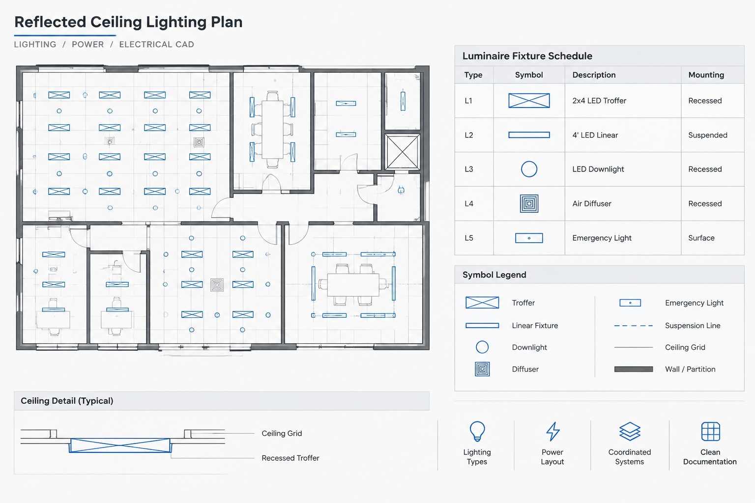
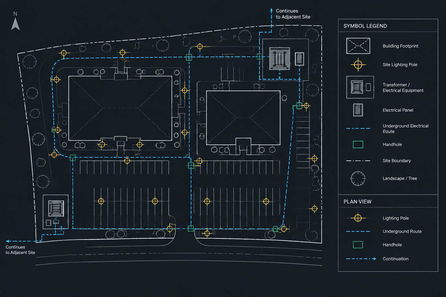
Use sheet-specific layer states carefully. A power plan and lighting plan may require different portions of the same background. For example, ceiling grids and architectural ceiling elements can be important on a lighting drawing but unnecessary on an underground pathway plan. Record intentional layer overrides so they are not mistaken for missing source information.
Separate electrical geometry from referenced geometry
Electrical symbols, tags, circuit lines, and notes should remain in controlled electrical files and layers. Avoid tracing background objects unless the duplicated linework has a defined documentation purpose. Traced walls and copied room names can become stale when the source changes, leaving two conflicting versions on the same sheet.
Place electrical blocks according to design intent rather than using the visual edge of a symbol as the only coordination point. Blocks should have logical insertion points, consistent orientation rules, and attributes that remain readable after a background update. Where exact equipment interfaces matter, coordinate against verified connection or footprint information instead of assuming that a generic block represents the final product.
Manage background updates as revisions
When a new architectural file arrives, preserve the previous exchange in an archive and record the new source information. Replace or reload the reference using the established path and coordinate method. Then compare the updated background with the prior condition.
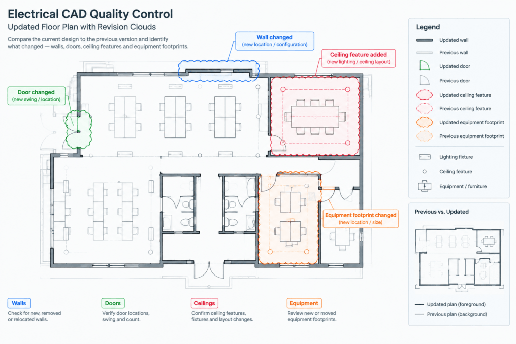
Focus the review on changes that can affect electrical documentation:
- Moved, added, or removed walls and doors
- Changed room names or room functions
- Revised ceiling layouts
- Shifted casework or fixed equipment
- Modified electrical room or service-area geometry
- Changed shafts, risers, stairs, or vertical openings
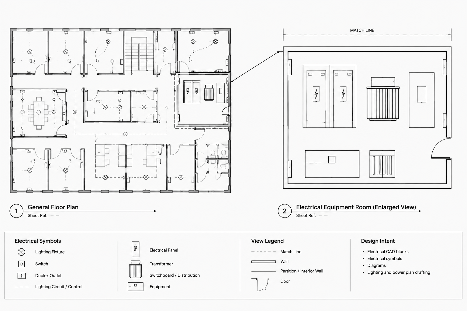
- Added match lines, enlarged plans, or area boundaries
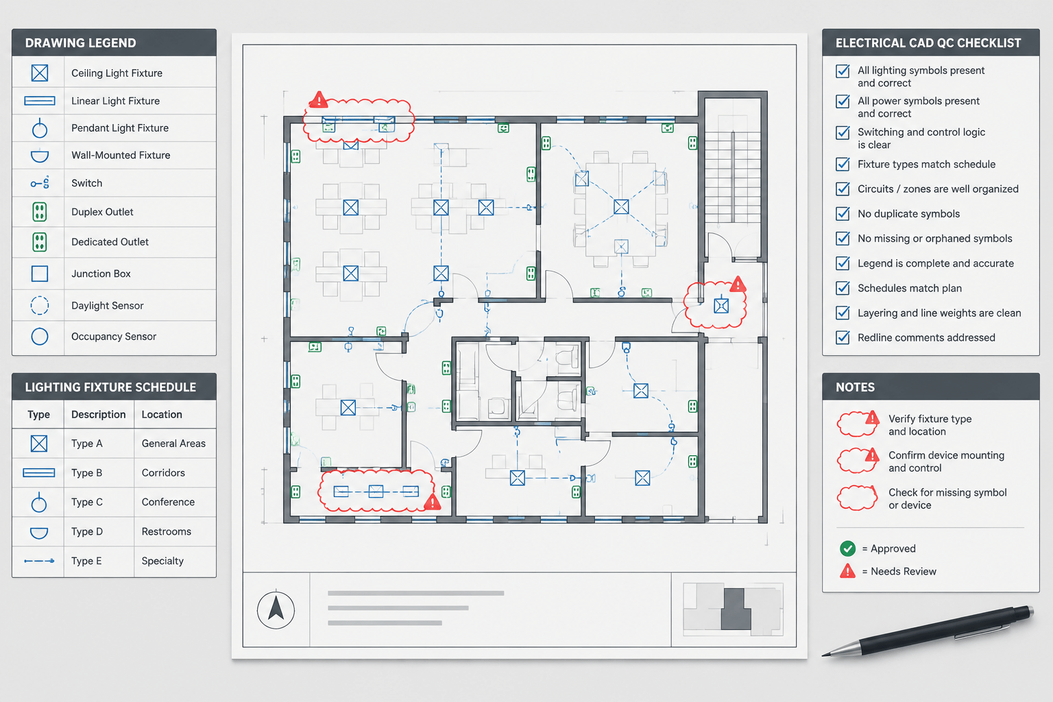
Do not rely only on a quick visual glance. Compare drawings using approved project tools or a structured side-by-side review, and mark items requiring electrical action. After changes are incorporated, remove temporary comparison graphics before issue unless they are intentionally part of the revision record.
Coordinate model files and sheet files
A common arrangement separates model content from sheet presentation. The electrical model contains design geometry, while a sheet file contains viewports, title information, and issue-specific annotations. In that structure, decide where architectural references belong and avoid attaching the same background redundantly at multiple levels.
The reference chain should be easy to explain: which file owns the electrical content, which file supplies the background, and which file presents the sheet. A complicated chain of nested files may work on one workstation but become fragile when transmitted. Simpler dependency structures are generally easier to audit and package.
Run a pre-issue xref check
Before plotting or transmitting an electrical set, review references in both the working environment and the final output.
- Confirm that every required reference is found and loaded.
- Check that file names correspond to the intended building areas and revisions.
- Verify position, scale, and rotation at multiple locations.
- Inspect reference layer visibility in each viewport or sheet view.
- Look for duplicated nested backgrounds.
- Confirm that electrical graphics remain visually dominant.
- Check that room names and key architectural features are readable.
- Inspect plotted or exported output rather than relying only on model-space display.
- Package required reference files when the recipient needs an editable drawing set.
A clean xref workflow protects more than file paths. It preserves the relationship between the electrical design and the building information on which that design depends. By controlling coordinates, reference types, layer appearance, updates, and issue checks, a CAD team can make background changes visible and manageable instead of allowing them to become hidden drawing errors.
Turn xref coordination into a project record
A repeatable workflow is easier to audit when each active background has a concise control record. This can be maintained in a drawing register, exchange log, or other project-approved tracking document. The purpose is to distinguish the background currently used for coordination from files that were merely received, reviewed, or archived.
- Reference identity: Record the file name, source discipline, building area, and intended use.
- Receipt and review status: Indicate when the file was received and whether it was accepted for active coordination.
- Coordinate basis: Note the approved origin, insertion, scale, and rotation method without relying on an undocumented manual adjustment.
- Reference behavior: Identify the selected path strategy and whether attachment or overlay behavior is intended.
- Display treatment: Record important layer overrides, clipping, or sheet-specific visibility decisions.
- Change impact: Track architectural revisions that require electrical review, redlines, or drawing updates.
- Issue status: Confirm whether the reference must be included in an editable handoff package or is represented only in plotted output.
Use visible symptoms to trace xref problems
Xref failures often provide clues about the affected part of the drawing dependency chain. Diagnose the cause before moving geometry, copying objects, or editing another discipline’s source file.
- Found on one workstation but missing on another: Review path resolution, project folder structure, access permissions, and transmitted dependencies.
- Uniformly shifted, rotated, or scaled content: Check source coordinates, insertion settings, drawing units, and any host-file transformations.
- Alignment differences limited to part of the plan: Investigate source revisions, design options, duplicate geometry, or actual changes to the building layout.
- Correct model display but incorrect plotted output: Review viewport overrides, layer states, plotting rules, and export settings.
- Duplicate background graphics: Trace nested references and check whether the same source was also attached directly in another model or sheet file.
- Missing coordination information: Determine whether layers are suppressed, the reference is clipped, nested content is unavailable, or the wrong source file is active.
Distinguish an editable handoff from a record output
An editable CAD handoff and a plotted record serve different purposes. A recipient who must continue working with the drawing may need the reference dependencies, support files, and usable folder relationships. A plotted or exported record must instead be checked for the intended visible result.
Binding or permanently incorporating a reference should not be treated as an automatic cure for packaging problems. It can alter layer organization, obscure source ownership, and complicate later updates. Use it only when the deliverable requirements and project workflow call for that result, and retain an auditable source version.
Frequently asked questions
Why does an architectural xref appear in the wrong location?
Common causes include inconsistent drawing units, a different source origin, an incorrect insertion point, unintended rotation, or a manual transformation applied in the host file. Verify the project coordinate method at separated control locations before repositioning anything.
Should an architectural background be attached or overlaid?
Use the behavior that matches the planned reference chain. Overlay can prevent a background from propagating through another host file, while attachment can preserve nested visibility when that is intentionally required. Review the complete model-and-sheet structure rather than choosing by habit.
Can an xref be clipped to improve sheet readability?
Yes, clipping can limit visible background content for a particular view. It does not remove the source geometry or replace coordination review. Confirm that the clipped area does not conceal information needed to understand electrical placement or design changes.
Should the electrical drafter clean up the architectural source file?
Generally, source problems should be documented and returned to the responsible discipline. Electrical teams can control reference display in their own files, but broad edits to another discipline’s background may hide coordination issues and create an unofficial version.
How should a revised background be evaluated?
Compare it with the previously coordinated version and review changes affecting rooms, walls, doors, ceilings, equipment, openings, and plan boundaries. Record required electrical actions instead of assuming that a successfully reloaded file needs no further review.
Why does an xref plot differently from how it appears in the model?
Viewport-specific layer overrides, plotting rules, display settings, and export behavior can change the final appearance. Inspect the issued output and confirm that the architectural context remains readable without overpowering electrical graphics.
Leave a Reply
You must be logged in to post a comment.