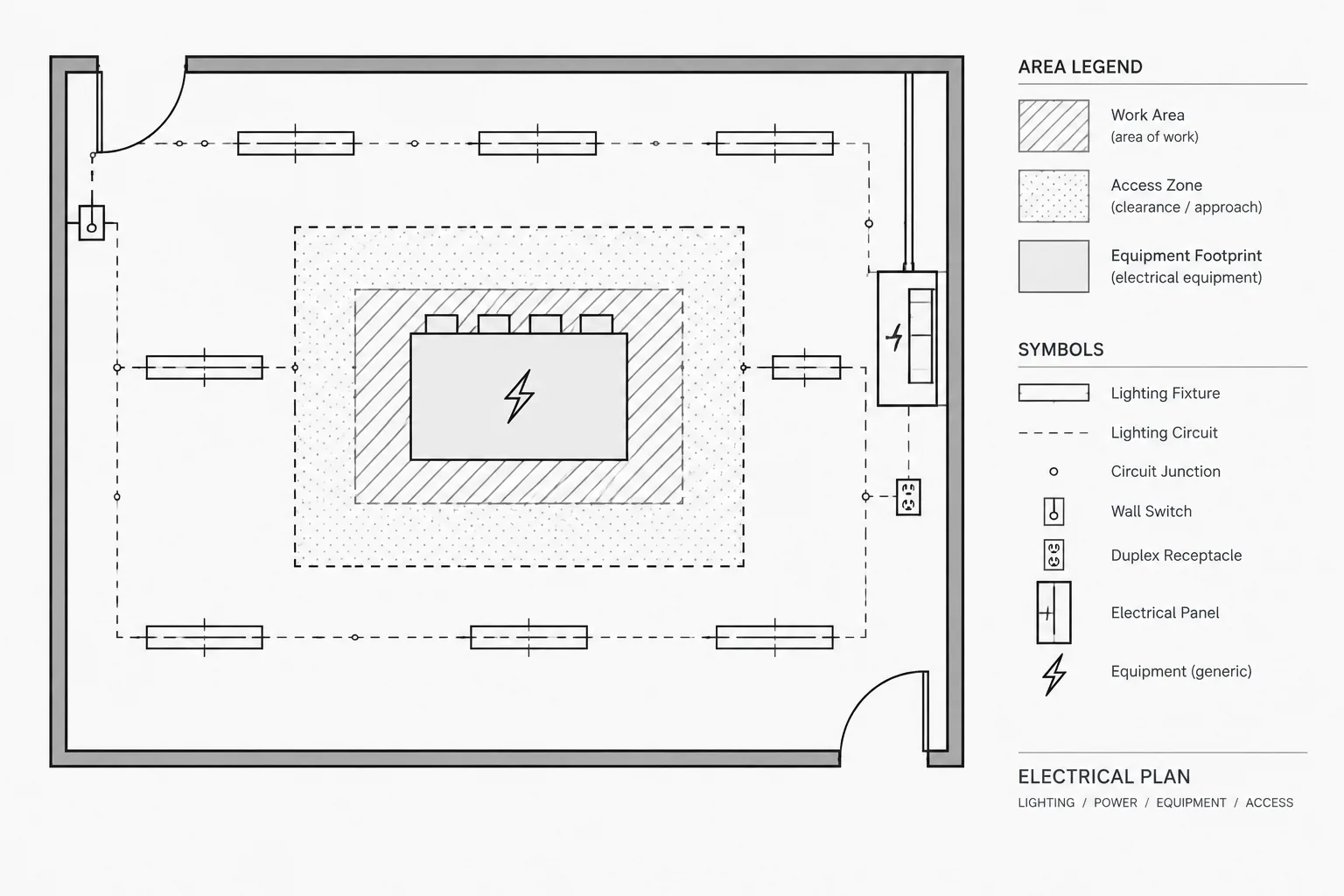
Electrical CAD hatch patterns are most effective when they clarify scope or spatial relationships without competing with the information that must be designed, coordinated, and reviewed. Pattern selection is only part of the task; boundary quality, layer control, draw order, plotting, and legend coordination determine whether the result remains readable.
The following guidance examines hatches, poche, screening, and outlines as parts of a coordinated drawing system. It focuses on practical drafting decisions that preserve the visibility of electrical symbols, routes, equipment interfaces, and annotations.
Electrical CAD hatch patterns can communicate scope, material, status, and spatial relationships more quickly than notes alone. They can also make a drawing nearly unreadable when patterns are too dense, extend beyond their intended boundaries, or compete with electrical symbols and circuiting.
The goal is not to fill every available area. A hatch or solid poche should answer a specific drawing question: What area is affected? Which object is being emphasized? Is the region accessible, restricted, existing, demolished, or part of a defined work zone? If the pattern does not add information, it is probably unnecessary.
This guide explains how to use hatches and poche as controlled documentation tools rather than decoration. Project requirements, office standards, client conventions, and plotting conditions should always be verified before a pattern is adopted.
Hatch, Poche, Screening, and Outlines Serve Different Purposes
Although these graphic methods are sometimes used interchangeably, they perform different jobs on an electrical drawing.
- Hatch: A repeated line or dot pattern applied within a closed boundary. It can identify a material, work area, route zone, or drawing status.
- Poche: A visually heavy fill, often solid or nearly solid, used to emphasize cut material, major equipment mass, or another dominant graphic element.
- Screening: A lighter plotted appearance used to reduce the prominence of background information while keeping it visible for context.
- Boundary outline: A closed polyline or similar object that defines an area without filling it. This is often the clearest choice when the interior contains many symbols.
Select the least visually aggressive method that communicates the intended information. A boundary with a label may work better than a patterned fill over a dense power plan. Poche may be effective for a small equipment footprint but overwhelming across a large room.
Useful Applications on Electrical Drawings
Defining Areas of Work
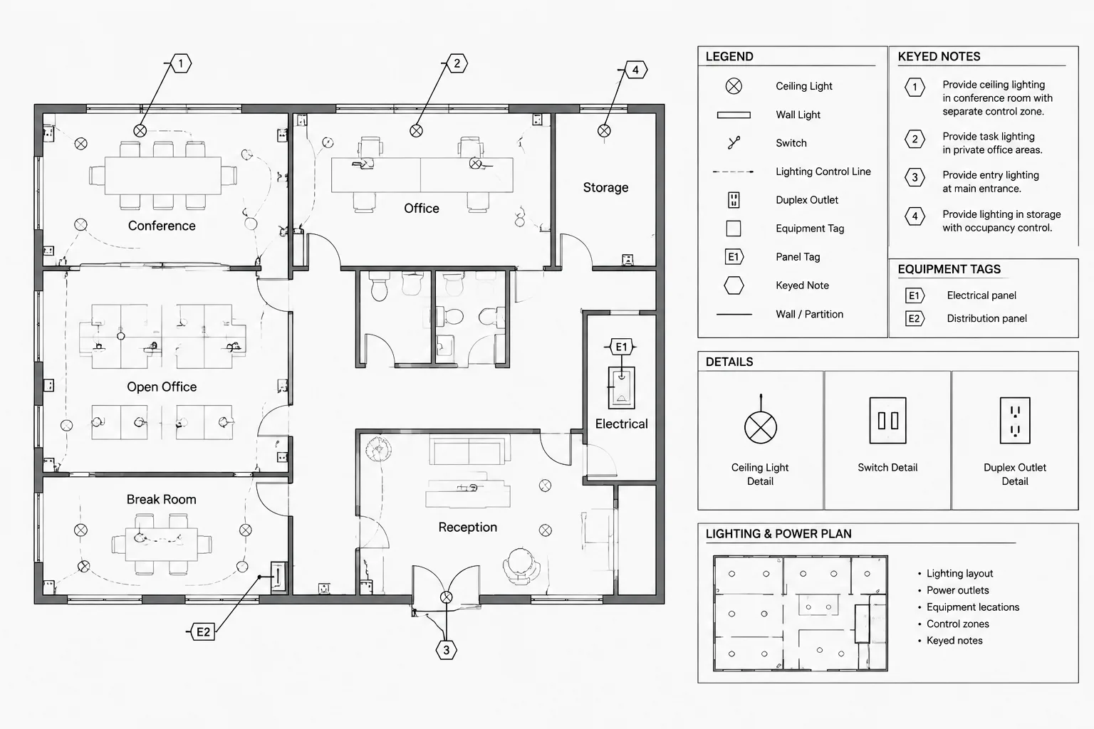
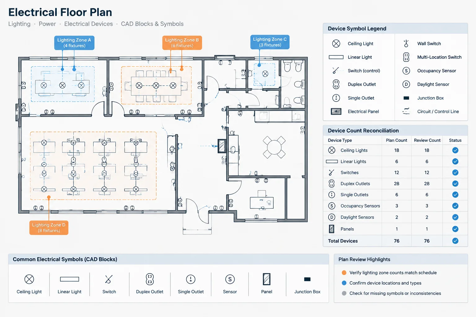
A hatch can distinguish a renovation zone, tenant area, project phase, alternate scope, or area served by a particular system. The boundary should be deliberate and traceable to recognizable architectural limits where possible.
Do not rely on the pattern alone. Add a label, keynote, or legend entry explaining what the area means. This is especially important when drawings may be printed in monochrome or reproduced at a reduced size.
Representing Equipment Footprints
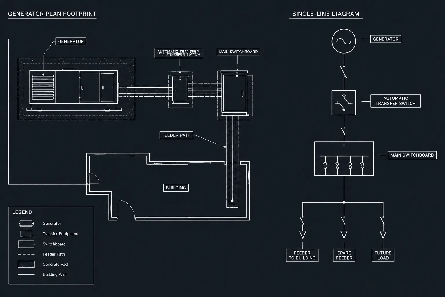
Light fills can help separate equipment footprints from walls, furniture, and other background objects. For example, a plan may use a restrained poche inside a major equipment outline while keeping access zones unfilled and independently labeled.
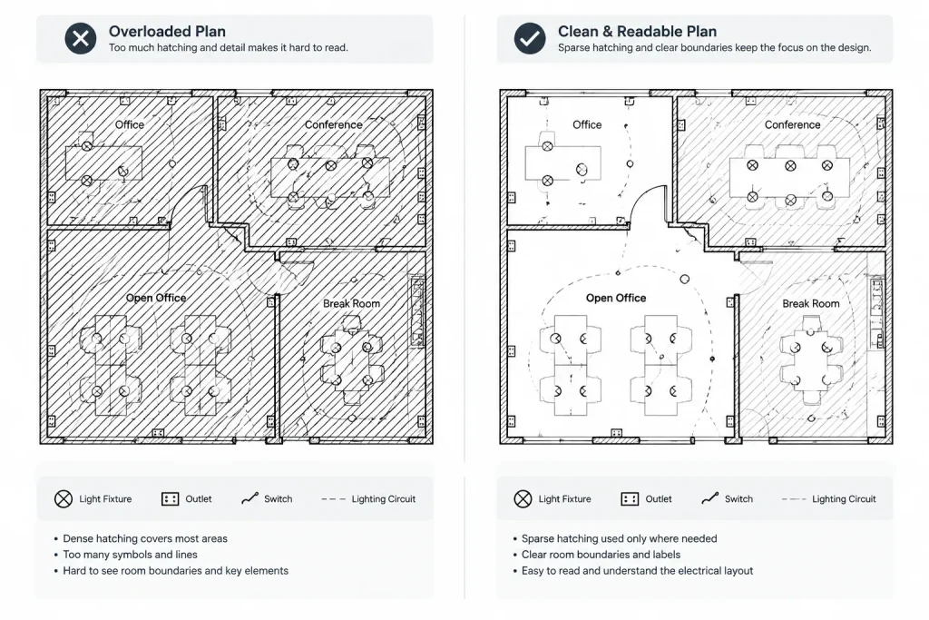
A filled footprint must not conceal connection points, tags, door swings, ventilation interfaces, or required coordination geometry. Where internal information matters, use a transparent-looking plotted treatment, a sparse hatch, or an outline instead.
Showing Access and Coordination Zones
Hatches may identify access zones, service areas, reserved pathway regions, or spaces that must remain unobstructed. These graphics should be treated as documentation overlays, not as decorative extensions of the equipment block.
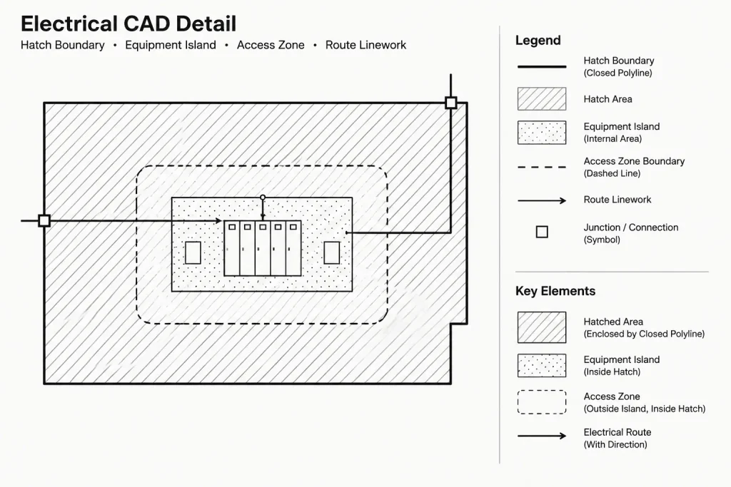
Keep the zone boundary editable and separate from the equipment footprint. That allows the zone to change without rebuilding the equipment symbol and helps reviewers distinguish physical geometry from coordination information. Any actual clearance criteria must come from verified project requirements and applicable references rather than from a generic CAD block.
Clarifying Underground and Concealed Work
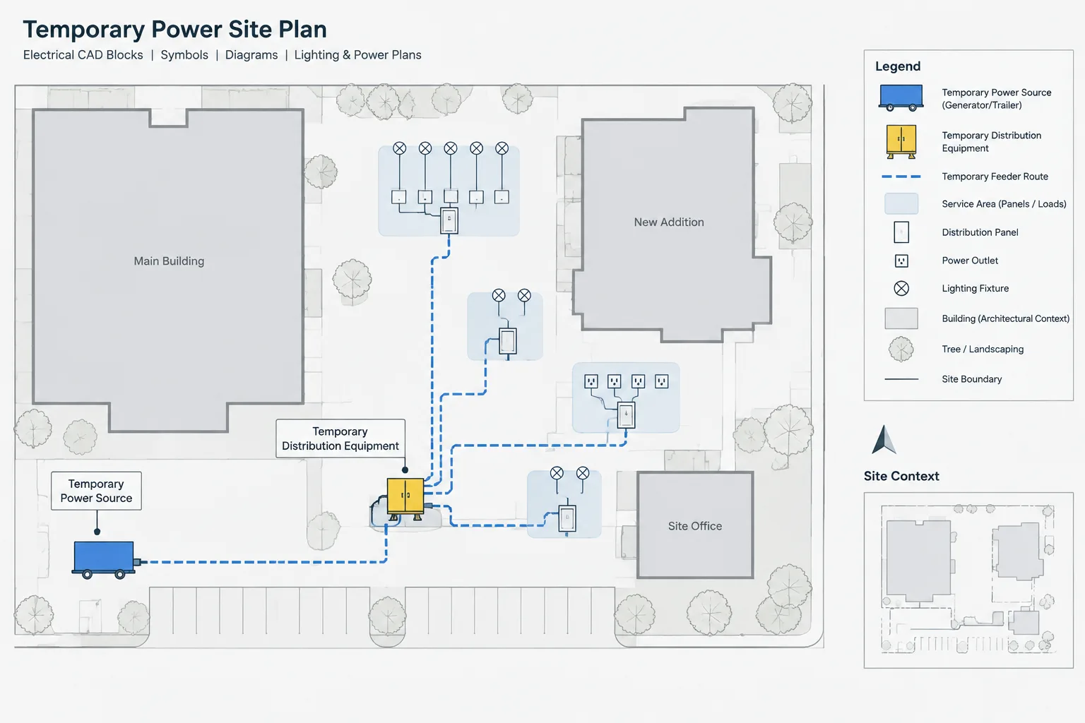
On site plans, enlarged plans, or sections, a hatch can help distinguish trench limits, backfill regions, encased routing zones, or areas of concealed work. The hatch should support—not replace—the lines representing raceways, duct banks, sleeves, or cables.
Sections often benefit from material hatches because the drawing depicts cut construction. Plans generally require more restraint because patterns can conflict with route lines, dimensions, and utility annotations.
Supporting Demolition and Existing-Condition Graphics
A pattern may identify a demolition area or a region affected by selective removal. However, the status of individual devices and circuits should still be communicated through the project’s established linework, tags, notes, and legends.
A broad demolition hatch does not explain whether every object inside the boundary is removed. If exceptions exist, state them clearly and use object-level status graphics where needed.
Choose Patterns by Communication Role
| Drawing purpose | Possible graphic treatment | Primary drafting concern |
|---|---|---|
| Area of work | Light, open hatch with labeled boundary | Keep devices and circuiting readable |
| Equipment footprint | Restrained fill or poche inside outline | Preserve tags, openings, and interfaces |
| Access or service zone | Sparse hatch or dashed boundary | Separate coordination space from physical equipment |
| Underground work area | Patterned region behind route linework | Avoid confusing the hatch with conduits or utilities |
| Sectioned construction | Material-oriented hatch | Maintain visible edges and penetrations |
| Scope or phase region | Distinct pattern plus text label | Remain understandable without color |
One pattern should have one meaning within a drawing set. Reusing the same hatch for unrelated purposes forces readers to depend on context and increases the chance of misinterpretation.
Build Reliable Hatch Boundaries
Unstable boundaries are a common source of drafting problems. Small gaps, overlapping segments, duplicate geometry, and complex imported backgrounds can prevent a hatch from generating correctly or cause it to flood an unintended area.
A reliable workflow is to create a dedicated closed polyline for the hatch boundary rather than asking the CAD application to infer a complex perimeter from surrounding architectural objects. The boundary can be placed on a controlled layer, reviewed independently, and revised without editing the background.
Where holes are needed around equipment, shafts, rooms, or excluded areas, confirm that the hatch recognizes those internal boundaries. After revisions, inspect the entire filled region instead of assuming that an associative update produced the intended result.
Control Layers and Draw Order
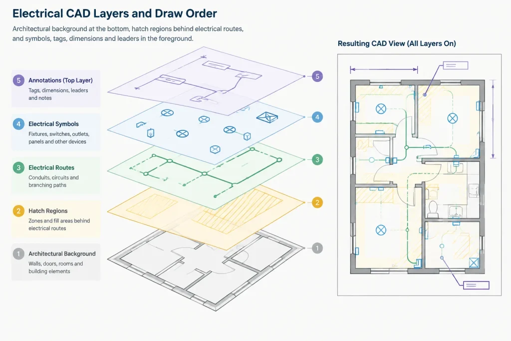
Place hatches on layers organized by purpose, not merely by pattern name. A layer name that communicates scope or function is more useful than one that says only “hatch.” Separate layers may be appropriate for work areas, equipment fills, access zones, underground regions, and section materials.
Keep hatch objects behind electrical symbols, tags, dimensions, leaders, and route linework. Solid fills deserve special attention because incorrect draw order can hide critical information while appearing acceptable in an uncluttered model-space view.
Do not place every fill on a single shared layer if different plan types need different visibility. Lighting, power, demolition, and coordination sheets may require independent control even when they reference the same base geometry.
Manage Pattern Scale and Origin
A hatch that looks balanced in model space may merge into a dark mass or disappear when plotted through a sheet viewport. Evaluate pattern scale using the intended output, not only the editing view.
Pattern origin also affects appearance. Adjacent regions using the same pattern may look misaligned if each begins from an arbitrary point. Alignment can be useful when separate areas are intended to read as one continuous material or scope region. Conversely, intentionally different origins should not be used as the only method of distinguishing categories.
Avoid extremely dense patterns. They can enlarge files, slow regeneration, obscure text, and reproduce poorly in PDF or print. Simplifying the pattern is usually better than trying to compensate with heavier linework elsewhere.
Do Not Depend on Color Alone
Color is useful during CAD production, especially for layer management and on-screen coordination. It is not always preserved in issued documents. A drawing may be printed in monochrome, screened by a plot style, or viewed on a device with different display settings.
Combine color with another distinguishing feature such as a boundary type, pattern, label, keynote, or legend entry. Test whether the meaning remains clear when all colors are removed. If two scope regions become indistinguishable in a monochrome preview, the graphic system needs another layer of communication.
Keep Legends Specific to the Drawing
Include hatch samples in the legend when their meaning is not self-evident. The sample should reflect the actual plotted appearance closely enough to be recognized. Use plain descriptions such as “area of renovation work” or “equipment access zone” rather than vague labels such as “pattern A.”
Do not retain unused hatch samples from a template. A legend containing patterns that never appear on the sheet creates uncertainty about missing scope or incomplete drafting.
Quality-Control Checklist
- Confirm that every hatch communicates a defined purpose.
- Verify that each pattern has one consistent meaning across the applicable sheets.
- Inspect closed boundaries for gaps, overlaps, unintended islands, and spillover.
- Check that symbols, tags, route lines, dimensions, and leaders remain visible.
- Review hatch layers in every relevant layer state and viewport.
- Test plotted output rather than relying only on model-space appearance.
- Review the drawing in monochrome to identify color-dependent distinctions.
- Confirm that legends include used patterns and omit unused ones.
- Check revised boundaries after architectural or equipment layout changes.
- Verify that generic fills do not imply unconfirmed materials, ratings, or construction requirements.
Use Hatches as a Supporting Graphic System
Effective electrical CAD hatch patterns establish hierarchy without becoming the drawing’s dominant feature. Symbols, circuits, equipment identifiers, routes, and annotations usually carry the primary technical information. Hatches should organize that information and provide context.
A restrained pattern, a clean boundary, and a direct label are often more successful than a highly detailed fill. By separating hatch purposes onto controlled layers, maintaining reliable boundaries, checking draw order, and reviewing actual plotted output, drafters can add useful visual structure while preserving the clarity of the electrical documents.
A Practical Selection Workflow
Before adding a fill, identify the exact question the graphic must answer. If the reader only needs to recognize the edge of a work area, a labeled outline may be sufficient. If the interior must be visually grouped, a light hatch may be appropriate. Reserve heavier poche for elements that genuinely require strong emphasis.
Next, consider what already occupies the region. Areas containing dense circuiting, device tags, dimensions, leaders, or coordination notes usually need a quieter treatment than open areas. The background should remain subordinate to the objects that carry design information.
Finally, review the result in the same presentation conditions expected for the drawing. Confirm the visible hierarchy in sheet view, monochrome output, and reduced viewing conditions. A pattern that appears subtle while editing can become dominant after plotting or conversion.
Coordinate Hatch Information Through Revisions
Hatches often depend on architectural rooms, equipment layouts, or project scope boundaries that change during design. Treat the hatch boundary as maintained documentation rather than a graphic that can be ignored after placement. When referenced geometry moves, verify the boundary, excluded islands, labels, and legend description together.
Associative behavior can reduce editing effort, but it does not replace review. Revised geometry may create unexpected openings, close intended gaps, or extend a pattern into an adjacent space. A visual check of the complete region is essential after updates.
Prepare Patterns for Drawing Exchange
Custom patterns may not display consistently when a file is opened in another environment or processed through a different plotting workflow. Where reliable exchange is important, use controlled office resources and keep the meaning recoverable through labels, outlines, and legends.
Recipients should not need a particular screen color or pattern file to understand the document. If a hatch fails to render, the remaining boundary and annotation should still communicate enough information for the issue to be identified and resolved.
Frequently Asked Questions
When is an outline better than a hatch?
An outline is often better when the enclosed area contains many electrical symbols, routes, dimensions, or notes. A labeled boundary can define the region without adding visual texture behind critical information.
Should equipment footprints and access zones use the same fill?
They should remain graphically distinguishable because they represent different information. The equipment footprint describes physical geometry, while an access or service zone is a coordination overlay. Separate boundaries and layers also make revisions easier to manage.
Why does a hatch look acceptable in model space but too dark on the sheet?
Viewport presentation, plot styles, output processing, and reduction can change the apparent density of a pattern. Evaluate the hatch through the intended sheet and plotting workflow rather than approving it only from the editing view.
Can color replace a hatch legend?
Color alone is not a reliable substitute for a legend. Drawings may be printed in monochrome or viewed under different display conditions. Pair color with a recognizable pattern, boundary, label, keynote, or other documented graphic distinction.
How should a hatch be checked after a background update?
Inspect the complete boundary, internal exclusions, draw order, labels, and plotted appearance. Confirm that the revision did not create spillover or conceal electrical information, even when the hatch is associative.
What should happen if a custom pattern may not transfer with the CAD file?
Keep the meaning understandable through a clear boundary and annotation, and follow the project’s file-exchange procedures. The drawing should not depend entirely on a custom pattern resource that another user may not have.
Leave a Reply
You must be logged in to post a comment.