
Electrical riser diagrams vs. single-line diagrams is primarily a comparison of drawing intent. Both use schematic linework, but each organizes information differently: one emphasizes electrical hierarchy, while the other adds clear building-level or zone relationships.
This reference explains how to select, organize, and coordinate these diagram types within an electrical drawing set. It also identifies when a combined view is useful and when separate drawings provide better clarity.
Electrical riser diagrams and single-line diagrams both simplify power distribution systems, but they do not always communicate the same information. A single-line diagram primarily explains electrical relationships: where power originates, how it passes through distribution equipment, and which feeders serve downstream loads. A riser diagram emphasizes how systems extend between building levels, areas, or vertical pathways.
The terms are sometimes used interchangeably, and drawing practices vary among firms and project types. A diagram may even combine both functions. For drafting purposes, the important question is not what the sheet is called, but whether it clearly communicates electrical topology, physical level relationships, equipment identification, and drawing references.
What Is an Electrical Single-Line Diagram?
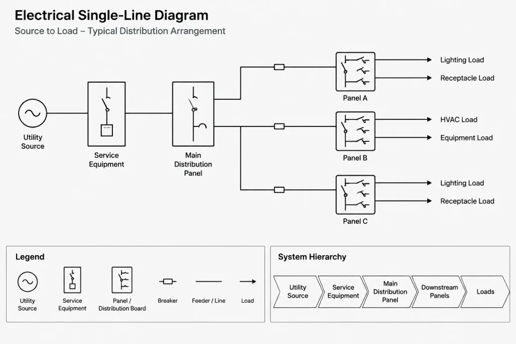
A single-line diagram, often called a one-line diagram, represents a multiphase electrical distribution system with simplified linework. Instead of drawing every conductor independently, one line represents an electrical circuit or feeder while tags, notes, and schedules provide additional information.
The diagram usually follows power from a source toward downstream equipment. Depending on project scope, it may show utility interfaces, service equipment, generators, transfer equipment, transformers, switchboards, panelboards, disconnects, motor control equipment, and major loads.
A single-line diagram is primarily relational. It helps a reader answer questions such as:
- What is the source of power for this equipment?
- Which distribution device is upstream?
- What equipment is connected downstream?
- Where does normal or alternate power enter the system?
- Which feeder tag, equipment identifier, or schedule entry applies?
- Where are protective and switching devices positioned within the distribution path?
The drawing is not usually intended to represent the actual physical route of every raceway. Lines should communicate connectivity first. Excessive bends added to imitate field routing can make system relationships harder to follow.
What Is an Electrical Riser Diagram?
An electrical riser diagram organizes system components according to floors, vertical zones, or other building divisions. It is especially useful where feeders, busways, communication backbones, life-safety circuits, or other services extend through several levels.
Horizontal bands or labeled divisions commonly represent floors or building areas. Equipment symbols are placed within the appropriate band, and vertical linework shows how the system continues between them. This gives the reader a simplified view of both connectivity and vertical organization.
A riser diagram may help answer:
- Which equipment is located on each building level?
- Where does a vertical distribution path begin and end?
- Which floors are served by a common riser?
- Where do feeders or system branches leave the vertical pathway?
- Which plan, enlarged view, shaft drawing, or detail provides more information?
- How does a repeated floor arrangement differ at an exception level?
A riser is still schematic. Placing a line in a shaft-like column does not prove its exact installed position, clearance, or routing. Physical conditions must be coordinated with plans, sections, equipment layouts, architectural backgrounds, and applicable project requirements.
Electrical Riser Diagram vs. Single-Line Diagram
| Drawing characteristic | Single-line diagram | Riser diagram |
|---|---|---|
| Primary emphasis | Electrical source-to-load relationships | Distribution between floors, zones, or vertical pathways |
| Typical organization | Upstream equipment flowing toward downstream equipment | Equipment arranged within level or area bands |
| Physical location | Often secondary to system topology | General level or zone relationship is prominent |
| Route representation | Schematic rather than a raceway routing plan | Schematic vertical continuity rather than an exact shaft layout |
| Common coordination targets | Equipment schedules, feeder data, panel schedules, and power plans | Floor plans, shaft plans, sections, equipment rooms, and pathway drawings |
| Best use | Understanding how power is distributed | Understanding how distribution extends through a building |
The distinction is not absolute. A vertically arranged single-line diagram may also function as a riser, while a riser may include detailed source, switching, and protective-device relationships. The drawing title and legend should make its intended scope clear.
When a Combined Diagram Works
A combined diagram can be effective when the system is compact enough to show source-to-load relationships and building levels without creating congestion. Level bands can establish vertical context while conventional one-line symbols preserve electrical logic.
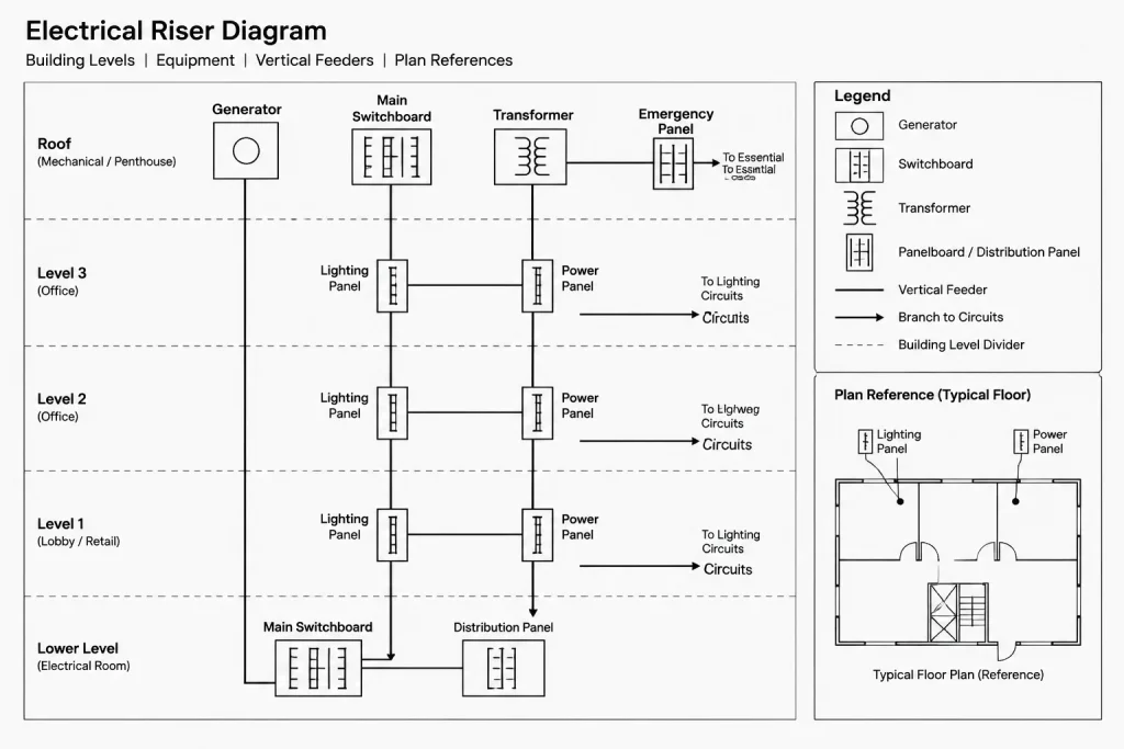
Combination becomes less successful when floor labels, feeder notes, equipment ratings, references, and branching lines compete for the same space. If readers must trace several crossing lines or search through dense text to find a connection, separate diagrams may be clearer.
Consider separating the drawings when:
- The main distribution network is complex but the vertical pathway is straightforward.
- Several systems share the same building riser or shaft.
- Repeated floors create more branches than one sheet can show legibly.
- Equipment details and feeder annotations obscure the level organization.
- Different disciplines or drawing packages require distinct system views.
CAD Layout Methods for Clear Diagrams
Establish a consistent reading direction
Choose a clear source-to-load direction and apply it consistently. A diagram may read from top to bottom, bottom to top, or across the sheet, but unexplained changes in direction can make upstream and downstream relationships ambiguous.
Create deliberate level bands
For risers, use aligned floor or zone labels and maintain visible separation between bands. Equipment should be placed within the band that reflects its documented location. If a symbol must be displaced for clarity, use a note or reference rather than allowing the diagram to imply a false location.
Use schematic linework intentionally
Orthogonal lines generally make distribution paths easier to trace. Avoid unnecessary jogs, closely spaced parallel lines, and unexplained crossings. Connection dots, crossing conventions, and termination symbols must be consistent with the project legend.
Separate graphics from project data
Reusable CAD blocks should contain stable symbol geometry, while attributes or adjacent text carry project-specific identifiers. This helps prevent a copied symbol from retaining an incorrect panel name, feeder reference, or equipment tag.
Control annotation density
Do not force every available data point onto the diagram. Information that belongs in a schedule can be referenced by a stable identifier. The diagram should contain enough information to understand the system and locate related documentation without becoming an unreadable substitute for every schedule.
Symbols and Tags That Need Coordination
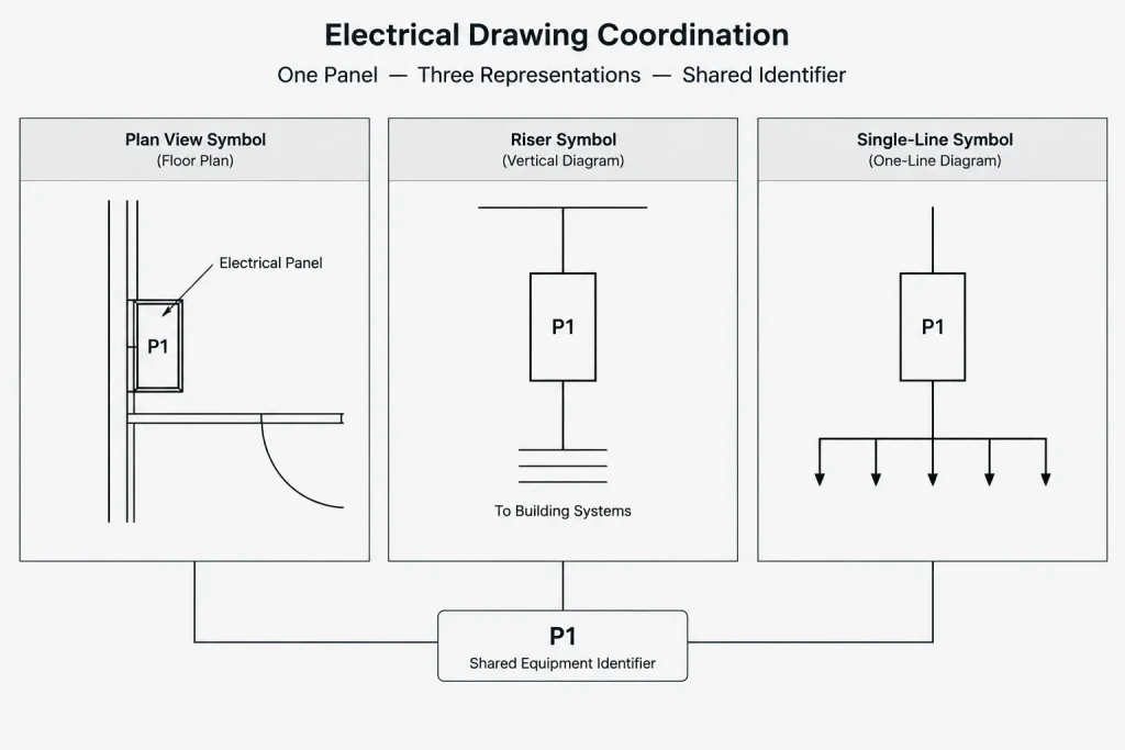
The same equipment may appear differently on plans, risers, and single-line diagrams. A panelboard might be represented by a plan-view wall symbol on a floor plan and by a schematic box or bus symbol on a diagram. Matching graphic appearance is less important than matching identity.
Coordinate these items across drawing types:
- Equipment tags and panel identifiers
- Source and destination references
- Feeder or circuit designations
- Transformer and transfer-equipment identifiers
- Normal, alternate, emergency, or other documented system classifications
- Existing, new, future, spare, or removed status notation
- Continuation arrows and off-sheet references
- References to plans, schedules, sections, and details
A symbol legend should explain graphic meaning, but it should not be used to repair inconsistent tagging. If the same identifier points to different equipment on separate sheets, the drawing set requires coordination rather than another legend note.
A Practical Drafting Workflow
- Define the diagram’s purpose. Decide whether the drawing must emphasize topology, vertical organization, or both.
- List the documented equipment. Build a controlled equipment list using the project’s plans, schedules, and design information.
- Arrange the major hierarchy first. Place sources, main distribution equipment, transformations, and principal downstream groups before adding minor branches.
- Add level or area structure. For a riser, establish floor bands or zones before locating equipment symbols.
- Connect equipment logically. Confirm every line has a clear origin and destination. Avoid decorative linework that could be mistaken for a connection.
- Apply identifiers and references. Use consistent tags that lead readers to related plans, schedules, and details.
- Compare all drawing views. Check that equipment shown on the diagram appears where expected on the plans and that scheduled items have corresponding diagram references when required.
- Plot-test the sheet. Review the issued-size output for line separation, text readability, crossing clarity, and reference visibility.
Common Documentation Errors
- Treating the diagram as a routing plan: Schematic connections are mistaken for exact raceway paths.
- Assigning equipment to the wrong level: A symbol is graphically convenient but conflicts with the floor plan.
- Using unmatched identifiers: A panel or transformer has different tags on the plan, schedule, and diagram.
- Leaving continuation lines unresolved: A feeder exits the sheet without a destination or off-sheet reference.
- Overloading repeated floors: Typical arrangements and exceptions are mixed without clear notation.
- Copying obsolete branches: Revised plans no longer contain equipment that remains on the diagram.
- Relying on color alone: System distinctions disappear in monochrome plots or low-quality review copies.
Final Quality-Control Review
Before issue, trace each major path from source to destination. Confirm that branching points are intentional, line crossings are unambiguous, and every diagram symbol has a coordinated identity. For a riser, verify the assigned floor or zone against the plan. For a single-line diagram, verify the upstream and downstream relationships against schedules and equipment documentation.
A well-drafted single-line diagram explains the electrical hierarchy. A well-drafted riser explains how that hierarchy extends through the building. Whether they appear separately or as a combined drawing, both should serve as controlled navigation tools within the larger electrical document set—not as isolated sketches.
Choosing the Right Diagram for the Documentation Task
Begin with the question the drawing must answer. If reviewers need to trace power from its source through distribution equipment to downstream loads, a single-line diagram is generally the clearer organizational model. If they need to understand how distribution continues between floors, shafts, or building zones, a riser arrangement gives that physical hierarchy greater prominence.
The decision does not need to be based on terminology alone. A project may use a combined diagram when electrical relationships and level organization remain easy to read together. When branching, annotations, references, or repeated conditions make the sheet difficult to follow, separating the views can reduce ambiguity.
Documentation Boundaries to Preserve
Neither diagram should be treated as a replacement for coordinated plans, schedules, sections, equipment layouts, or pathway details. Diagram lines establish documented connections, but they do not automatically define exact raceway routing or installed position.
- Use the diagram for relationships: Show how identified equipment and distribution paths connect.
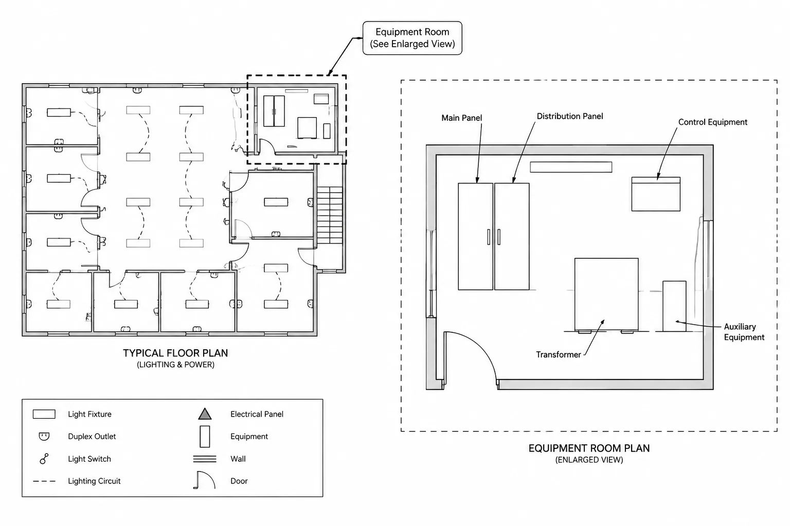
- Use plans for location: Coordinate equipment placement and general pathway information with the applicable plan views.
- Use schedules for structured data: Reference project information through consistent identifiers rather than crowding the diagram.
- Use details and sections for physical coordination: Direct readers to views that explain arrangements not resolved by schematic linework.
Revision Control Across Drawing Types
A diagram remains reliable only when it changes with the rest of the document set. When equipment is renamed, relocated, removed, or reassigned, review the plans, schedules, risers, single-line diagrams, and associated references together. A visually clean diagram can still be misleading if its identifiers or connections no longer agree with related sheets.
During quality control, trace each connection and verify both ends against the current documentation. Also check continuation symbols, level assignments, status notation, and references. This relationship-based review is more effective than checking each sheet in isolation.
Frequently Asked Questions
Is an electrical riser diagram the same as a single-line diagram?
Not necessarily. A single-line diagram emphasizes electrical source-to-load relationships, while a riser diagram emphasizes how a system extends between building levels, zones, or vertical pathways. Some project drawings combine both functions.
Can a single-line diagram show building floors?
Yes. Level bands or zone labels can be added when they improve coordination without obscuring electrical topology. If the level structure becomes the dominant organizing feature, the drawing may also function as a riser.
Does a riser diagram show exact conduit or raceway routing?
Usually not. A riser is schematic and communicates continuity and general level relationships. Exact routing and physical coordination must be reviewed in the applicable plans, sections, layouts, and project details.
When should riser and single-line information be separated?
Separate drawings may be clearer when branching, repeated floors, dense annotations, several systems, or numerous references make a combined diagram difficult to trace.
Should equipment symbols look identical on plans and diagrams?
No. Plan symbols and schematic symbols may differ because they serve different purposes. Their equipment identifiers, status, references, and documented relationships should remain coordinated.
What is the most important CAD quality check for these diagrams?
Trace each major path from its source to its destination and confirm that connections, equipment tags, level assignments, continuation references, schedules, and plan locations agree.









Leave a Reply
You must be logged in to post a comment.