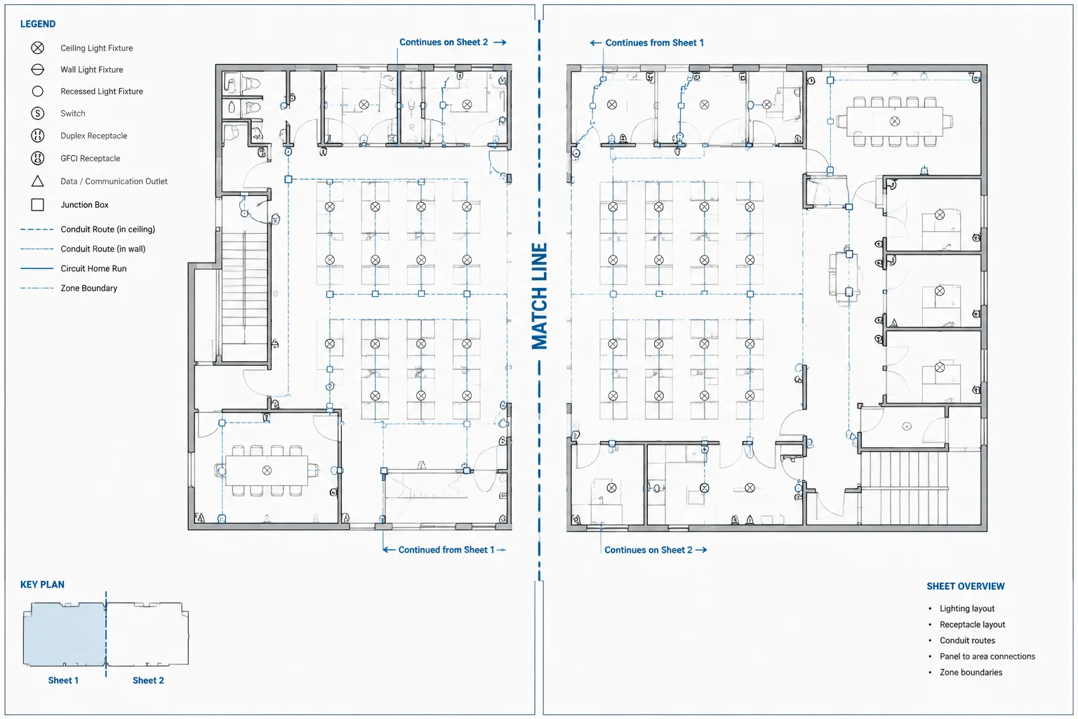
Electrical match lines in CAD connect partial plan views so a large floor plan can be read as one coordinated drawing. They define where coverage changes, identify the adjoining view, and preserve the continuity of circuits, pathways, controls, and equipment relationships across sheets.
The drafting challenge is not simply drawing a boundary. The match line must agree with viewport limits, overlap rules, key-plan graphics, area names, and reciprocal references. The following guidance focuses on organizing these elements so the issued sheets remain understandable without access to the underlying CAD model.
Large electrical floor plans often cannot be shown legibly on a single sheet. A building wing, parking level, production area, or campus floor may need to be divided into several enlarged plan views. Match lines identify where one view stops and the adjoining view continues.
A match line is more than a graphic boundary. It is a navigation and coordination device that affects circuiting, raceway routes, equipment identification, key plans, and revision control. If its placement or labeling is unclear, reviewers may overlook devices, interpret duplicated graphics as additional scope, or lose track of a circuit that continues onto another sheet.
This guide explains how to plan, draft, label, and review electrical match lines in CAD without treating them as arbitrary sheet-cutting marks.
What an Electrical Match Line Communicates
A match line marks the limit of a partial plan view and directs the reader to the adjacent drawing area. It commonly communicates three things:
- where the displayed plan coverage ends;
- which sheet or view contains the continuation; and
- how the two plan areas relate spatially.
The architectural floor plan may continue beyond the match line even though it is clipped or screened in the plotted viewport. Electrical circuiting, conduit routes, cable tray, feeders, control zones, and device groups can also cross that boundary. The drawing set must make those continuations understandable.
Match lines differ from property lines, phase boundaries, demolition limits, area separation lines, and scope boundaries. Those lines describe project conditions or responsibilities. A match line primarily organizes drawing coverage. Its linetype, label, and legend description should prevent confusion with other boundaries.
Plan the Sheet Division Before Drafting the Match Lines
The best locations come from studying the plan content rather than dividing the building into visually equal pieces. Begin with the intended plotted scale, usable sheet area, annotation density, and the natural organization of the building.
Prefer recognizable building breaks
Where practical, place a split near a corridor, expansion joint, structural separation, open area, or other recognizable feature. A reader should be able to compare adjoining sheets and quickly understand where they connect.
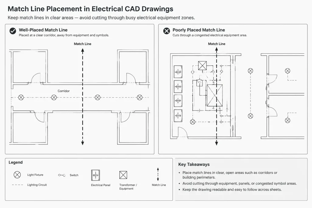
Avoid cutting directly through congested electrical rooms, dense equipment groups, panel locations, or complicated control areas when another location is available. Splitting a tightly coordinated assembly creates more continuation notes and increases the chance that related information will be reviewed separately.
Evaluate electrical systems crossing the boundary
Before fixing the split, inspect the systems that pass through it. Depending on the plan type, these may include:
- branch-circuit linework and home-run graphics;
- feeders, raceways, cable tray, or underground routing;
- lighting control zones and control connections;
- fire alarm, security, or communications pathways;
- equipment connection lines and interlocks;
- demolition work that continues into another area; and
- revision limits or phased-work boundaries.
A match line should not conceal a change in system designation. If a route changes identity, elevation, installation condition, or drawing reference near the boundary, keep the necessary annotation visible on the appropriate sheet.
Create Deliberate Overlap Between Adjacent Views
Adjacent plan views usually benefit from a controlled overlap. Shared architectural features help readers align the two sheets, while selected electrical graphics provide context for continuing systems.
Overlap does not mean showing all electrical scope twice without explanation. Duplicate device symbols can be mistaken for additional devices, especially during counting or quantity extraction. Establish a project rule for objects within the overlap area. One sheet may be designated as the primary location for tagging and circuit information, while the adjoining sheet shows only enough screened or reference information to maintain context.
The rule should be consistent across the drawing set. If duplicate graphics are intentionally plotted, distinguish them from primary scope through notes, display hierarchy, or view limits rather than relying on subtle differences that may disappear in a monochrome PDF.
Drafting and Labeling the Match Line
Place match-line graphics on a dedicated, consistently named layer or another clearly controlled annotation layer defined by the project CAD standard. This makes it easier to manage visibility, plotting, and updates independently of the architectural background.
A practical match-line assembly can include:
- a prominent boundary line with a recognizable linetype;
- text identifying the adjoining sheet or view;
- a directional phrase such as continuation or match to;
- orientation that keeps the note readable from the sheet’s normal viewing direction; and
- a corresponding reference on the neighboring plan.
Do not rely only on a sheet number if a sheet contains multiple plan views. Include enough information to identify the destination unambiguously, such as a view title, area designation, or detail reference when the project convention requires it.
| Match-line element | Drafting purpose | Common coordination risk |
|---|---|---|
| Boundary graphic | Defines the end of plan coverage | Confusion with scope or phase boundaries |
| Continuation reference | Directs the reader to the adjoining view | Outdated sheet or view identifier |
| Overlap area | Provides visual alignment and context | Devices or routes appearing as duplicate scope |
| Key-plan highlight | Shows the current plan area within the whole floor | Highlighted area not matching the viewport |
| Crossing annotations | Preserves system identity across the split | Lost circuit, raceway, or control continuity |
Coordinate Circuiting and Routes Across Sheets
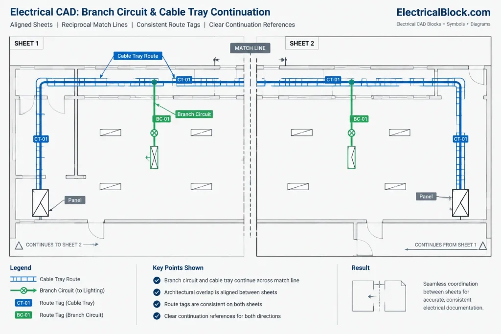
Electrical linework should approach a match line in a way that makes continuation evident. A route that simply stops at the view boundary can appear incomplete. Continue it to the match line and provide the adjoining reference where needed. On the next sheet, resume it from the corresponding location with the same identification.
For branch circuits, avoid creating an artificial home run merely because the circuit leaves the sheet. The drawing should distinguish a sheet continuation from an actual circuit origin or termination. Preserve panel and circuit designations according to the project documentation method.
For conduit, tray, and feeder routes, coordinate route tags on both sides of the split. A reader should not have to infer whether two unlabeled segments represent the same pathway. Where several routes cross close together, stagger labels and continuation graphics to prevent ambiguous pairings.
Control diagrams and plan connections may use separate cross-reference methods. If a lighting control line crosses a floor-plan match line, maintain the plan relationship while also preserving references to the applicable diagram, sequence, or detail. The match line should not replace system-level documentation.
Coordinate Match Lines with Viewports and Key Plans
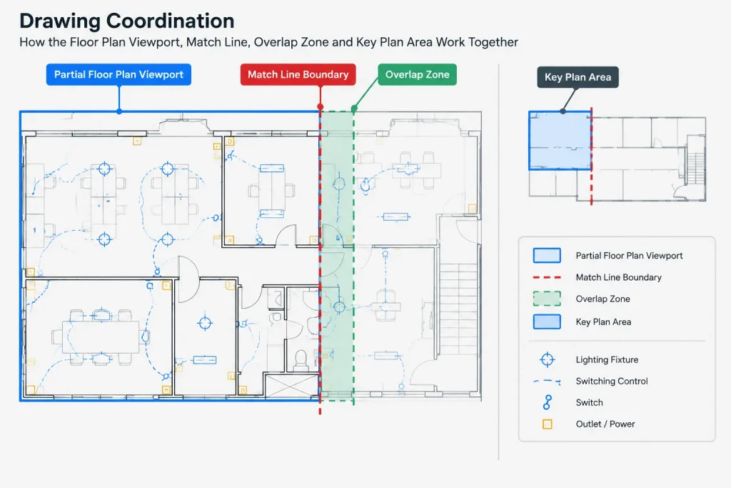
The drawn match line, viewport crop, and key-plan coverage must describe the same area. Moving one without updating the others can produce gaps, excessive overlap, or misleading area highlights.
Keep match lines in a controlled source location rather than recreating unrelated copies in several layouts. Depending on the office workflow, the graphic may be managed in model space, through referenced annotation, or with layout-specific content. The important principle is to maintain one coordinated boundary definition and verify every plotted result.
Each partial-plan sheet should also use consistent area names. If the key plan calls an area by one name while the match-line note uses another, navigation becomes unnecessarily difficult. Area names should remain stable between lighting, power, low-voltage, and demolition sheets unless a clear reason requires a different division.
Manage Changes Without Breaking References
Sheet organization often changes during design. A plan may be divided differently, a new sheet may be inserted, or a view may be relocated. Match-line references then require a coordinated update.
When coverage changes, review more than the visible label. Check:
- the references on both sides of every affected match line;
- viewport limits and any clipping boundaries;
- key-plan highlights and area titles;
- continuing circuits, feeders, pathways, and control lines;
- device tags located in overlap zones;
- sheet index and cross-reference information; and
- revision markings that may span the revised boundary.
Where CAD attributes or linked sheet data are used, they can reduce manual retyping, but they do not eliminate the need for visual review. A reference may contain the correct identifier and still point to the wrong physical area.
Match-Line Quality-Control Workflow
Review adjacent sheets side by side, preferably in the same format that will be issued. Begin at one end of the boundary and trace every crossing item to the corresponding location on the neighboring sheet.
- Confirm that both sheets reference each other correctly.
- Compare recognizable architectural features in the overlap.
- Trace every circuit, raceway, tray, feeder, and control connection across the line.
- Check that device symbols in the overlap are not counted or tagged inconsistently.
- Verify that area names and key-plan highlights agree with actual coverage.
- Inspect the plotted lineweight and text readability.
- Repeat the review for every discipline-specific electrical plan using the same split.
A useful final test is to ask whether a reader unfamiliar with the CAD file can move from one sheet to the next without guessing. If the continuation depends on layer knowledge, object selection, or an unstated office convention, the plotted documentation needs more clarity.
A Match Line Is Part of the Drawing Navigation System
Well-drafted electrical match lines help a large plan behave like one continuous document even when it occupies several sheets. Their effectiveness depends on thoughtful placement, controlled overlap, reciprocal references, and careful treatment of every system crossing the boundary.
Rather than adding match lines after sheet layouts are complete, include them in the initial plan-organization workflow. Coordinating them with viewports, key plans, circuiting, route tags, and revisions produces drawing sets that are easier to navigate, review, and maintain.
Choosing a Maintainable CAD Method
A match-line system should be easy to revise without creating unrelated copies of the same information. The most appropriate CAD method depends on how the project manages model content, layouts, referenced files, and sheet data.
Some teams use a reusable annotation block containing the boundary label and continuation reference. Others manage the line and text as controlled annotation objects. Either approach can work when the plotted appearance is consistent and the destination can be updated without overlooking the corresponding reference on the adjoining sheet.
Separate geometry from changing reference data
The physical boundary and its destination label do not always change at the same time. Keeping these components logically organized helps prevent a revised sheet identifier from affecting the boundary location, or a moved boundary from leaving an apparently valid but spatially incorrect reference.
If attributes, fields, or sheet-linked data are used, treat them as coordination aids rather than substitutes for review. Automated text can confirm a destination name while still failing to show whether the adjacent viewport covers the correct part of the plan.
Test the issued appearance
Match-line clarity should be evaluated in the plotted deliverable, not only in the CAD workspace. Layer colors, transparency, screening, clipping, and background linework can produce a result that differs from the editing view. Confirm that the boundary remains distinct from scope limits, demolition graphics, revision markings, and architectural separation lines.
Document the Project Match-Line Convention
A short drawing note or CAD guideline can define how overlap content, device tags, continuation labels, and key-plan highlights are handled. A documented convention is particularly helpful when lighting, power, communications, and demolition plans share the same sheet divisions but are produced by different team members.
The convention should identify which view controls information in an overlap area and how contextual graphics are distinguished from primary scope. It should also establish whether references are maintained through blocks, linked data, or manual annotation. Consistency matters more than choosing a complicated drafting method.
Final Coordination Perspective
A successful match line links spatial coverage and electrical information at the same location. The neighboring sheets should agree on building geometry, route identity, device treatment, area naming, and drawing destination. When those relationships are reviewed together, the match line becomes a reliable navigation tool rather than a decorative edge around a viewport.
Frequently Asked Questions About Electrical Match Lines
Is a match line the same as a scope boundary?
No. A match line identifies where drawing coverage continues on another view or sheet. A scope boundary describes responsibility, work limits, phasing, or another project condition. Distinct graphics and labels help prevent the two from being confused.
Should electrical objects appear on both sides of an overlap?
Selected objects may appear in both views when they provide alignment or continuation context. The drawing convention should make clear which view contains the primary tag, circuit information, or scope representation so duplicated graphics are not interpreted as additional work.
Should a circuit home run be added where it crosses a match line?
Not merely because the circuit leaves the sheet. A sheet continuation is different from an actual circuit origin or termination. The linework and references should preserve the circuit identity across the boundary without creating a misleading home-run graphic.
Can match lines be placed in model space or a layout?
Either workflow may be used when it follows the project CAD standard. The key requirement is coordinated control of the boundary, viewport coverage, reference text, and plotted appearance. Unmanaged copies in separate locations are more likely to become inconsistent.
What should be checked after a sheet reference changes?
Review both sides of the match line, the adjacent viewport, key-plan coverage, area titles, crossing systems, overlap graphics, and related sheet references. Correct text alone does not confirm that the destination view shows the intended physical area.
Why should adjoining sheets be reviewed together?
Side-by-side review reveals gaps, unintended duplication, displaced routes, inconsistent tags, and mismatched architectural features that may not be obvious when each sheet is checked independently.










Leave a Reply
You must be logged in to post a comment.