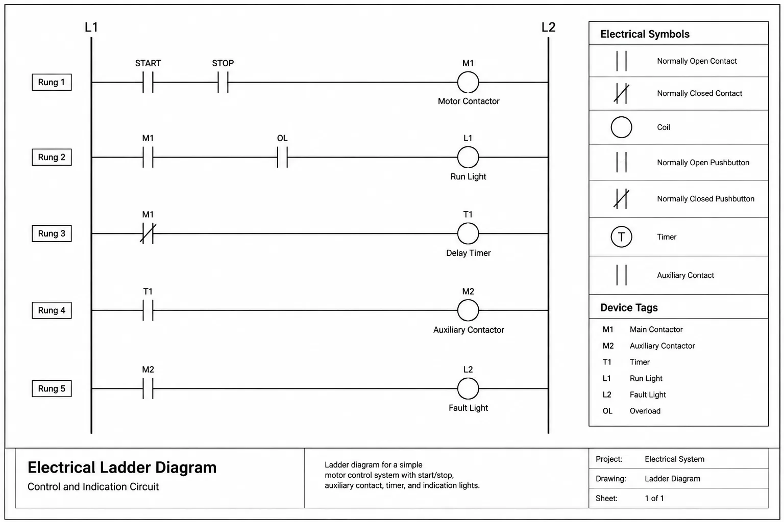
To draft electrical ladder diagrams in CAD effectively, treat the drawing as coordinated control documentation rather than a collection of disconnected symbols. Rail organization, rung readability, device identification, and contact-to-coil references must work together so reviewers can follow the intended logic.
The guidance below focuses on drafting structure, symbol management, annotation, and drawing coordination. Project-specific conventions and design requirements should always be confirmed before a diagram is issued or used as the basis for related documentation.
An electrical ladder diagram presents control logic as a sequence of horizontal circuits arranged between vertical reference lines. Its ladder-like structure helps readers follow the conditions that operate relays, contactors, solenoids, pilot devices, and other control functions. Although the format is visually simple, a useful ladder drawing depends on disciplined symbol use, consistent device identification, and reliable cross-references.
Drafting a ladder diagram in CAD is not merely a matter of placing contacts and coils. The drawing must communicate logical relationships while remaining coordinated with equipment schedules, wiring drawings, terminal plans, panel layouts, and related schematics. This guide explains a practical documentation workflow without addressing hands-on work on energized equipment.
What a ladder diagram communicates
A ladder diagram, sometimes called an elementary control diagram, primarily describes functional logic. Each rung represents a control path or related portion of a control sequence. Contacts indicate the conditions that permit or interrupt that path, while a coil or another output symbol usually appears toward the end of the rung.
The diagram is generally read across each rung and then through the drawing in the established rung order. The exact source and return arrangement, operating-state convention, and symbol system should be confirmed from the project requirements and applicable drafting practices.
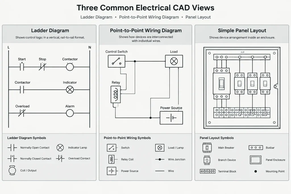
A ladder diagram is different from several related drawing types:
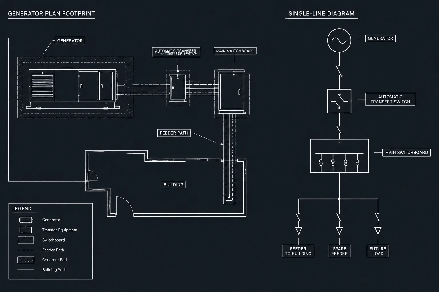
- Single-line diagram: Summarizes power distribution and major equipment relationships rather than detailed control logic.
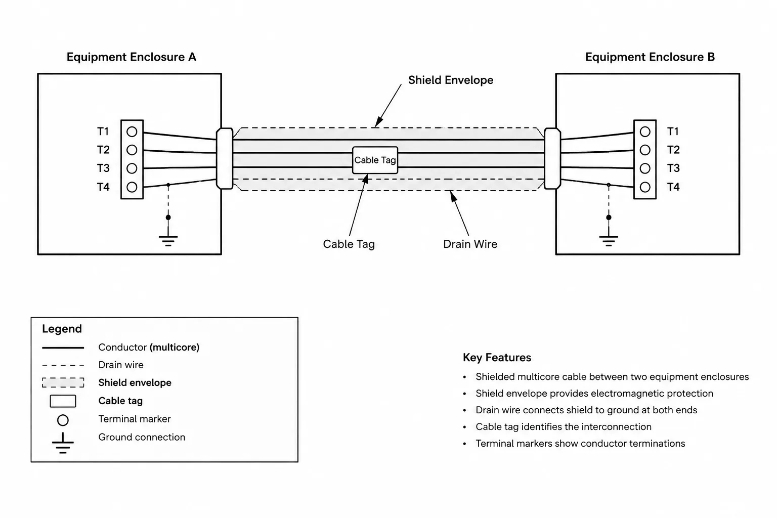
- Wiring diagram: Emphasizes physical conductors, terminals, and point-to-point connections.
- Panel layout: Shows the physical arrangement of components inside or on an enclosure.
- Sequence description: Explains operation in written form and may include conditions that are difficult to show graphically.
- Programmable controller documentation: May show programmed logic, input and output assignments, or software references that must be coordinated with, but should not automatically be treated as identical to, hardwired ladder logic.
Establish the drawing structure before placing devices
Begin with a repeatable sheet or diagram framework. Set up the rails, rung area, title information, continuation zones, and reference columns before drafting the control logic. This prevents individual rungs from growing without regard to the available drawing space.
Rails and functional boundaries
Draw the vertical rails as clear organizing elements. Their labels should identify the control reference used by the project without implying unverified electrical characteristics. If different control sources or functional sections appear in the same drawing set, label the boundaries prominently rather than relying only on line style or sheet position.
Do not use a rail as a generic visual border if it has a defined electrical meaning. Sheet frames, zone dividers, and control rails should remain visually distinguishable.
Rung spacing and reading order
Use consistent rung spacing wherever practical. Leave enough room for symbols, device tags, wire references, operating notes, and future revisions. Dense rungs can be divided using clearly identified continuation references, but a continuation should never leave the reader guessing where the logic resumes.
Assign each rung or logic group a stable reference. Rung references support design review, written sequences, contact cross-references, and troubleshooting documentation. Avoid renumbering the entire drawing for a minor insertion when the project workflow allows a controlled intermediate reference.
Build a controlled CAD symbol set
A shared symbol library reduces graphic variation and makes ladder diagrams easier to review. Typical categories include normally open contacts, normally closed contacts, relay or contactor coils, selector devices, pushbuttons, limit or sensing contacts, timers, pilot indications, protective contacts, and terminal references.
Each block should have a deliberate insertion point and predictable orientation. Place the insertion point on the intended connection line so symbols align without manual trimming. Avoid scaling symbols independently to force them into a rung; inconsistent symbol proportions make a diagram look assembled from unrelated sources.
Useful block data may include:
- Device tag
- Contact designation
- Terminal identification
- Drawing or rung reference
- Function description
- Related equipment tag
- Status or revision note when required by the project
Attributes can improve consistency, but they do not replace visual checking. An attribute may contain the correct value while being hidden, misplaced, duplicated, or associated with the wrong symbol.
Draft each rung as a statement of logic
Before drawing a rung, summarize its purpose in plain language. For example, a conceptual statement might say that an output is permitted when required control conditions are satisfied and is prevented by an interlock. Translating the intended operation into words first helps expose missing conditions and ambiguous contacts.
Place series conditions in a clear reading sequence. Use parallel branches to express alternate logic paths, holding functions, or other intentional relationships. Branches should connect with visible junctions where a connection exists. Avoid intersections that could be mistaken for junctions.
Keep the principal output visually easy to locate. If a rung contains multiple outputs or several unrelated actions, consider whether the logic should be separated into coordinated rungs. The objective is not to minimize the number of lines; it is to make the control intent reviewable.
Coordinate device tags and contact cross-references
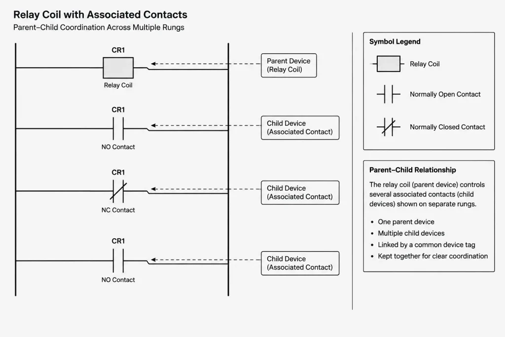
Contacts and their associated coils must share a clear identification system. A coil tag should lead the reader to every related contact, and each contact should lead back to the controlling coil or device. Cross-references are especially important when associated elements appear on different sheets.
A practical cross-reference may point to a sheet, zone, rung, or another controlled location identifier. Choose one method for the drawing set and apply it consistently. If references are generated or updated through a CAD workflow, verify the published output after revisions rather than assuming every reference changed correctly.
| Drawing item | Recommended coordination check | Common drafting problem |
|---|---|---|
| Coil or output | Confirm tag and related contact list | Contacts carry an older device tag |
| Contact | Confirm state symbol, parent device, and location reference | Contact appears without a traceable controlling device |
| Terminal | Compare with terminal and wiring documentation | Terminal identifier differs between drawings |
| Field device | Compare with plans, schedules, and equipment tags | Functional label does not match the project device name |
| Continuation | Check both ends as a matched pair | Reference points to a deleted or relocated rung |
Show contact state without creating ambiguity
Contact symbols are commonly drawn according to a defined normal or reference condition, but that condition must be clear for the project. A reader should not have to infer whether a contact is shown with equipment stopped, power removed, a process condition absent, or a device mechanically actuated.
Use notes where the reference condition cannot be communicated reliably by the standard project symbol. For devices with multiple operating modes, mechanical relationships, or process-dependent states, coordinate the graphic with the written sequence of operation.
Avoid changing a contact symbol merely to make the expected current path look visually closed during normal operation. The symbol must represent the documented contact form and reference condition, not a preferred visual appearance.
Use layers to separate meaning, not fragment the drawing
A ladder diagram usually benefits from a compact layer structure. Possible categories include control conductors, symbols, device tags, wire or terminal identifiers, cross-references, notes, and revision graphics. Keep essential logic visible together in normal plotting conditions.
Do not place critical tags or branches on temporary coordination layers that may be frozen before issue. Likewise, avoid assigning each device type to a separate layer unless that separation supports a real editing or publishing need. Excessive layer subdivision can make schematic maintenance harder without improving the plotted drawing.
Plan for continuations and multi-sheet diagrams
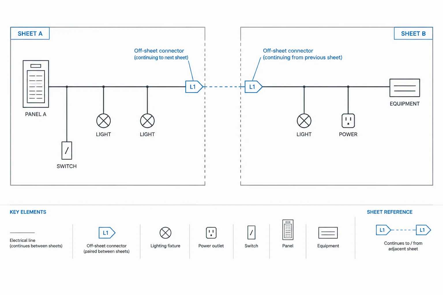
Long control schemes often extend across several sheets. Divide them by function, equipment group, operating sequence, or another documented project structure. Arbitrary sheet breaks can separate a coil from its associated contacts and make review unnecessarily difficult.
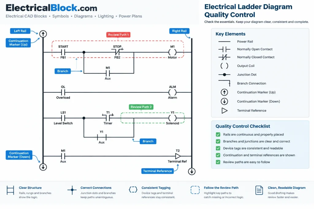
Every continuation should provide enough information to find the matching endpoint. Use paired identifiers and confirm that both ends remain valid after sheets are added, removed, or reordered. If a signal leaves the ladder diagram for another drawing type, identify that destination explicitly instead of using a vague off-sheet arrow.
Add notes that explain exceptions
Graphic logic should carry most of the meaning, but concise notes are valuable for unusual states, external control dependencies, adjustable functions, or interfaces documented elsewhere. Place a note near the affected rung when it applies only to that logic. Reserve general notes for instructions that truly apply throughout the drawing or set.
Do not use a general note to conceal an unresolved design decision. Placeholders, pending selections, and incomplete interfaces should be identified through the project’s issue-control process so they cannot be mistaken for finalized information.
Quality-control workflow for ladder diagram CAD
Review the diagram in logical passes rather than trying to check everything at once:
- Structure pass: Verify rails, rung order, sheet divisions, and continuation references.
- Logic pass: Read each rung as an operational statement and compare it with the intended sequence.
- Symbol pass: Check contact forms, coils, branches, junctions, and output symbols.
- Tag pass: Confirm that device identifiers match schedules, layouts, and related drawings.
- Cross-reference pass: Trace associated contacts, coils, terminals, and off-sheet destinations.
- Plot pass: Review the published sheet for line hierarchy, overlapping text, clipped attributes, and unreadable references.
- Revision pass: Confirm that deleted logic did not leave orphaned tags, contacts, notes, or continuation markers.
A particularly effective review method is to trace one device through the complete documentation chain. Start at its ladder symbol, find every associated contact, locate its terminal or wiring references, and compare its identifier with the physical layout or equipment documentation. This reveals coordination errors that may not be visible when each sheet is reviewed separately.
A diagram should remain editable and understandable
A well-drafted electrical ladder diagram is both a logic document and a coordination tool. Consistent rails, readable rungs, controlled symbols, stable tags, and verified cross-references allow future users to understand how the control concept was documented.
Before using any CAD block or example in a real project, verify its symbol convention, tag structure, reference condition, and compatibility with the project’s requirements. A clean graphic is valuable, but documented design intent and drawing-set consistency are what make the diagram dependable.
Practical handoff checklist for ladder diagram files
Before handing a ladder diagram to another drafter, designer, or reviewer, check more than its plotted appearance. The CAD file should remain understandable and maintainable when its symbols, attributes, and references are edited later.
- Confirm block behavior: Check that symbols retain their intended insertion points, orientation, attributes, and connection alignment.
- Trace parent-child relationships: Make sure every associated contact can be traced to its controlling coil or device and that the reverse path is equally clear.
- Review reference context: A cross-reference should identify a controlled drawing location, not merely point toward a general area.
- Inspect continuation pairs: Verify that outgoing and incoming references agree and that neither endpoint has been deleted or moved without an update.
- Compare related documents: Check device names and tags against available schedules, terminal documentation, wiring drawings, equipment layouts, and sequence descriptions.
- Test the plotted result: Confirm that linework, junctions, attributes, notes, and revision graphics remain legible under the intended publishing settings.
- Remove drafting residue: Look for abandoned symbols, duplicate tags, unused attributes, temporary notes, and geometry left behind by revisions.
How to evaluate rung clarity
A useful review question is whether a reader can describe the purpose of a rung without first searching through unrelated sheets. The operating conditions, alternate paths, interlocks, output, and external references should form a coherent statement. If the explanation depends on hidden layers, unexplained abbreviations, or uncertain contact states, the documentation needs further coordination.
Clarity does not require placing every related detail on the same rung. It requires showing where the remaining information can be found and maintaining consistent identifiers across the drawing set. This distinction helps prevent overcrowded diagrams while preserving traceability.
Frequently asked questions
What is the main purpose of an electrical ladder diagram?
Its primary purpose is to communicate control logic. It shows how contacts and other conditions relate to coils, pilot devices, solenoids, or other outputs within an organized rung structure.
Is a ladder diagram the same as a wiring diagram?
No. A ladder diagram emphasizes functional logic, while a wiring diagram generally emphasizes conductors, terminals, and point-to-point connections. The documents may share device identifiers, but they serve different drafting purposes.
Why are contact and coil cross-references important?
Cross-references let a reader locate every contact associated with a device and return from that contact to the controlling coil or parent device. They are particularly useful when related elements appear in different drawing locations.
Should every CAD symbol contain attributes?
Not necessarily. Attributes are useful when they support consistent tags, terminal identifiers, descriptions, or references. They should be included deliberately and checked for visibility, placement, duplication, and association with the correct symbol.
How should contact state be documented?
Use the symbol convention and reference condition established for the project. When the condition cannot be communicated clearly through the symbol alone, add a concise note and coordinate it with the sequence description.
What should be checked after revising a rung?
Review the logic, device tags, related contacts, terminal information, continuations, off-sheet references, notes, and published output. A small logic change can affect documentation beyond the edited rung.
Leave a Reply
You must be logged in to post a comment.