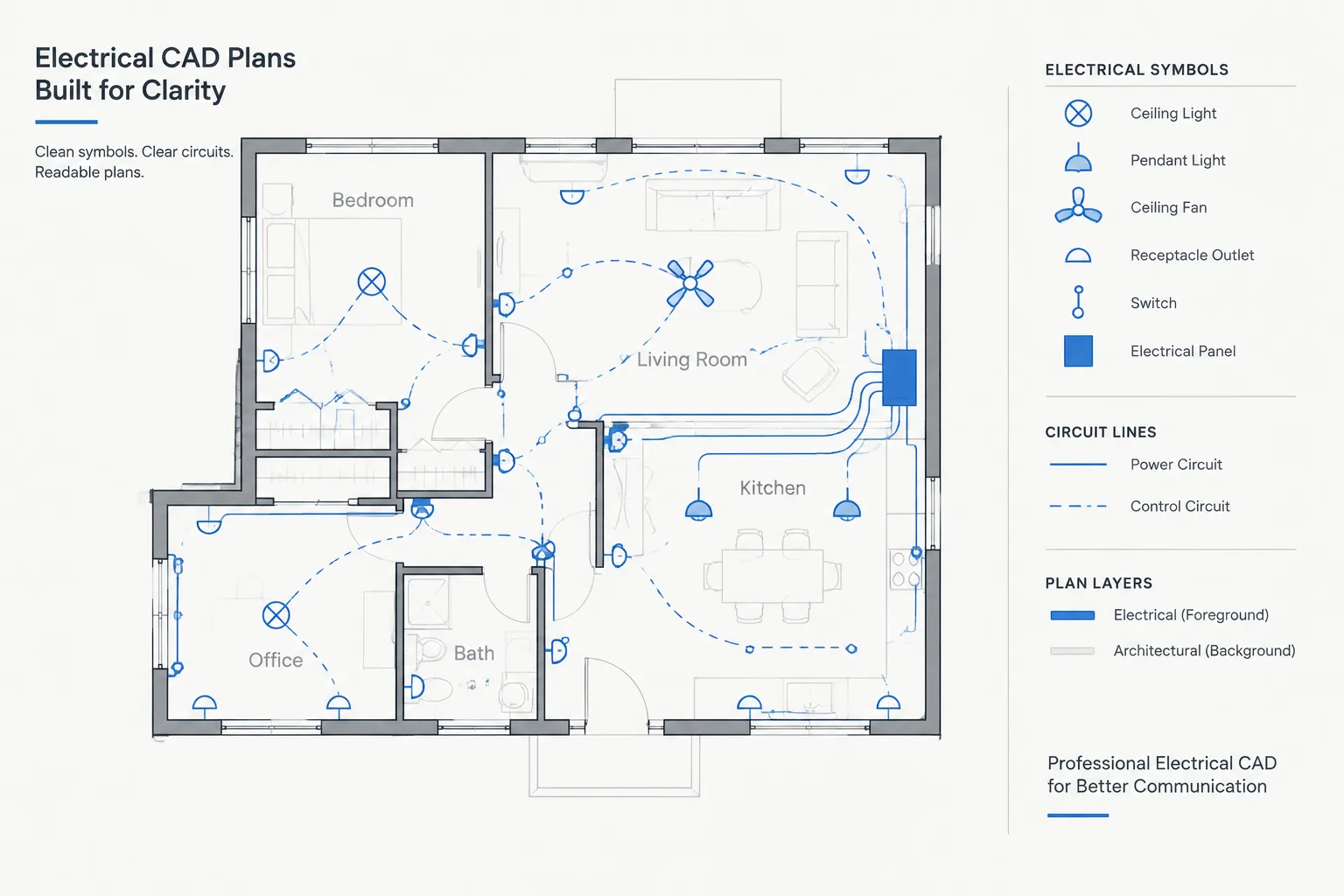
Readable electrical plans depend on more than correct symbols and layers. The visual relationship among referenced backgrounds, design graphics, fills, and annotation determines what a reviewer notices first and what may be overlooked.
This guide explains how electrical CAD draw order, background screening, and masks can be managed as a coordinated documentation system. The objective is not merely to make a sheet look cleaner, but to preserve the architectural context and electrical relationships needed to interpret the plan accurately.
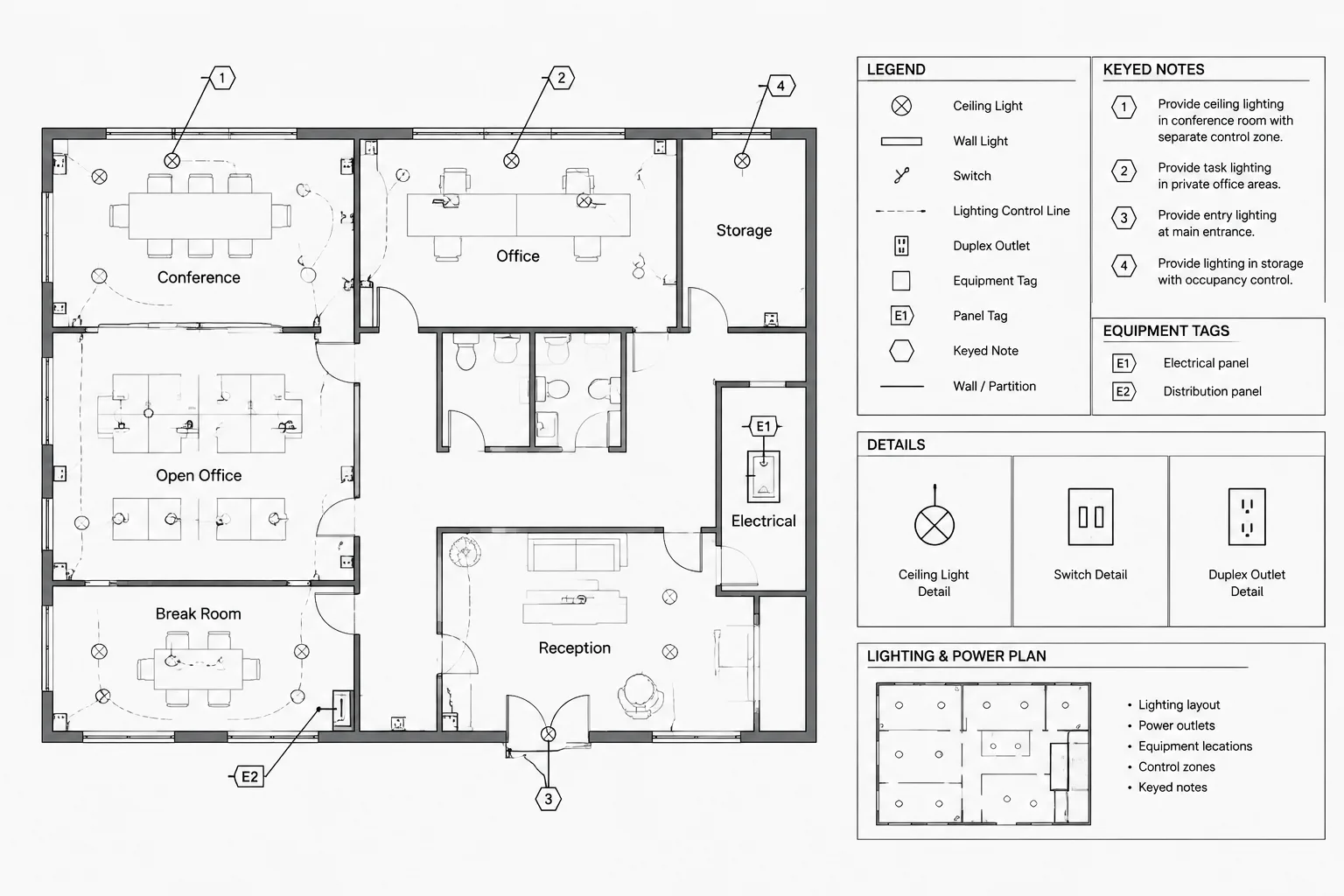
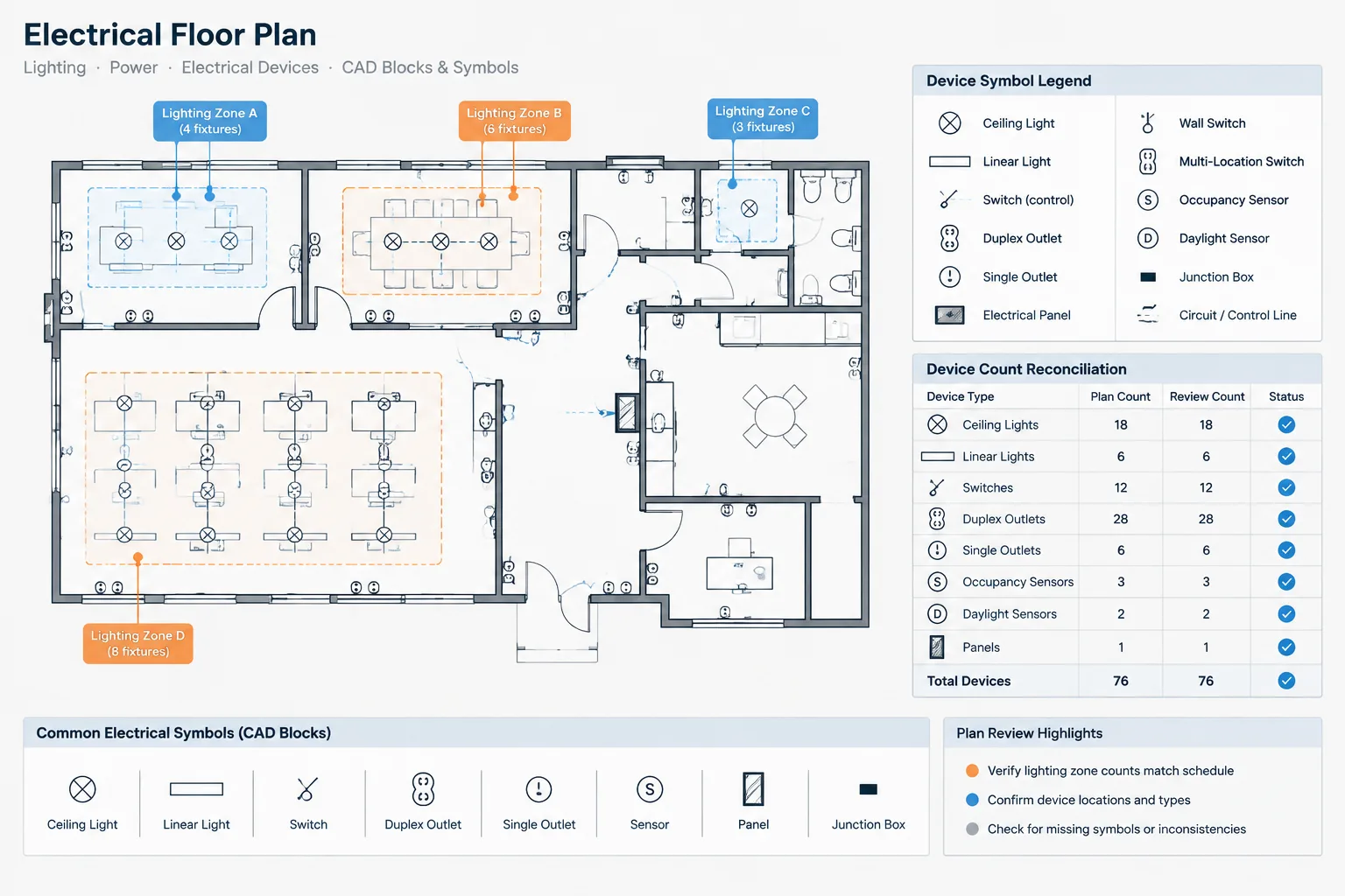
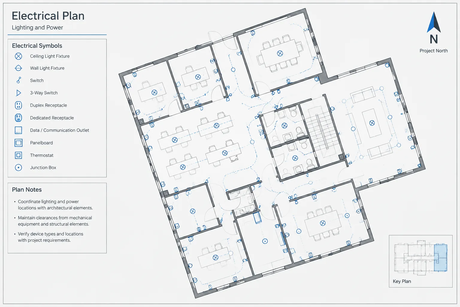
Electrical plans often contain several kinds of information in the same view: architectural walls, ceilings, equipment, electrical symbols, circuiting, tags, notes, match lines, and revision graphics. Even when every object is on the correct layer, the drawing can still be difficult to read if those objects compete visually or overlap in the wrong order.
Draw order, background screening, and masking are therefore more than cosmetic CAD settings. They determine whether the electrical design remains visible over the project background and whether reviewers can understand the sheet without guessing what has been hidden. A reliable workflow uses these tools selectively, preserves coordination information, and verifies the final plotted output.
What Draw Order Controls
Draw order determines which objects appear in front of or behind other objects occupying the same area. It does not change the actual design relationship between them. A receptacle symbol placed over a wall remains in the same location whether the wall line is displayed above or below it, but the selected order can make the symbol either clear or nearly invisible.
Common electrical drawing elements that may require deliberate ordering include:
- Architectural, structural, and reflected ceiling plan backgrounds
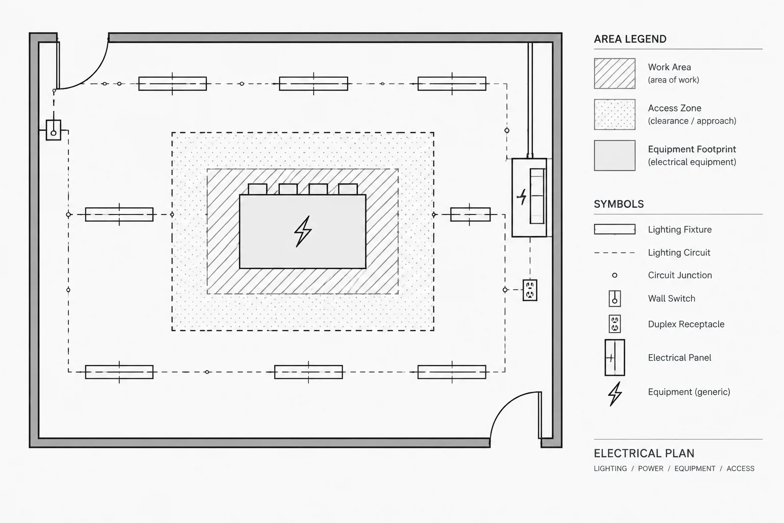
- Electrical equipment footprints and clearance graphics
- Lighting fixtures, devices, and connection symbols
- Circuit lines, home runs, and control relationships
- Room fills, demolition hatches, and renovation boundaries
- Text, tags, leaders, keynotes, and cross-reference bubbles
- Masking objects used behind annotations
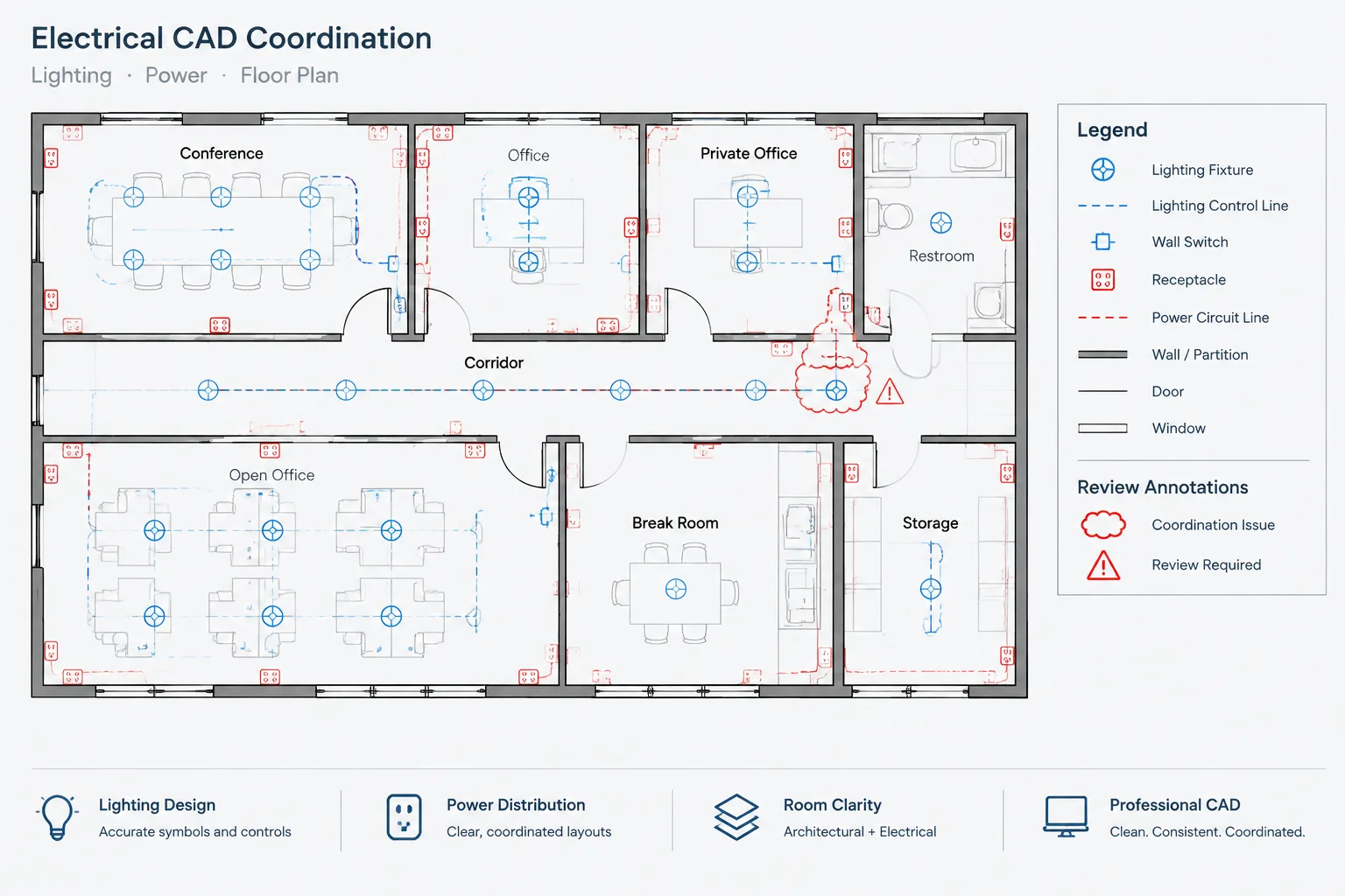
- Revision clouds and other issue-specific markup
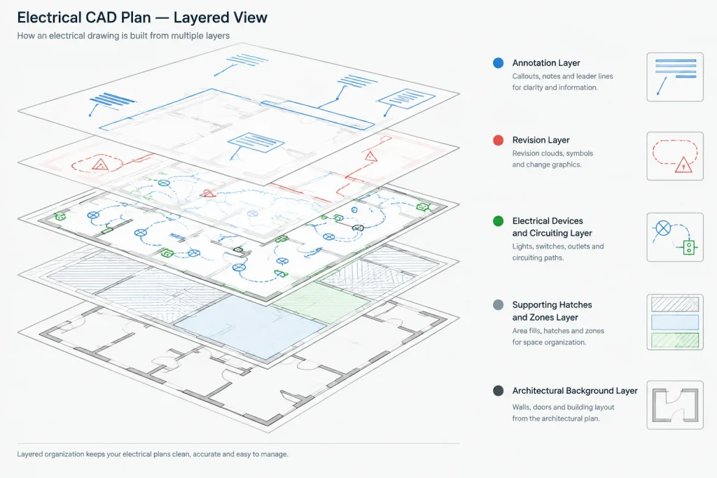
A useful principle is to place reference information behind design information and design information behind critical annotation. This creates a visual hierarchy without requiring every foreground object to use a heavier lineweight.
A Practical Display Hierarchy
The exact layer structure will vary by office and project, but the following hierarchy provides a practical starting point. It should be treated as a drafting framework rather than a universal standard.
| Display level | Typical content | Drafting purpose |
|---|---|---|
| Background | Walls, doors, furniture, ceilings, structural grids, and consultant references | Provides spatial context without dominating the electrical work |
| Supporting electrical graphics | Coverage boundaries, zones, routing guides, hatches, and secondary connection lines | Explains relationships while remaining subordinate to primary symbols |
| Primary electrical content | Fixtures, receptacles, equipment, panels, devices, and major routing | Communicates the designed electrical scope |
| Annotation | Tags, circuit identifiers, notes, leaders, dimensions, and detail references | Identifies and explains the design content |
| Issue graphics | Revision clouds, delta markers, and temporary review markup | Calls attention to changes or review items |
Objects do not need to follow this order in every situation. For example, an architectural room name may need to remain readable if it is the only dependable location reference. The important goal is to establish a repeatable default and document intentional exceptions.
Screening the Background Without Losing Context
Background screening reduces the visual intensity of referenced geometry so that electrical information becomes easier to distinguish. Screening may be controlled through layer plotting properties, reference display settings, color-to-plot relationships, or another office-approved method. The result should be evaluated in the issued output, not only on the CAD screen.
A background is useful only when it remains legible enough to support coordination. Excessive screening can make doors, walls, room boundaries, equipment, ceiling grids, or structural elements disappear from a PDF or print. Insufficient screening can cause the background to compete with circuiting and electrical symbols.
Information that commonly needs to remain visible
- Room limits and circulation paths needed to locate devices
- Door swings that affect device placement or access
- Ceiling grids and ceiling-mounted elements relevant to lighting coordination
- Fixed casework and major equipment affecting outlet locations
- Structural grids, columns, shafts, and major openings
- Room names or numbers used by notes, schedules, or review comments
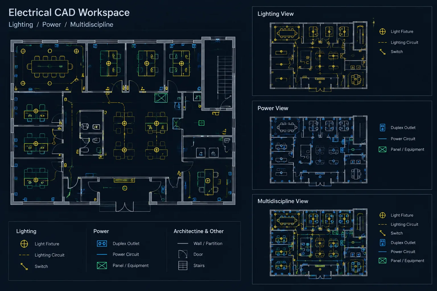
Do not assume that one screening treatment is appropriate for every plan. A lighting plan may need a clearer ceiling background, while a power plan may depend more heavily on furniture, casework, and equipment information. Plan-specific visibility can be managed without duplicating the underlying geometry when layer and reference controls are organized carefully.
When to Use an Annotation Mask
An annotation mask creates a quiet area behind text or a symbol by obscuring selected geometry beneath it. It can be useful where circuit lines, hatches, grids, or detailed backgrounds make an important label difficult to read.
Good candidates for limited masking include:
- Equipment tags over dense equipment outlines
- Circuit identifiers located near several crossing lines
- Detail and section references placed over hatches
- Keynote symbols in congested renovation areas
- Short labels that cannot be moved without breaking their association
Moving the annotation should generally be considered before masking. A small offset and a clear leader often communicate more honestly than a large mask. If a mask is needed, it should be only large enough to protect the annotation and should not erase more context than necessary.
Risks of Overusing Masks and Wipeouts
Masks can conceal coordination problems as effectively as they conceal unwanted linework. A large opaque region behind a panel tag might hide a wall, a door swing, another device, or part of a clearance boundary. Because the hidden objects still exist in the model, the CAD file may appear correct when objects are selected individually even though the plotted sheet is incomplete.
Common masking failures include:
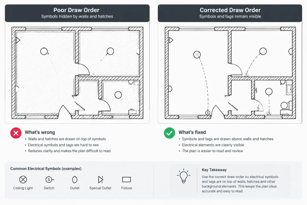
- A mask hiding part of an adjacent electrical symbol
- A block containing an oversized internal mask
- A mask boundary becoming visible in the plotted file
- A solid fill covering text because its draw order changed
- A mask that works in one view but obscures information in another
- Nested blocks and references producing unexpected display results
- A background update introducing new geometry beneath an old mask
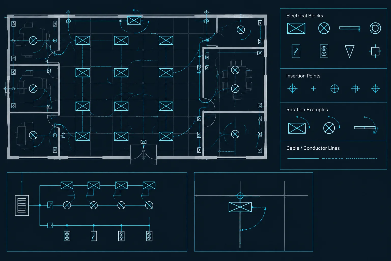
Reusable symbols deserve special attention. A mask built into a CAD block may behave acceptably on a simple background but hide important geometry when inserted near a wall intersection, equipment outline, or ceiling element. The block should be tested in realistic drawing conditions rather than reviewed only in isolation.
Handling Hatches, Fills, and Renovation Graphics
Hatches and fills can communicate demolition limits, work areas, floor regions, equipment zones, or other drawing conditions. They can also overwhelm symbols and annotation if placed too high in the display stack.
As a general drafting approach, area graphics should sit behind the objects they describe. Their pattern, density, and plotted appearance should allow linework and labels to remain recognizable. If a hatch must identify a small or congested area, consider using a clear boundary with a keyed note rather than relying entirely on a visually dominant pattern.
Existing-work or demolition graphics should also be reviewed against the background. Similar line patterns can merge and create an unintended dark region. Plot testing is especially important when multiple disciplines use hatching in the same location.
A Repeatable Draw-Order Workflow
1. Stabilize the references
Confirm that the current architectural and consultant references are loaded, aligned, and displaying the intended layers. Draw-order corrections made against an incomplete background may fail when the complete reference set is restored.
2. Establish broad object groups
Organize the view into background, supporting graphics, primary electrical content, annotation, and issue graphics. Correct group-level conflicts before adjusting individual objects.
3. Resolve overlaps by importance
Determine which object carries the more important message. Preserve required design and coordination information rather than automatically bringing every electrical object to the front.

4. Reposition before masking
Move tags, adjust leaders, or simplify unnecessary crossing lines where practical. Use masks only when relocation would reduce clarity or disconnect the annotation from its subject.
5. Inspect reusable blocks
Check whether symbols contain fills, hidden boundaries, or masking objects. A problem attributed to the plan may actually be embedded within a block definition.
6. Plot through the intended output process
Review the sheet as a PDF or other project deliverable. Check both normal viewing and enlarged areas. CAD display quality does not guarantee that transparency, screening, fills, or masks will reproduce as expected.
7. Recheck after background updates
Architectural changes can place new walls, labels, equipment, or ceiling geometry behind existing masks. Include overlap review in the normal reference-update and quality-control process.
Quality-Control Questions
- Can primary electrical symbols be distinguished from the background?
- Are room boundaries, doors, grids, and relevant equipment still readable?
- Do tags and notes obscure the objects they are intended to identify?
- Are circuit lines hidden by fills, blocks, or referenced geometry?
- Do masks conceal nearby devices, routing, or access information?
- Are hatch boundaries and mask frames absent from the final output unless intentionally shown?
- Do revision graphics remain visible without covering the revised work?
- Does the PDF match the visual hierarchy expected from the CAD view?
Preserve Meaning, Not Just a Clean Appearance
A clean electrical plan is not simply a drawing with fewer visible lines. It is a drawing in which the background, design content, and annotation remain understandable together. Draw order should clarify the document rather than conceal conflicts, and screening should reduce visual competition without removing necessary context.
By using a consistent hierarchy, limiting masks, testing reusable blocks, and reviewing actual plotted output, CAD teams can improve readability while preserving the coordination value of the drawing. Every downloaded symbol or office library block should still be inspected and adapted to the project’s documentation requirements before use.
Choosing the Right Visibility Control
Several CAD tools can make overlapping graphics easier to read, but they do not solve the same problem. Selecting the appropriate control helps prevent temporary display fixes from becoming hidden documentation issues.
- Draw order changes which overlapping object appears in front. It is most useful when both objects should remain present but one must have visual priority.
- Background screening reduces the visual strength of contextual information while keeping that information available for coordination.
- Layer or reference visibility determines whether an entire category of information belongs in the view. It is generally more appropriate than masking when content is unnecessary for that plan.
- Annotation masking clears a limited area behind a label or symbol. It should be treated as a local readability tool rather than a general cleanup method.
- Clipping limits the displayed extent of a reference or view. It can reduce unrelated background content but should not remove context needed to understand the electrical scope.
Diagnosing Common Output Problems
When the CAD view and issued output do not match, review the display system methodically instead of repeatedly sending objects to the front.
- Electrical symbols appear weak: compare their plotted appearance with the background and confirm that screening is being applied through the intended output configuration.
- Text disappears over fills: inspect the fill, text, and any surrounding block definitions for conflicting draw order or embedded masking.
- Unexpected blank areas appear: look for masks or wipeout-style objects inside blocks, nested references, and annotation components.
- A hatch covers circuiting: verify that the area graphic is behind the circuit lines and that its output appearance is not visually overpowering them.
- Reference information becomes unreadable: determine whether screening, layer visibility, clipping, or the output process removed information needed for orientation.
- Results vary between views: compare view-specific overrides, reference settings, layer states, and reusable block behavior.
Review Readability from More Than One Perspective
The person drafting a plan already knows what the drawing is intended to show, so missing or obscured information may be mentally reconstructed without being noticed. A useful quality review asks whether someone unfamiliar with the view can locate devices, follow circuit relationships, identify referenced equipment, and understand the associated notes without relying on assumptions.
Readability review should also distinguish a crowded but complete plan from a visually clean but incomplete one. If simplifying the display removes a wall intersection, door relationship, equipment outline, or electrical connection needed to understand the work, the result has lost meaning rather than gained clarity.
Frequently Asked Questions
Is draw order the same as layer order?
No. Layers organize and control categories of objects, while draw order controls which overlapping objects display in front. Objects on properly assigned layers can still require draw-order review.
Should all electrical symbols be brought to the front?
Not automatically. Primary symbols should be easy to identify, but bringing every electrical object forward can cover annotations, coordination boundaries, or other information. The priority should follow the message each object communicates.
When is screening better than turning off a background layer?
Screening is useful when the background information remains necessary for location and coordination but should not compete with the electrical design. Turning a layer off is more appropriate when its content is not needed in that view.
Why can a mask work in one location but fail elsewhere?
The surrounding geometry changes. A mask that clears harmless linework in one area may conceal a device, wall, boundary, or label in another. Masks embedded in reusable blocks require particular attention because their effect depends on where each block is placed.
Why does the PDF look different from the CAD view?
The output process may handle screening, transparency, fills, references, and masking differently from the working display. Layer properties and output settings can also affect the result. The deliverable itself should therefore be part of the readability review.
Can masking replace better annotation placement?
Usually not. Repositioning a tag, refining a leader, or reducing unnecessary crossings often produces a clearer result. Masking is most effective when used locally and only after those options have been considered.
Leave a Reply
You must be logged in to post a comment.