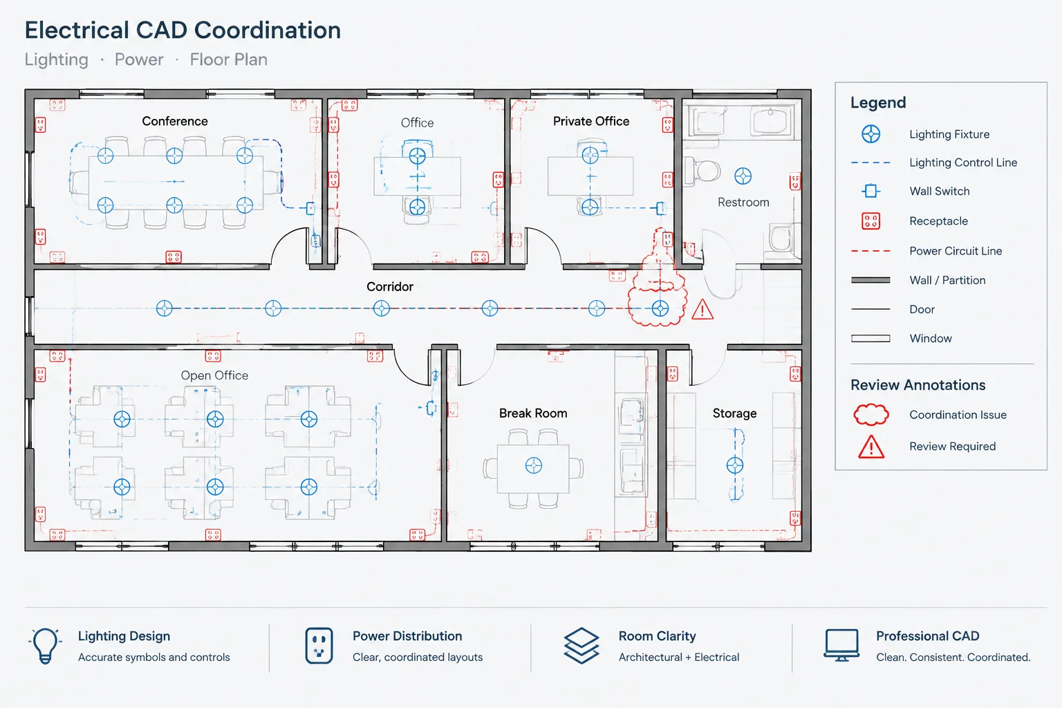
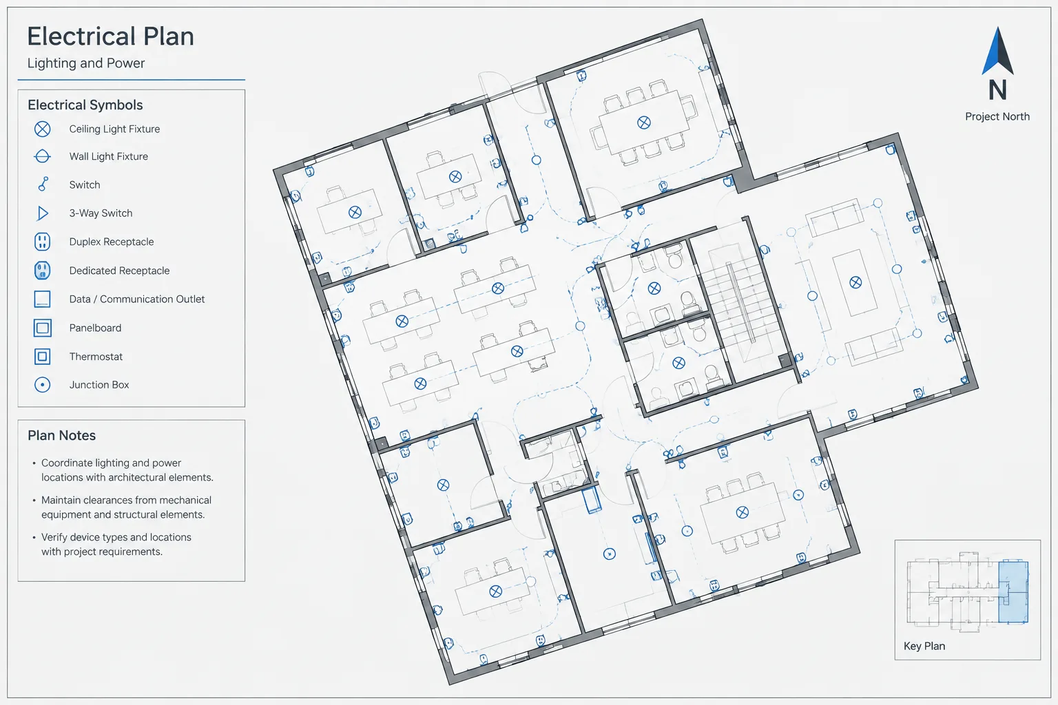
Electrical CAD room coordination connects architectural space information with device locations, circuit descriptions, control areas, schedules, and dependent diagrams. The goal is not merely to display room tags, but to ensure that every electrical reference uses the correct space designation and communicates the intended relationship.
This guide outlines a drawing-focused workflow for controlling room information, reviewing architectural revisions, and finding mismatches before an electrical set is issued.
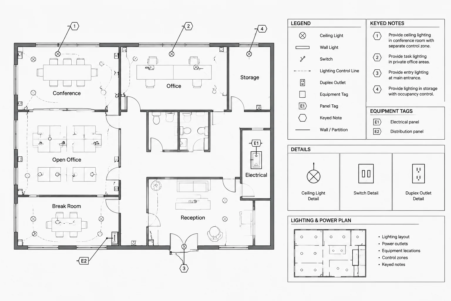
Room names and numbers are easy to treat as background information, but they often become working references throughout an electrical drawing set. Designers use them to identify device locations, organize panel schedule descriptions, define lighting control areas, write equipment connection notes, and communicate with other disciplines.
When architectural room data changes, electrical documentation can become inconsistent even if the device geometry remains correct. A floor plan might show a revised room number while a panel schedule, lighting control diagram, or equipment schedule still carries the earlier designation. A deliberate electrical CAD room coordination workflow helps prevent these mismatches.
Why room references matter in electrical drawings
A room reference usually combines a room number, a room name, or both. The architectural floor plan is commonly the primary source, but the information can appear in many electrical documents:
- Lighting and receptacle plans
- Equipment connection plans and schedules
- Panel schedule circuit descriptions
- Lighting control diagrams and zone schedules
- Fire alarm, communications, and security plans
- Enlarged plans, details, and interior elevations
- Testing, commissioning, and closeout documents
Room information does more than describe geography. It gives reviewers a shared language for finding devices and understanding design intent. This makes consistency more important than the visual appearance of any single room tag.
Use the architectural background as the location source
Electrical drafters should generally avoid rebuilding architectural room tags as independent electrical text unless there is a clear documentation reason. Manually copied labels can remain in place after the architectural source changes, creating two competing versions of the room data.
A coordinated architectural background should provide the basic room boundaries, names, and numbers needed for the electrical plan. Electrical annotations can then reference that information without duplicating it unnecessarily.
Control background visibility
Architectural room tags must be visible enough to support electrical plan reading but should not compete with electrical symbols and circuiting. Consider how the background will appear in the final plotted sheet, not only how it looks on screen.

Depending on the project workflow, room-related background graphics may be controlled through referenced-file layers, visibility settings, display overrides, or a separate prepared background. The method is less important than achieving a predictable result across every applicable electrical sheet.
Do not rely on position alone
A room tag near a device does not always prove that the device belongs to that room. Open plans, shared walls, ceiling-mounted equipment, alcoves, and devices serving adjacent spaces can make proximity misleading. Where the association affects a schedule or diagram, confirm it against room boundaries and the design intent.
Build a room-reference hierarchy
Before coordinating the drawings, decide which document governs each type of information. A simple hierarchy reduces uncertainty during revisions.
| Information | Typical controlling source | Electrical coordination use |
|---|---|---|
| Room number and name | Current architectural plan or room data | Plan identification and schedule descriptions |
| Electrical device location | Electrical floor plan | Installation intent and circuit association |
| Equipment designation | Coordinated equipment schedule or project naming system | Tags, feeders, connections, and diagrams |
| Circuit description | Electrical panel schedule coordinated with the plan | Load identification and plan-to-schedule checking |
| Control area name | Lighting control documentation coordinated with room layout | Zone labels, devices, and control diagrams |
The room number may originate with the architect, but an electrical circuit designation should still be controlled within the electrical documents. Coordination does not mean allowing background text to replace electrical design data.
Separate room data from electrical annotations
Good CAD organization makes changes easier to track. Architectural room tags, electrical device tags, circuit annotations, and schedule text should remain distinguishable by ownership and function.
Avoid placing copied room names on the same layer as circuit numbers or general electrical notes. If supplemental room references are required on an electrical sheet, place them on a clearly identified electrical annotation layer and document why they exist. This allows drafters to isolate, review, and update them without disturbing other text.
Consistent text style and plotting hierarchy are also useful. Architectural room data can be subdued while electrical tags remain prominent. The objective is not to hide the room information but to make the electrical scope visually dominant.
Coordinate room references across plan types
A single space may appear differently on lighting, power, communications, and life-safety plans. Each discipline plan should use the same underlying room identification even when its electrical content differs.
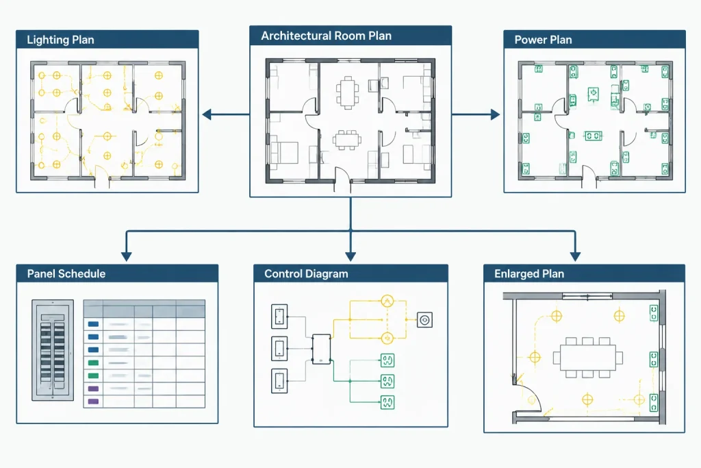
Lighting plans
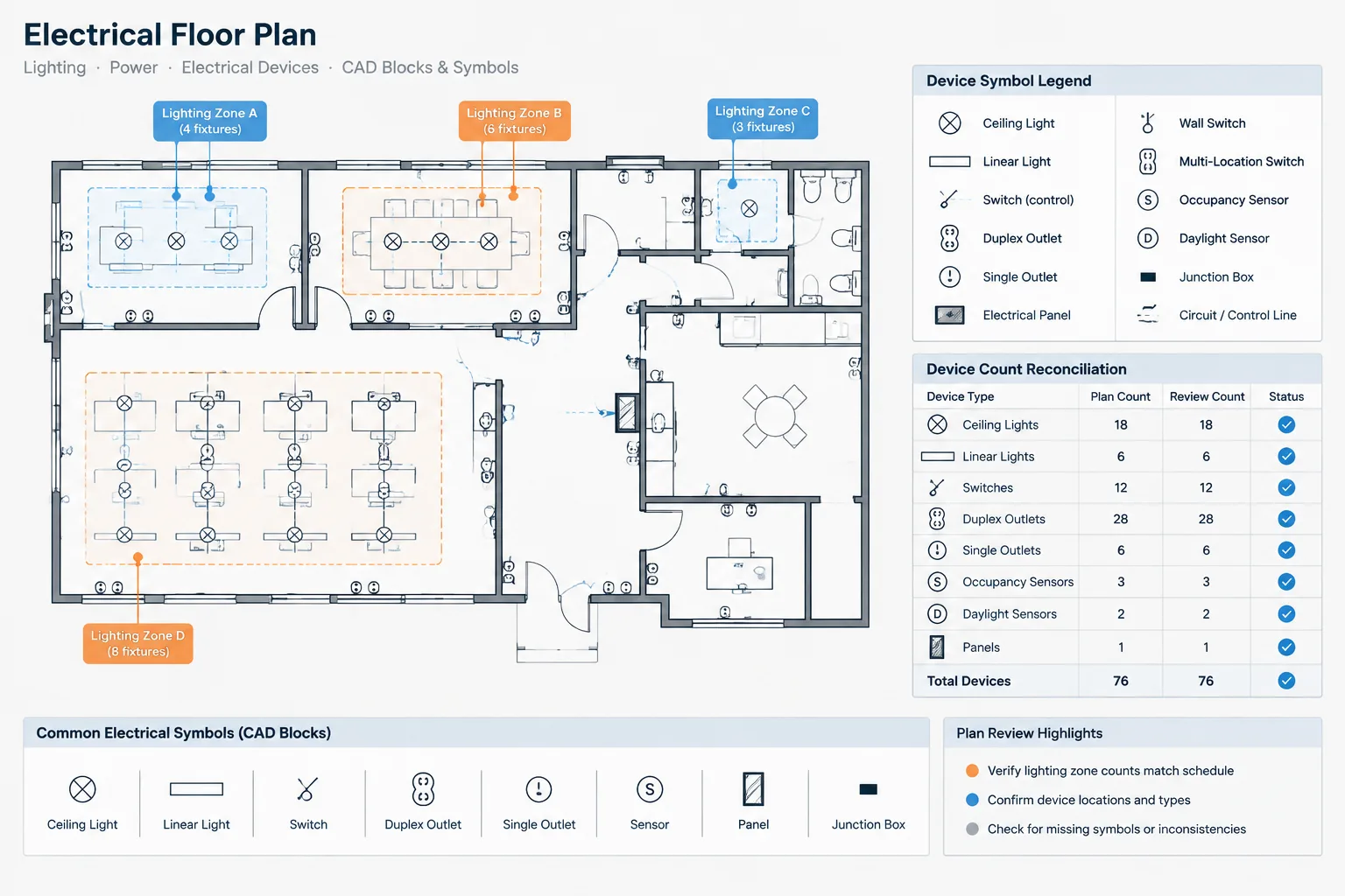
Room changes may affect fixture grouping, control zones, sensor associations, switching notes, and lighting schedule remarks. A renamed room can also change how a control area should be described, even if the fixture layout remains unchanged.
Power plans
Check receptacles, dedicated outlets, equipment connections, circuit home runs, and panel schedule descriptions. Generic descriptions may be insufficient when several rooms contain similar equipment, while excessively detailed descriptions can become fragile when layouts change.
Systems plans
Fire alarm, security, data, and communications devices may use room names in risers, point lists, sequence documents, or device schedules. Confirm whether each reference describes the physical device location, the area served, or both. Those concepts are not always identical.
Enlarged plans and details
An enlarged plan should agree with the parent floor plan. Use a consistent room number and confirm that callouts direct readers to the correct enlarged area. If a room is divided or renumbered, both views must be reviewed rather than assuming the reference will update automatically.
Handle room renumbering as a drawing-wide change
Room renumbering should not be treated as a simple background replacement. It is a coordination event that may affect annotations outside the floor plan.
When updated architectural information is received, use a structured review:
- Identify added, removed, divided, combined, renamed, and renumbered rooms.
- Compare room boundaries as well as room tags.
- Search electrical text and schedules for superseded names or numbers.
- Review panel schedule descriptions associated with affected spaces.
- Check lighting control zone names and diagram references.
- Review enlarged plans, details, and sheet callouts.
- Confirm equipment tags whose identifiers include location information.
- Record unresolved changes for design review rather than guessing.
A text search can help find repeated room references, but it cannot detect every problem. Abbreviations, shortened schedule descriptions, and graphical associations require visual review.
Avoid embedding unstable room data in permanent identifiers
Some projects include room numbers within equipment tags, circuit descriptions, control zone names, or device identifiers. This can improve location recognition, but it also creates additional work whenever rooms are renumbered.
Before adopting location-based identifiers, consider whether the room designation is expected to remain stable and whether the identifier must persist through construction, operations, or future renovations. A durable equipment tag and a separate location field may be easier to maintain than an identifier that must change whenever the architectural plan changes.
If a project already uses room-based identifiers, apply the convention consistently and maintain a clear record of changes. Do not partially update the system.
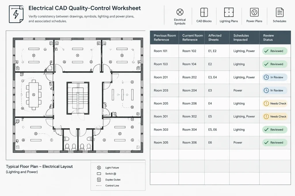
Use a room coordination worksheet
For larger or frequently revised projects, a simple room coordination worksheet can provide a useful bridge between architectural changes and electrical documents. It does not need to replace the formal drawing schedules.
| Tracking field | Purpose |
|---|---|
| Previous room reference | Finds existing electrical notes and schedule entries |
| Current room reference | Establishes the coordinated designation |
| Change type | Distinguishes renaming, renumbering, division, or combination |
| Affected electrical sheets | Defines the review scope |
| Affected schedules or diagrams | Captures non-plan references |
| Review status | Shows whether coordination is complete or unresolved |
This worksheet is especially helpful when different team members maintain plans, schedules, and diagrams. It gives the team a common change list without making the CAD background itself the only communication tool.
Final quality-control checks
Before issuing the electrical set, review room coordination in the plotted sheet context. Confirm that room tags are legible, current, and not obscured by electrical symbols. Verify that copied room references do not conflict with the architectural background.
- Compare each electrical plan with the latest approved coordination background available to the team.
- Check that room names and numbers agree across related electrical plan types.
- Review schedule descriptions for obsolete references.
- Confirm that control areas and served areas are not mislabeled as device locations.
- Inspect enlarged plans and dependent details separately.
- Remove temporary comparison marks, duplicate labels, and abandoned annotations.
- Document any known discrepancy that cannot be resolved before issue.
Reliable electrical CAD room coordination depends on clear ownership, controlled background use, and a review process that reaches beyond the floor plan. Treating room changes as drawing-set changes produces documents that are easier to navigate, check, revise, and use during later project phases.
Distinguish location, service, and control relationships
A room reference can describe where a device is physically installed, which space it serves, or which control area includes it. These relationships may coincide, but they should not be assumed to mean the same thing.
- Physical location: The room containing the device or equipment symbol.
- Area served: The room or group of spaces supported by the device, circuit, or equipment.
- Control association: The space, zone, or functional area governed by a control device or sequence.
- Schedule description: The wording used to help readers identify a circuit, load, device, or connection.
During coordination, identify which relationship each annotation is intended to communicate. This prevents a panel description based on an area served from being mistaken for the panel’s physical location, or a control-zone label from being treated as a room tag.
Define completion in the project workflow
A room update is complete only when the affected plans, schedules, diagrams, details, and supporting lists have been reviewed. Updating the architectural reference file may correct the visible floor plan while leaving manually entered electrical text unchanged.
A useful closeout check is to compare the current room change record with every document that contains location-dependent information. Each discrepancy should be corrected, intentionally retained with an explanation, or identified for design-team resolution. This creates a traceable coordination decision instead of relying on memory or visual familiarity with the plan.
Preserve review context
Comparison graphics, revision clouds, temporary notes, and marked-up plots can help reviewers understand what changed. Keep these review aids separate from permanent electrical annotations so they can be removed or archived without altering the design documentation.
When responsibility is shared, record who owns the architectural designation, who updates electrical references, and who confirms consistency before issue. Clear ownership is often more effective than adding duplicate room labels throughout the CAD file.
Frequently asked questions
Which document should control room names and numbers?
The current architectural room information established by the project team will usually control space names and numbers. Electrical documents should reference that source while retaining electrical ownership of circuiting, equipment designations, and other discipline-specific data.
Should electrical drafters copy architectural room tags into their plans?
Unnecessary copies should generally be avoided because independent text can become outdated. If supplemental room references are required, place them on a clearly identified electrical annotation layer and include them in revision reviews.
Why is replacing the architectural background not enough?
Room information may also exist in panel schedules, control diagrams, equipment schedules, enlarged plans, callouts, and manually entered notes. Those references may not update when a background file changes.
How should a device serving another room be documented?
Clarify whether the annotation describes the device’s physical location or the area it serves. Use wording and schedule fields that preserve this distinction rather than relying only on the nearest room tag.
Can a CAD text search find every obsolete room reference?
No. Searches are useful for exact or repeated text, but they may miss abbreviations, shortened descriptions, graphical relationships, and references that were never entered as searchable text. Visual and schedule-based reviews remain necessary.
What should be checked after a room is divided or combined?
Review room boundaries, device associations, control areas, circuit descriptions, equipment references, enlarged views, dependent details, and relevant schedules. Confirm the intended relationship rather than assigning devices solely by proximity.
How can teams track room changes across an electrical drawing set?
Use a controlled change record or coordination worksheet that identifies the former designation, current designation, affected documents, review responsibility, and resolution status. This helps separate confirmed changes from unresolved questions.
Leave a Reply
You must be logged in to post a comment.