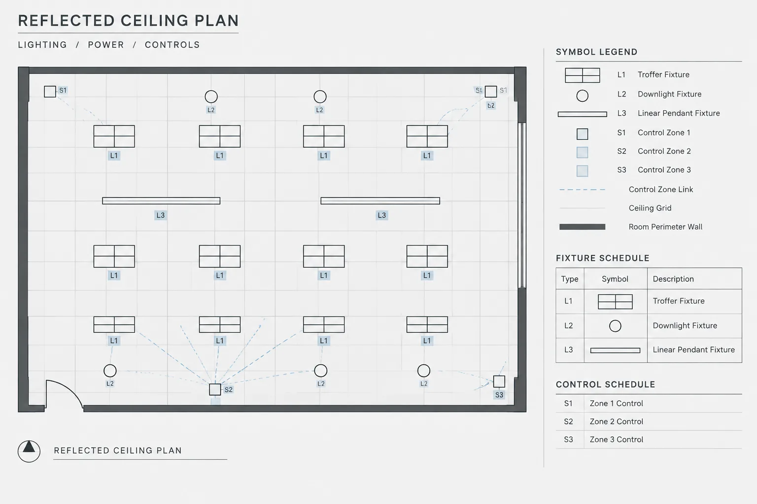
Lighting fixture tags in CAD provide the identification layer that connects plan graphics with fixture schedules, control documentation, mounting information, and related details. Their effectiveness depends not only on how they look, but also on how consistently their values are created, stored, displayed, and revised.
This reference explains how to keep fixture identifiers distinct from circuit and control annotations, manage tags as coordinated drawing data, and review the relationships among lighting plans, schedules, legends, and controls. The emphasis is on drafting clarity and documentation workflow rather than on prescribing a universal tag format.
Lighting fixture tags connect graphic symbols on a plan to the information needed to interpret those symbols. A well-managed tag helps a reader move quickly from a fixture location to its schedule entry, mounting description, control relationship, and related details. A poorly managed tag can create duplicate identifiers, unclear fixture types, and conflicts between plans and schedules.
The goal is not to place as much information as possible beside every fixture. The goal is to create a stable identification system in which each drawing component has a clear purpose. The plan should communicate location and design intent, while schedules, notes, diagrams, and details carry the supporting information.
What a Lighting Fixture Tag Represents
A fixture tag usually identifies a fixture type rather than one individual installed unit. Multiple fixture symbols may therefore share the same tag when they refer to the same scheduled type. Project conventions vary, so the drawing legend or fixture schedule should explain how identifiers are structured.
A fixture tag may coordinate with several kinds of information:
- The fixture type shown in the lighting fixture schedule
- The corresponding plan symbol or graphic family
- Mounting or installation notes
- Emergency, backup, or special operating status
- Control zones, switching references, or control device relationships
- Related architectural ceiling types or mounting conditions
- Details, elevations, or manufacturer data reviewed for the project
These relationships do not mean that every property belongs inside the tag. A compact identifier is usually easier to maintain than a long coded label whose characters attempt to describe every fixture characteristic.
Separate the Fixture Type from Other Identifiers
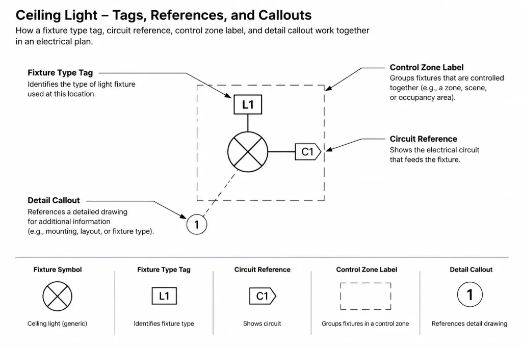
One of the most important drafting decisions is determining which nearby labels are part of the fixture tag and which represent separate systems. A fixture type, circuit reference, control zone, and detail callout may appear near the same symbol, but they answer different questions.
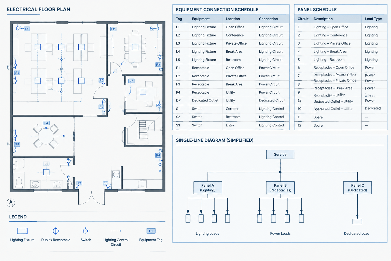
| Identifier | Primary purpose | Typical coordination target |
|---|---|---|
| Fixture type | Identifies the scheduled luminaire type | Lighting fixture schedule |
| Circuit reference | Associates the fixture with documented circuiting | Panel schedule and power distribution documents |
| Control reference | Shows a switch leg, zone, group, or control relationship | Lighting control plan or diagram |
| Emergency or special status | Distinguishes a required operating condition | Legend, schedule, one-line, or control documentation |
| Detail reference | Directs the reader to installation or mounting information | Detail or section sheet |
Keeping these identifiers logically separate improves editing. For example, changing a control zone should not require redefining the fixture type. Likewise, a circuit change should not create a new fixture type unless the actual scheduled fixture definition also changes.
Choose a Consistent Tag Structure
A useful fixture identification system should be concise, expandable, and visually distinct from other plan annotations. Alphabetic, numeric, or combined identifiers can all work when applied consistently. The specific format should follow the project documentation requirements rather than an assumed universal convention.
Before drafting begins, decide how the system will handle:
- Base fixture types and approved project variants
- Fixtures that look similar on plan but differ in schedule information
- Special mounting conditions
- Emergency or alternate-source operation
- Decorative fixtures coordinated with another discipline
- Existing fixtures that remain, are relocated, or are removed
- Future or owner-furnished items
Avoid assigning meaning to capitalization, suffixes, line types, or enclosures unless that meaning is documented in the legend or schedule. An unexplained suffix may be obvious to its creator but ambiguous to reviewers and future editors.
Build Tags as Managed CAD Objects
Lighting fixture tags are easier to coordinate when they are managed independently from the fixture geometry. The exact CAD method depends on the project platform and office workflow, but a tag should generally remain editable without redrawing the fixture symbol.
Use attributes or structured text deliberately
If a block attribute stores the fixture type, use a consistent attribute name and value format across the library. Do not mix plain text, attributes, and manually edited block geometry without a reason. Inconsistent storage makes automated checking and data extraction less reliable.
Keep orientation readable
The fixture symbol may rotate to match a ceiling grid, wall, or architectural feature, while the tag text usually needs to remain readable in the sheet orientation. Treat symbol rotation and tag rotation as separate controls when possible. Mirrored blocks should also be checked to ensure that text does not become reversed or shift to an unintended side.
Control visibility by drawing purpose
A fixture type may need to appear on a lighting plan but not on a separate control plan that uses different annotations. Layers, display states, or view-specific annotation methods can help, but they should not create competing tag values for the same fixture. The underlying identification should remain consistent even when its display changes.
Place Tags for Plan Readability
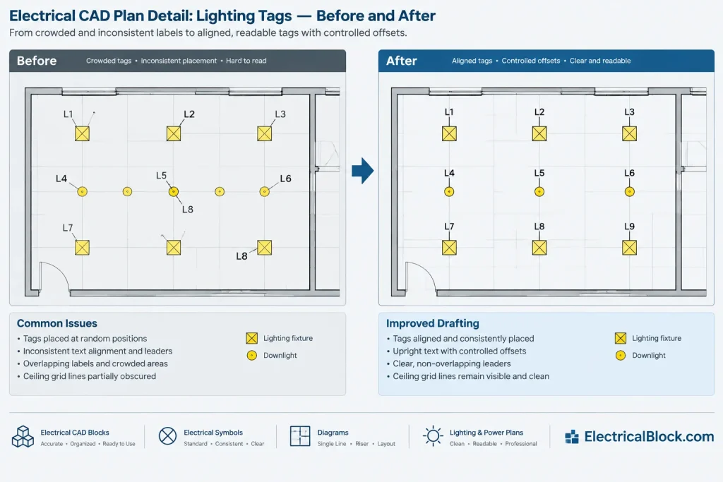
Tag placement should support quick visual association without covering the symbol, ceiling grid, room name, or control linework. Establish a preferred offset and apply it consistently, then adjust only where plan congestion requires it.
Useful placement practices include:
- Place the tag near the fixture it identifies without touching the symbol.
- Use a consistent side or relative position where the background permits.
- Avoid placing unrelated tags between a fixture and its identifier.
- Use leaders only when proximity does not make the association clear.
- Check tags at plotted sheet scale rather than relying only on model-space zoom.
- Review repetitive areas for accidental omissions caused by copied geometry.
In dense reflected ceiling plans, tagging every repeated fixture can overwhelm the drawing. A project may use representative tagging, area notes, or other grouping methods, but the chosen method must make the scope unambiguous. Do not assume that one tagged symbol automatically defines every similar-looking symbol unless the drawing explains that convention.
Coordinate the Plan with the Fixture Schedule
The plan and fixture schedule should be treated as two views of the same information set. Every plan type should resolve to a valid schedule entry or an explicitly documented exception. Conversely, every scheduled type should be reviewed to determine whether it is actually used.
A practical reconciliation sequence is:
- Extract or list the distinct fixture type values used in the plan files.
- Compare those values with the schedule identifiers.
- Find tags that have no matching schedule row.
- Find schedule rows that are not referenced on any applicable plan.
- Check visually similar symbols that carry different type values.
- Review suffixes, spaces, punctuation, and capitalization for accidental variations.
- Confirm that revised fixture types were updated in plans, schedules, legends, and details.
Unused schedule entries are not always errors. They may represent alternates, future work, or types used on another drawing package. Their status should nevertheless be intentional and understandable.
Coordinate Fixture Tags with Lighting Controls
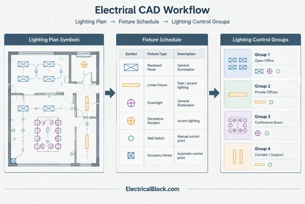
Fixture type and control assignment should not be conflated. Two fixtures of the same scheduled type may belong to different control groups. Likewise, a control zone may contain several fixture types.
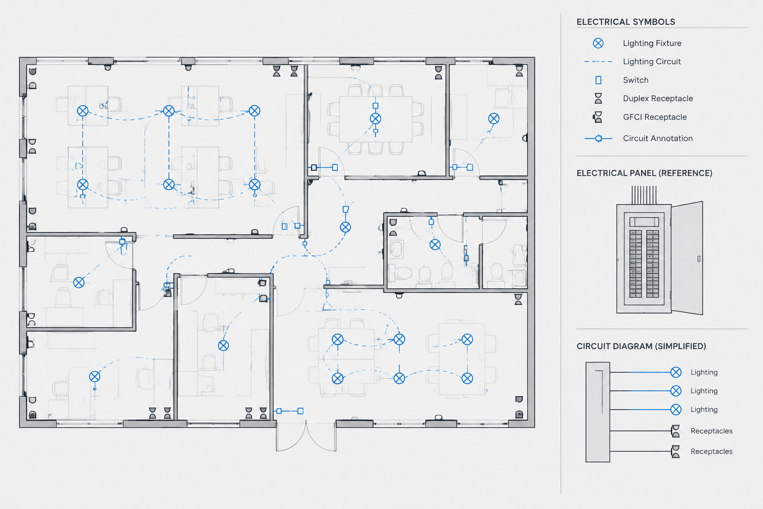
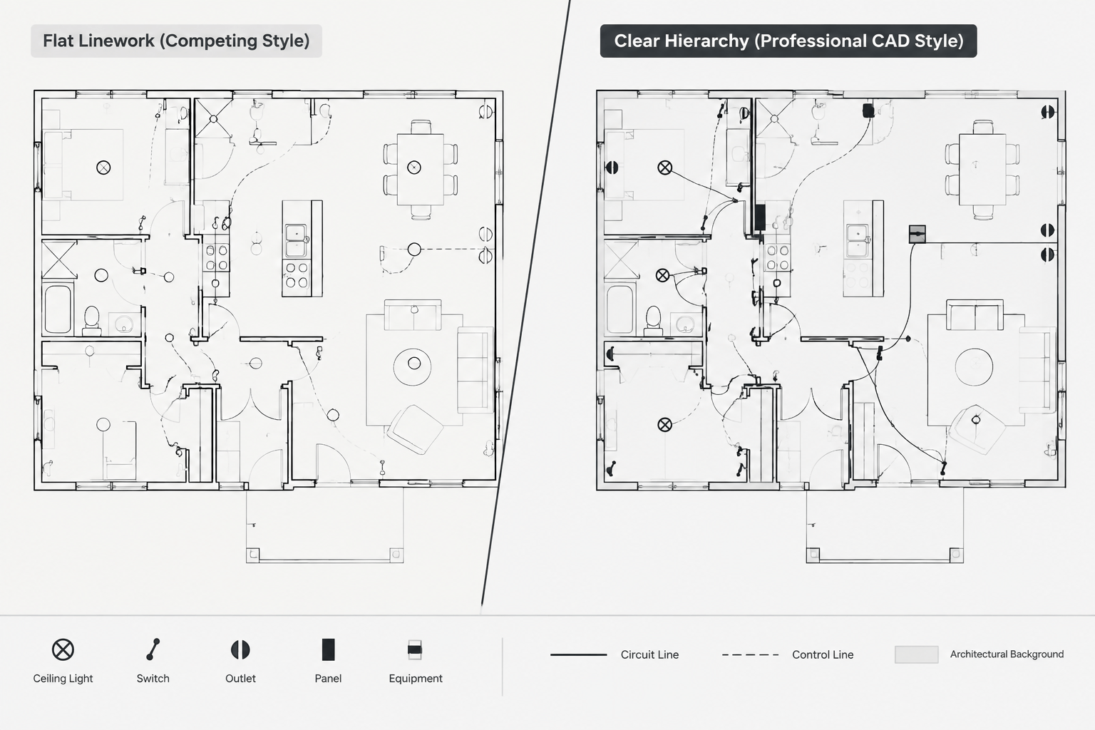
Use distinct graphic conventions for fixture identification and control relationships. Control information may be shown through lines, labels, zone boundaries, device references, or diagrams depending on the project. Whatever method is selected, verify that control graphics do not obscure fixture tags or make a control label look like part of the fixture type.
Where control information is split across drawings, provide enough cross-reference information for a reader to follow the relationship. The lighting plan, control plan, schedule, and sequence documentation should not use contradictory names for the same group.
Handle Revisions Without Losing Tag History
Fixture tags often change during design development, product coordination, or construction documentation. Renaming a type can affect many drawing locations, so revisions should be managed as data changes rather than isolated text edits.
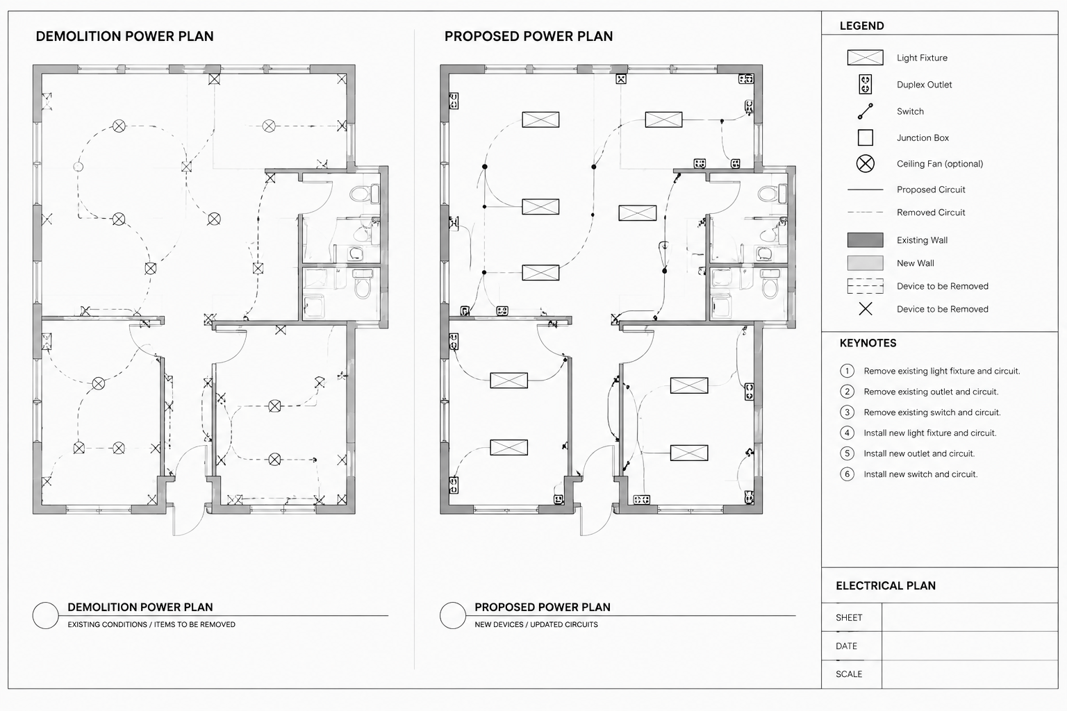
Before renaming a type, search all applicable files and references. Check lighting plans, enlarged plans, fixture schedules, legends, ceiling coordination drawings, controls documentation, details, and equipment lists. If old and new fixture types coexist during a phased change, make their status explicit rather than reusing one identifier for different definitions.
Copied plans and repeated floor layouts need particular attention. A tag updated in one area may remain unchanged in a typical unit, mirrored plan, or linked detail. A drawing comparison or attribute extraction can help identify these discrepancies, but visual review is still necessary.
Final Quality-Control Checklist
- Every visible fixture tag is legible at the intended plot scale.
- Each fixture type has a matching schedule entry or documented exception.
- Tag values use consistent spelling, case, spacing, and suffix formatting.
- Rotated and mirrored symbols retain readable tag text.
- Fixture tags are visually distinct from circuit and control identifiers.
- Emergency, existing, relocated, and special-status fixtures follow the drawing legend.
- Leaders point clearly to the intended fixture where proximity is insufficient.
- Schedule changes have been reconciled across plans, details, and related diagrams.
- No obsolete fixture tags remain in hidden, frozen, or copied plan areas.
- Final PDF output preserves text clarity and does not mask tags with background graphics.
A reliable fixture-tag workflow is less about elaborate coding and more about controlled relationships. When symbols, tags, schedules, and controls are treated as coordinated parts of one documentation system, lighting plans become easier to read, revise, review, and hand off.
Define the Authoritative Source for Each Value
Coordination becomes more reliable when the project team identifies where each type of information is maintained. The fixture schedule may govern the fixture type definition, while the lighting plan governs placement and the control documentation governs zone relationships. When the same property is manually entered in several locations, conflicting values can survive unnoticed.
A practical drawing setup distinguishes between authoritative data and displayed references. A plan tag may display the scheduled type, but that does not necessarily make the plan annotation the master definition. Documenting this distinction helps drafters understand where a revision should begin and which related views require checking.
Review Relationships Instead of Isolated Labels
A tag can be spelled correctly and still be wrong for its context. Quality control should therefore examine the relationship among the symbol, identifier, schedule entry, control assignment, and mounting condition. This is especially important where similar fixture graphics represent different scheduled products or operating conditions.
Useful review questions include:
- Does the symbol family or block agree with the displayed fixture type?
- Does the type resolve to the intended schedule definition?
- Are control and circuit references stored separately from the fixture identifier?
- Does the annotation remain clear in crowded, rotated, mirrored, or repeated layouts?
- Can a reviewer trace special conditions to the applicable legend, note, or detail?
Protect Coordination During File Exchange
Tags may behave differently when drawings are exported, referenced, bound, flattened, or converted for review. Attributes can become plain text, annotation visibility can change, and fonts or masks can affect legibility. The delivered drawing and published sheet should therefore be checked in addition to the working file.
For project handoff, retain enough structure for future editors to distinguish fixture geometry from tag data. Consistent attribute names, layer use, text styles, and documented conventions make later updates easier than a file in which identifiers have been exploded or embedded unpredictably in symbol geometry.
Use Exception Reports to Focus Review
Automated extraction is most useful when it highlights exceptions rather than replacing visual review. A comparison can flag plan types without schedule matches, unexpected spelling variants, blank attributes, or schedule entries with no visible plan use. The reviewer can then determine whether each item is an error, an intentional exception, or information belonging to another drawing package.
This combination of data comparison and sheet-level inspection provides a stronger review than either method alone. Data checks find inconsistencies across large drawing sets, while visual checks reveal overlapping annotations, unclear leaders, masked text, and ambiguous graphic associations.
Frequently Asked Questions
Should every lighting fixture symbol have a visible type tag?
Not necessarily. Repetitive areas may use representative tags, grouping notes, or another documented convention. The drawing must still make it clear which fixtures share the identified type and where any exceptions occur.
Is a control-zone label part of the fixture tag?
Usually it is better treated as a separate annotation because fixture type and control assignment describe different relationships. Fixtures of the same type can belong to different control groups, and one control group can include different fixture types.
Should the fixture tag rotate with the symbol?
The symbol may rotate to follow the architectural layout, but the tag should remain readable in the intended sheet orientation. Symbol rotation and annotation orientation should be managed separately when the CAD workflow allows it.
What causes unmatched fixture tags and schedule entries?
Common causes include copied geometry, inconsistent attribute values, revised identifiers that were not updated everywhere, punctuation or capitalization differences, and schedule entries retained for alternates or other drawing areas. Each mismatch should be reviewed rather than automatically deleted.
Can fixture tags contain circuit and emergency information?
A project convention may display related information near the type identifier, but each value should remain visually and logically distinguishable. The legend or schedule should explain the convention so readers do not mistake circuit, control, or operating-status information for part of the fixture type.
Why check the published PDF when the CAD file looks correct?
Plotting and export can change text visibility, masking, lineweight relationships, font appearance, and annotation display. Reviewing the published sheet confirms that the tag remains legible and clearly associated with the intended fixture.
Leave a Reply
You must be logged in to post a comment.