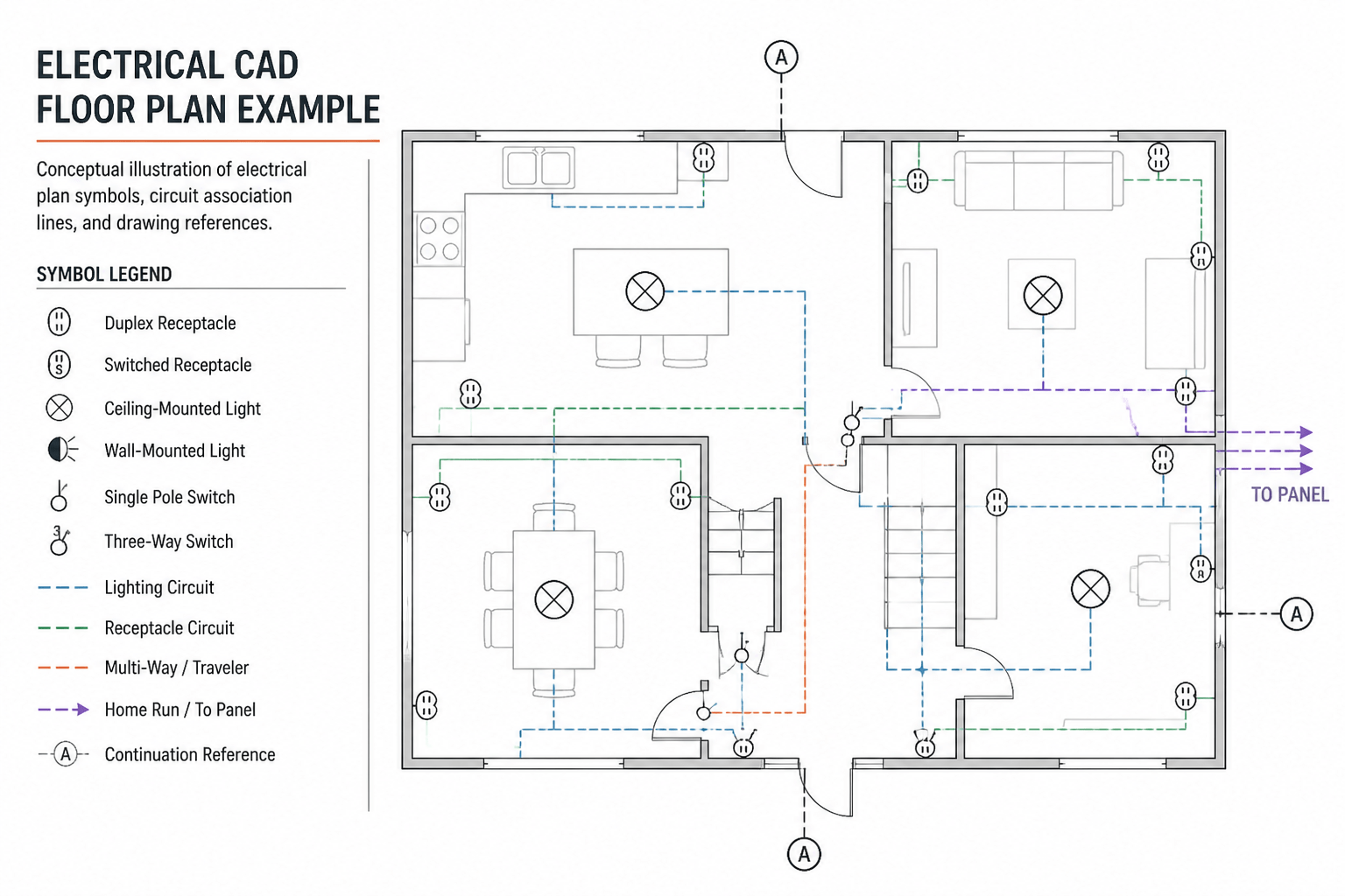
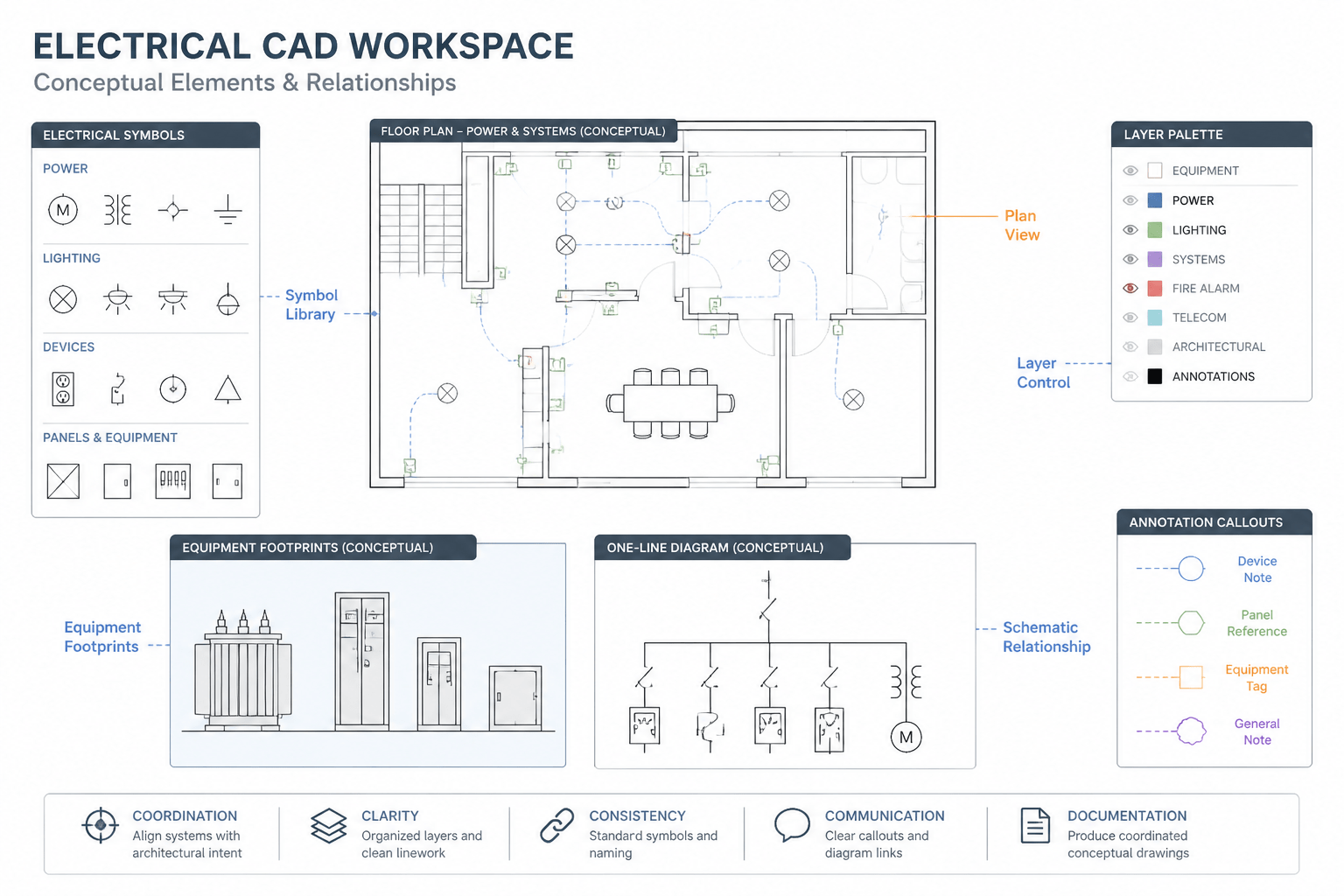
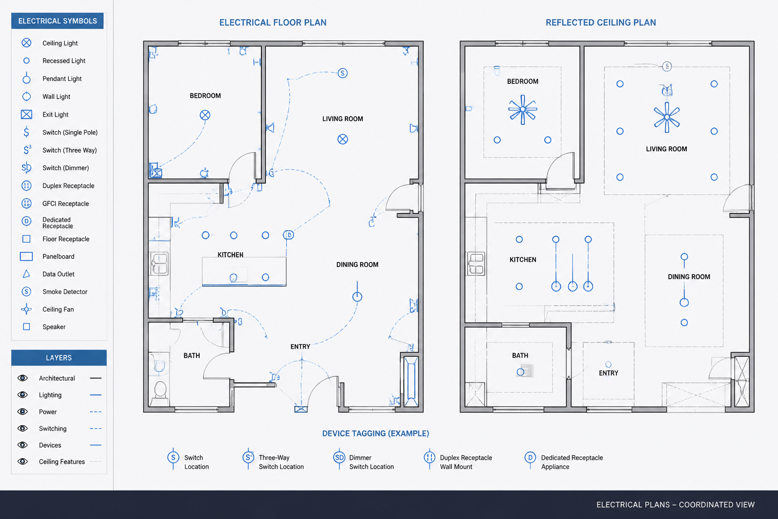
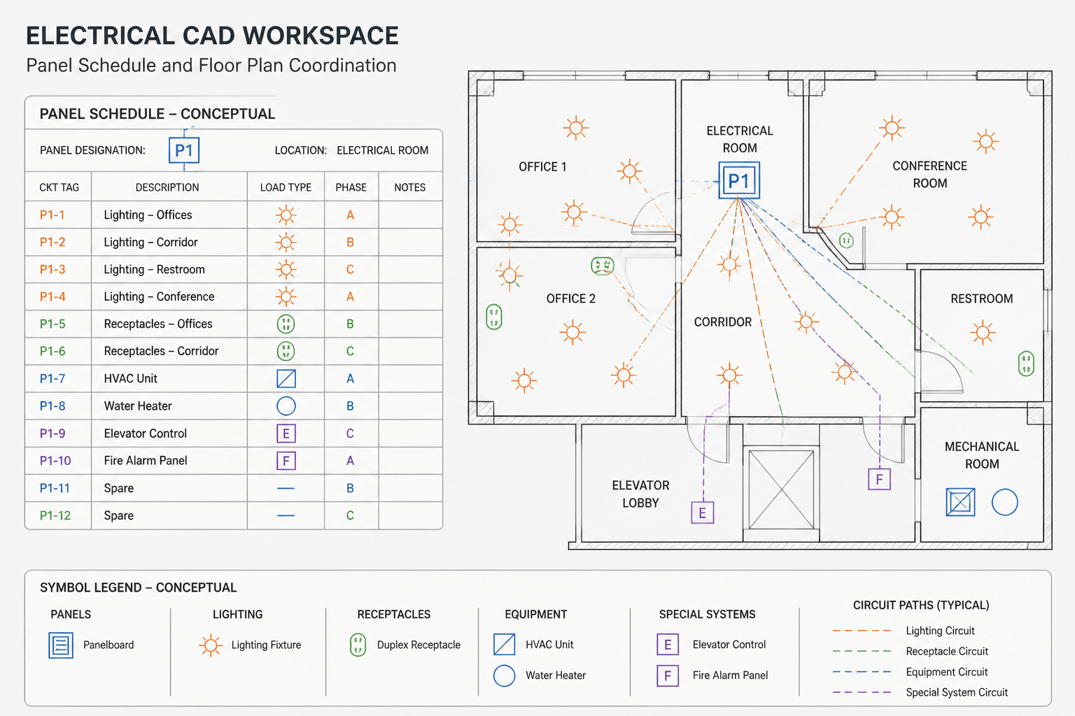
Electrical floor plans use a compact graphic language to show how devices relate to circuits without drawing every conductor in full physical detail. Receptacles, switches, lighting fixtures, equipment connections, and circuit references may appear close together on a plan, while their complete electrical relationships are communicated through linework, symbols, tags, and notes.
Learning how to read electrical circuit lines in CAD plans helps designers, detailers, reviewers, estimators, and other project participants understand the intended relationship between devices. It also makes CAD coordination easier because a drawing can be checked for missing connections, ambiguous references, and inconsistent annotations without treating the plan as a wiring installation instruction.
What an electrical circuit line represents
A circuit line is a graphic indication that devices are associated with the same electrical circuit or control relationship. Depending on the drawing convention, it may represent a branch-circuit connection, a switched-leg relationship, a control path, or a connection to equipment. The line does not necessarily show the exact route that conductors will follow in the finished installation.
On a plan, circuit lines are usually drawn between related symbols or from a device group toward a circuit reference. Their appearance may vary by project. Some drawings use continuous lines, while others use angled segments, leader-style graphics, or compact tags that reduce visual congestion. The project legend and general notes should always take priority over assumptions based on another drawing.
Common elements to identify first
Before following a line across a crowded plan, identify the symbols and annotations that establish its meaning. The most useful elements include:
- Device symbols: Receptacles, switches, luminaires, disconnecting means, equipment connections, and other electrical devices shown in plan view.
- Circuit tags: Short labels that associate a device or group of devices with a circuit, panel, or equipment source.
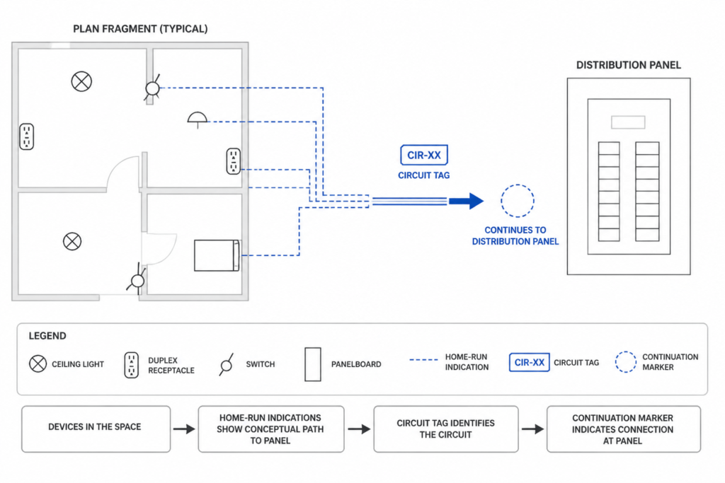
- Home-run graphics: Lines or arrows that indicate a circuit continues back toward a panel or other distribution point.
- Switch-control lines: Graphics that identify which lighting fixtures or controlled devices operate from a particular switch.
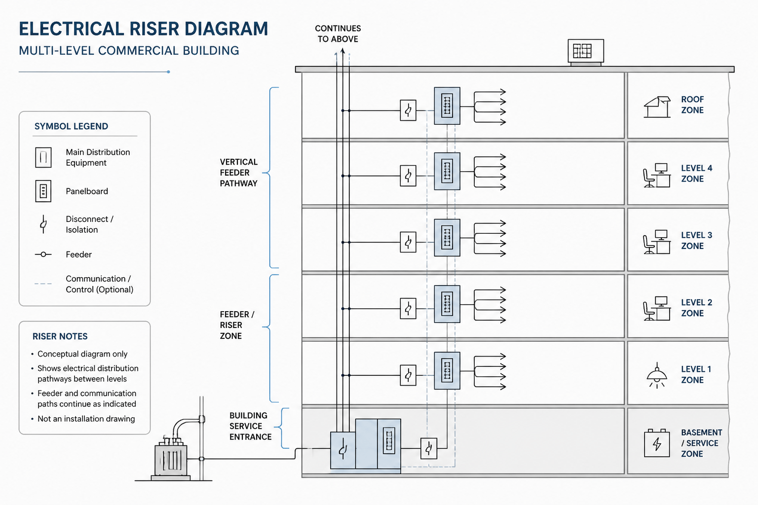
- Continuation references: Notes or symbols indicating that a circuit, system, or diagram continues elsewhere.
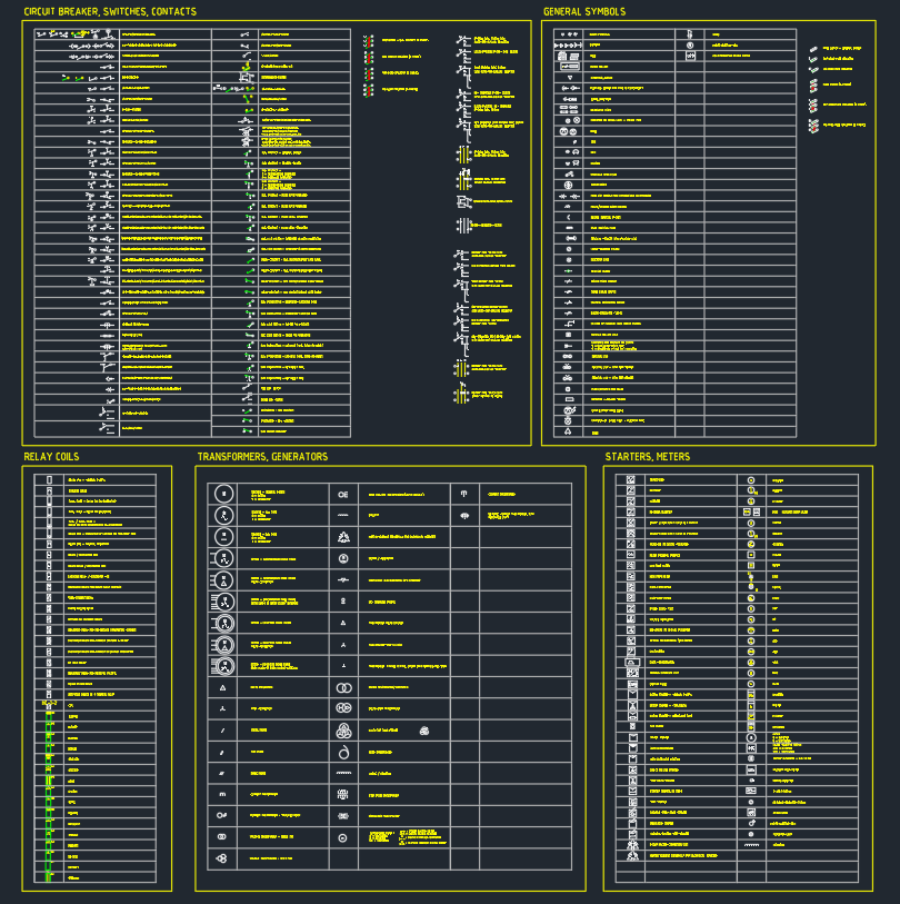
- General notes and legends: Project-specific explanations for abbreviations, line styles, symbol variations, and annotation rules.
A line should not be interpreted independently from these items. The same graphic style may have different meanings on different projects, and a symbol that appears similar to another may represent a different device category.
How to follow a home-run indication
A home run is a drafting convention used to show that a circuit path returns toward a panel or distribution location. Instead of drawing a conductor path through every room and corridor, the plan may show the connected device group and then use an arrow, angled line, or circuit tag to identify the source direction.
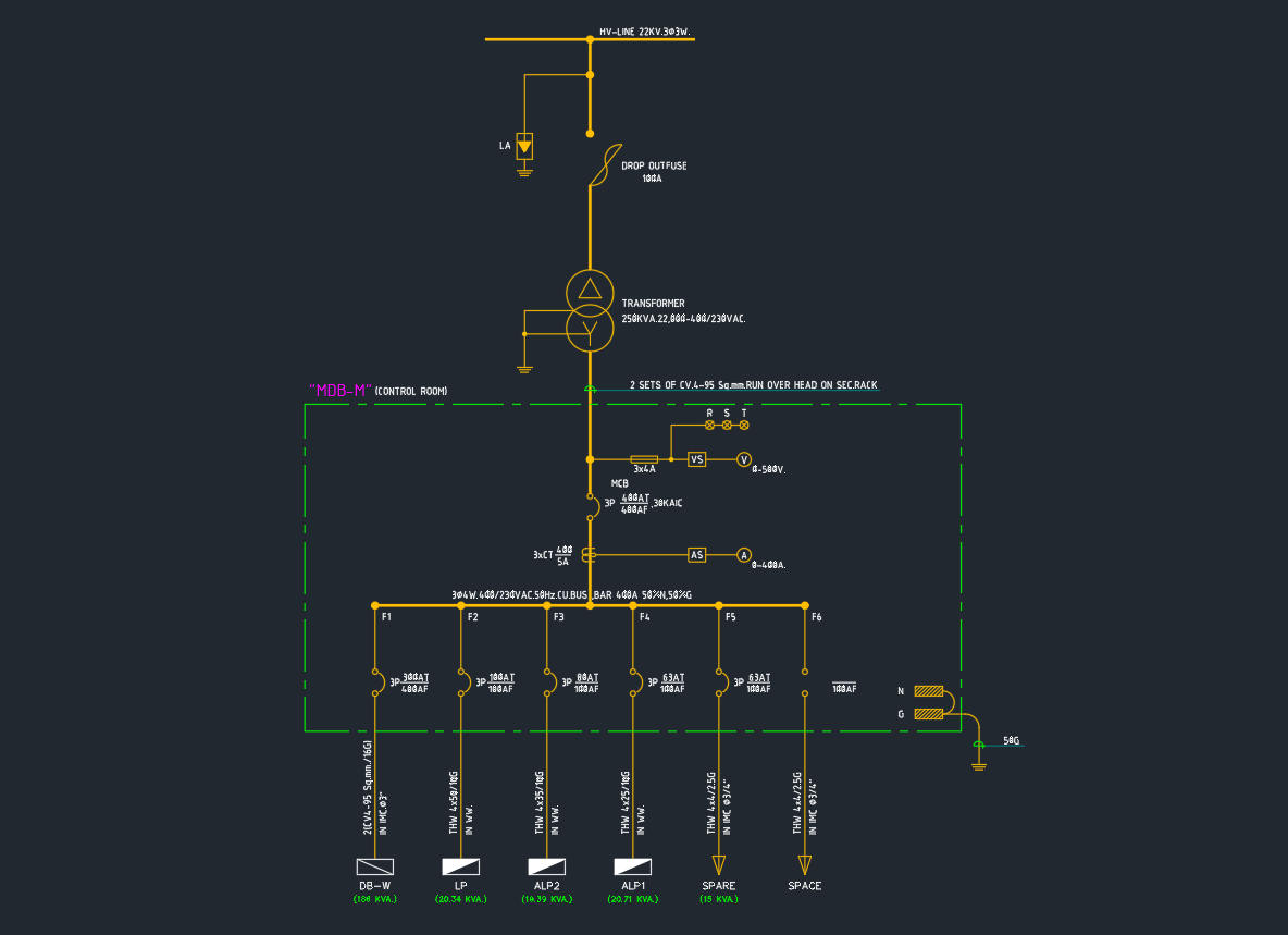
To read the indication, begin at the connected device or group. Follow the line to its arrowhead, tag, or reference note. Then compare that information with the panel identification, circuit schedule, or single-line documentation available for the project. The purpose of this comparison is to confirm drawing coordination, not to infer missing conductor details or protective-device information.
Several home runs may leave the same area and overlap visually. Clear drafting typically separates the lines, staggers tags, or uses a consistent annotation location. If the source cannot be determined confidently, the item should be marked for clarification rather than resolved by guessing.
Distinguishing circuit lines from switch-control lines
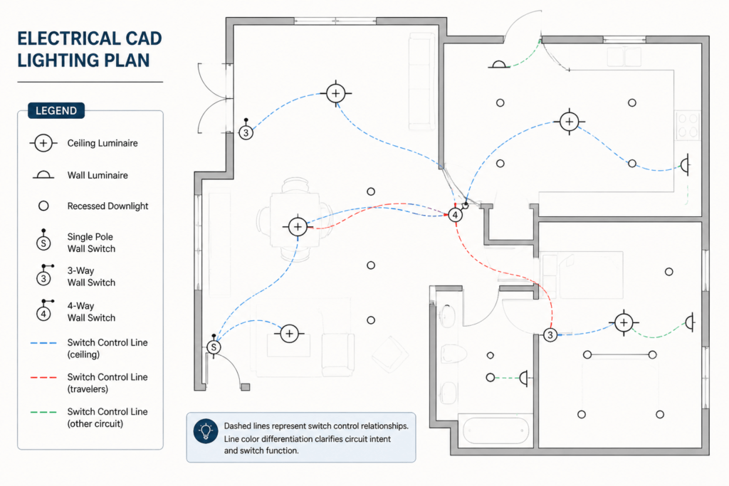
Lighting plans often contain two related but different types of graphic relationships. One may identify the circuit or source serving a lighting group. Another may show which switch controls that group. Confusing these relationships can make a plan appear to connect a switch directly to a panel when the drawing is only showing control intent.
Look for the project’s line-style convention. A switch-control line may use a different pattern, termination, or path than a circuit association line. The controlled fixtures may also carry matching switch-leg identifiers or control labels. When several switches are located together, tags are especially important because a single line can otherwise be difficult to trace.
| Drawing element | What it usually communicates | What it does not prove by itself |
|---|---|---|
| Solid or segmented circuit line | An electrical relationship between shown devices or a device group | The exact installed conductor route |
| Home-run arrow or reference | Direction or association toward a source location | Conductor size, raceway content, or field installation method |
| Switch-control line | Which fixture or device is controlled by a switch | The complete control wiring arrangement |
| Circuit tag | A reference used to coordinate the plan with schedules or distribution information | Unlisted electrical characteristics |
| Continuation symbol | That the graphic or system relationship continues elsewhere | The destination unless the related reference is identified |
Reading continuation references
Continuation references are used when a circuit or system cannot be shown clearly in one location. A plan may direct the reader to another area, a different drawing, a riser, a detail, or a related diagram. The reference may be attached to a line, device, equipment symbol, or note.
Read both sides of the reference. First, identify what leaves the current drawing area. Next, locate the matching reference and confirm whether the graphic continues as a circuit, control relationship, equipment connection, or communications path. Matching labels are more reliable than visual proximity because a continuation may cross a sheet boundary or move between drawing types.
In CAD, continuation references should remain legible when the plan is plotted or viewed at a reduced scale. Text that is too close to symbols, hidden behind hatches, or placed on an unsuitable layer can make a valid connection appear incomplete.
CAD practices that improve circuit-line readability
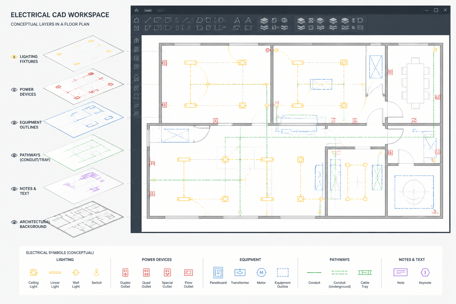
Good CAD organization supports interpretation but does not replace electrical review. Circuit graphics, device symbols, annotation, and architectural backgrounds should be managed so that each category can be displayed, hidden, or reviewed without damaging the drawing’s meaning.
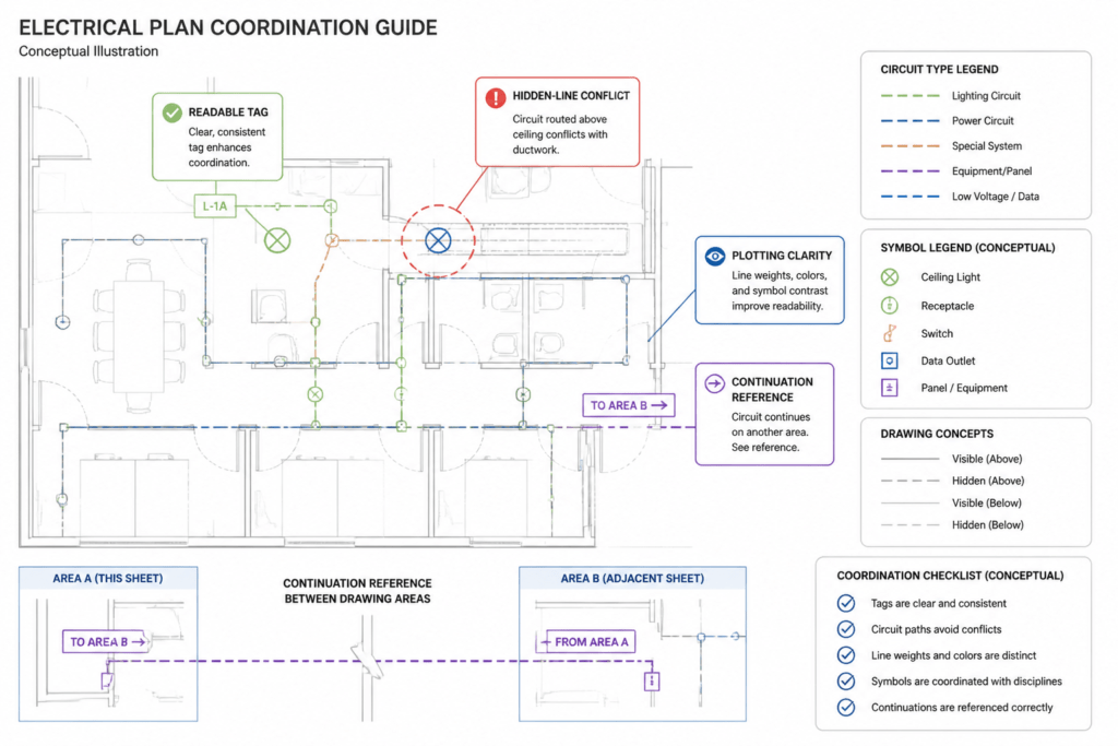
- Use consistent linework: Apply the project’s approved color, linetype, and lineweight conventions consistently across similar circuit relationships.
- Separate annotation from geometry: Keep circuit tags and explanatory notes easy to select and revise without modifying device blocks or background information.
- Control display order: Make sure circuit lines do not disappear beneath hatches, equipment outlines, or imported backgrounds.
- Use block attributes carefully: Device blocks may contain tags, identifiers, or orientation information. Check that attributes remain visible and do not duplicate nearby manual text.
- Avoid unnecessary crossings: Reroute graphic lines or use clear references when crossings could be mistaken for electrical connections.
- Check plotted output: A line that looks distinct in model space may become unclear after scaling, grayscale plotting, or PDF export.
A practical review sequence
When reviewing a plan, work from broad relationships to individual annotations:
- Read the legend and general notes to understand the project’s symbols and line conventions.
- Locate the electrical source or distribution reference associated with the area under review.
- Identify device symbols and group them by apparent circuit or control relationship.
- Trace home-run graphics and continuation references without assuming an unshown route.
- Compare circuit tags with related schedules or diagrams where available.
- Inspect congested areas for ambiguous crossings, duplicate tags, hidden text, or disconnected-looking lines.
- Record uncertainties as coordination questions rather than changing the drawing based on an unsupported interpretation.
Common interpretation mistakes
One frequent mistake is treating every line as a physical conductor route. Most floor-plan graphics are diagrammatic and are intended to communicate relationships efficiently. Another mistake is assuming that a circuit tag contains all information needed to define the circuit. Tags are coordination references; the associated project documents provide the broader context.
It is also easy to overlook the difference between a device’s location and its circuit source. A receptacle may be shown near one piece of equipment while its source relationship is represented by a remote reference. Similarly, several lighting fixtures may be controlled together even when their symbols are distributed across a room or zone.
Use the drawing as a coordinated reference
Electrical circuit lines are most useful when read as part of a coordinated drawing set. The plan communicates location and relationships, while legends, schedules, diagrams, details, and notes provide additional identification. For CAD users, the goal is to preserve that relationship clearly through consistent symbols, readable tags, disciplined layer display, and careful plotting.
When a line, tag, or continuation reference is unclear, the correct response is to verify it against the project’s other documents and established conventions. A conceptual CAD plan can support review and coordination, but it should not be treated as a substitute for a project-specific electrical design, installation document, or field verification.
Leave a Reply
You must be logged in to post a comment.