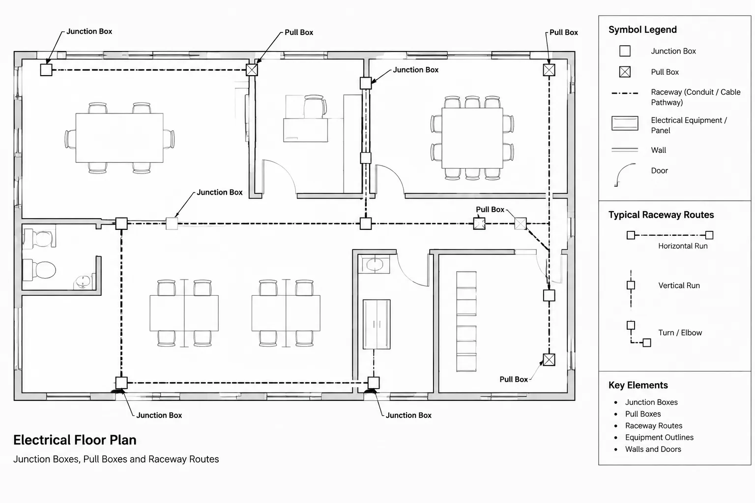
Junction boxes and pull boxes may occupy little space on an electrical plan, but they often carry significant coordination information. A box can identify a wiring transition, support a branch-circuit route, provide a pulling point, or connect equipment that cannot be represented clearly with circuit lines alone. If the symbol, tag, and related notes are incomplete, installers and reviewers may interpret the same drawing differently.
A useful junction box plan CAD workflow therefore goes beyond inserting a generic square or circle. The drafter must show the box in the correct context, distinguish its purpose, coordinate it with raceway routing and circuit documentation, and direct the reader to schedules or details when the plan cannot carry all required information.
Junction Box, Pull Box, and Device Box: Drawing Intent Matters
These terms should not be treated as interchangeable labels. Their exact application depends on the project, but each generally communicates a different drawing purpose:
- Junction box: A location where conductors or cables may branch, transition, or connect. On plans, it may also represent a concealed connection point associated with equipment.
- Pull box: A point provided along a raceway route to support conductor installation or a change in routing. It is commonly coordinated with larger distribution pathways.
- Device or outlet box: A box associated directly with a receptacle, switch, control, luminaire connection, or another identified device.
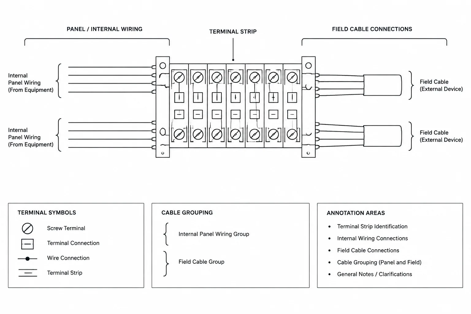
- Terminal or connection enclosure: An equipment-related enclosure used to organize or terminate conductors. Its documentation may belong on a plan, equipment elevation, schematic, or connection detail.
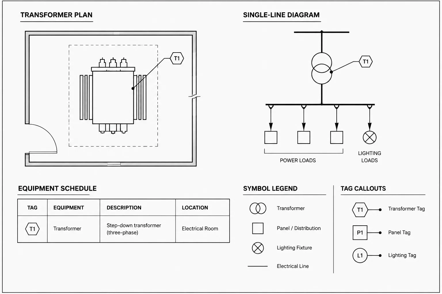
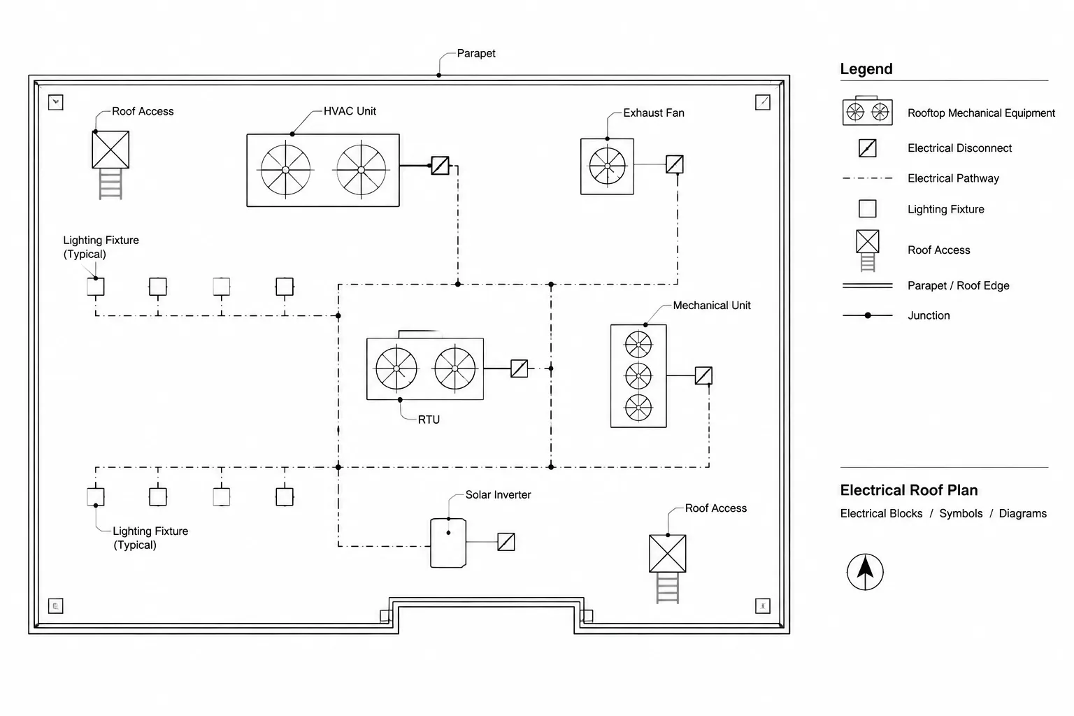
The symbol should express the intended category rather than merely showing that an unspecified box exists. A project legend can establish the base graphic, while tags and notes clarify each occurrence.
Choose Symbols That Remain Clear in the Full Drawing Set
A junction box symbol must be readable at the plotted scale and distinguishable from nearby outlets, equipment connection points, and architectural markers. Avoid relying on color as the only method of differentiation because printed sheets, reduced PDFs, and grayscale plots may remove that distinction.
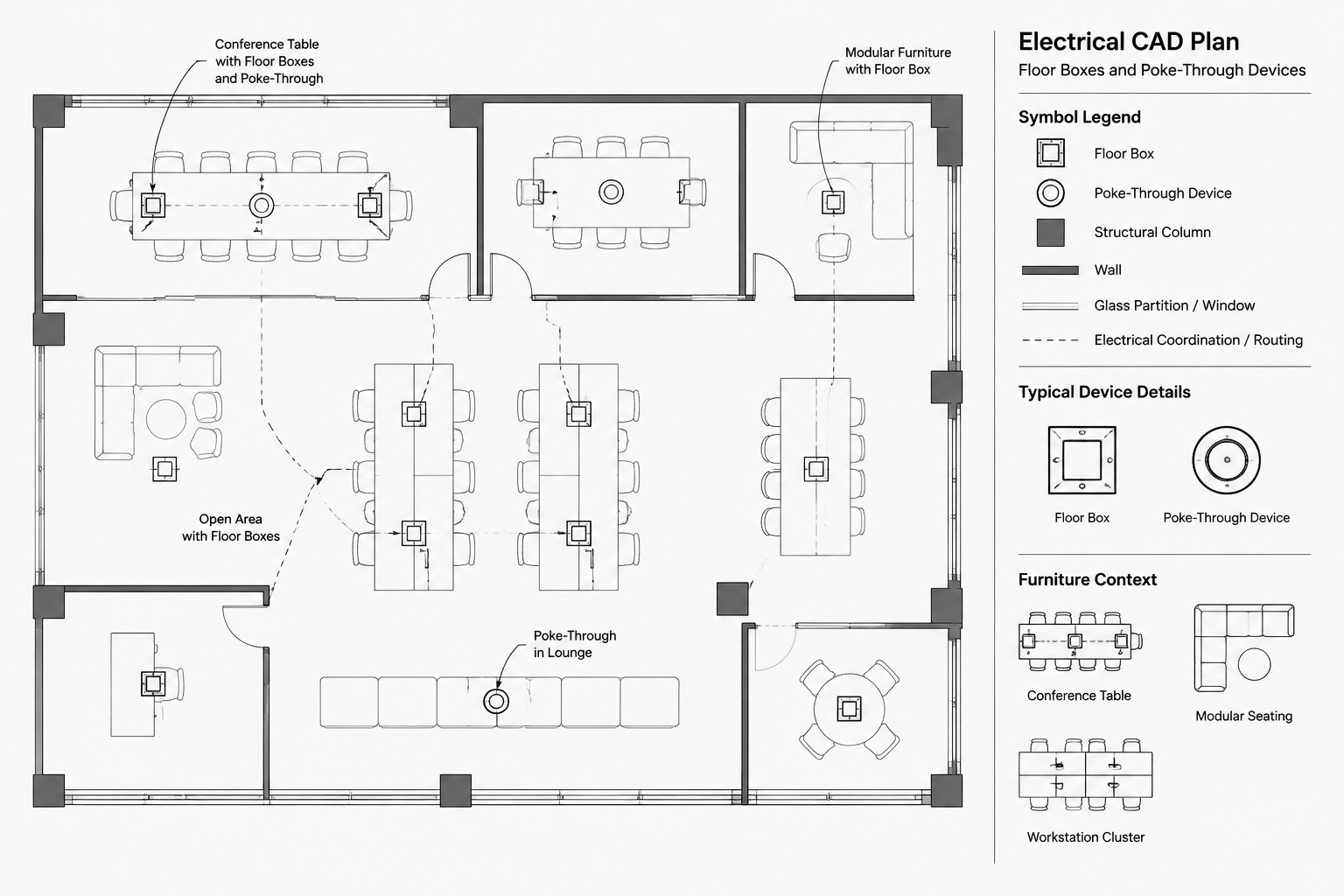
A practical symbol system may use a consistent geometric shape with a short internal identifier or an adjacent tag. Pull boxes used for distribution routing can have a separate graphic from branch-circuit junction boxes. Boxes associated with special systems should follow the graphic language of those systems rather than being mixed into the power legend without explanation.
Before adopting a symbol from a CAD library, check:
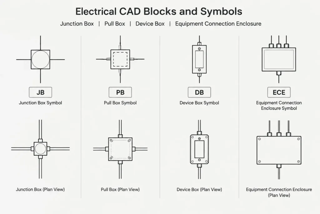
- Whether it matches the project legend and office drafting conventions.
- Whether its text and linework remain legible at the intended sheet scale.
- Whether the insertion point supports accurate placement and rotation.
- Whether attributes are required for identifiers, circuits, systems, or detail references.
- Whether the same symbol could be confused with an architectural, mechanical, or fire protection marker.
A downloaded CAD block is a drafting resource, not automatic confirmation that the represented box or arrangement is appropriate for a project. Selection, sizing, accessibility, and installation conditions require project-specific verification.
Place the Box According to Its Coordination Context
Symbol placement should communicate where the box belongs and what it serves. A box shown in open plan space without a relationship to a wall, ceiling, route, or equipment item provides little useful information.
Wall and equipment connections
For a wall-mounted or equipment-related box, place the symbol relative to the architectural wall or equipment footprint. Use a leader when exact placement would otherwise be ambiguous. If the box belongs above, below, behind, or within another assembly, state that relationship through an elevation reference, mounting note, or coordinated detail rather than trying to imply depth on a floor plan.
Above-ceiling locations
Boxes located above accessible ceiling areas should be coordinated with the reflected ceiling plan, structure, ductwork, piping, lighting, and access conditions. The electrical floor plan may show the approximate horizontal location, but a ceiling coordination view or enlarged plan can communicate the intended relationship more effectively in congested areas.
Distribution pathways
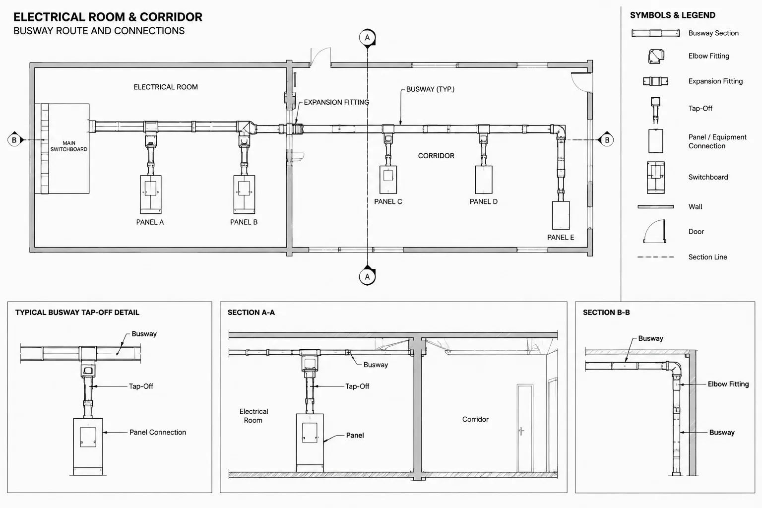
Pull boxes associated with feeders, site raceways, or major conduit routes should align visibly with the documented pathway. Where a route continues to another plan, level, or detail, use consistent continuation references. Do not leave a box at the end of a line unless the termination or continuation is explained.
Develop a Tagging Method Before Repeating Symbols
Repeated untagged symbols force the reader to depend on nearby notes and visual assumptions. A structured identifier makes each box easier to track across plans, schedules, details, and revisions.
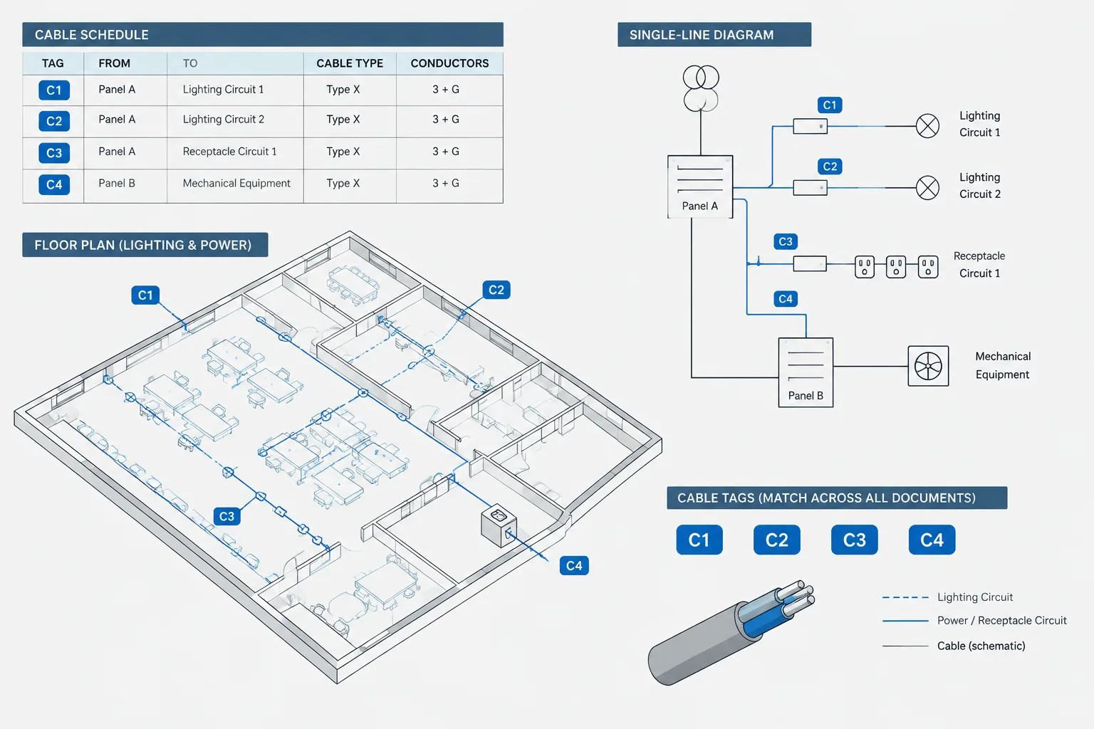
A tag can combine a box category with a unique identifier, but the format should follow the project’s established naming system. Keep identifiers stable once they have been used in coordination documents. Renumbering late in the project can break references in schedules, markups, and consultant drawings.
Useful tag attributes may include:
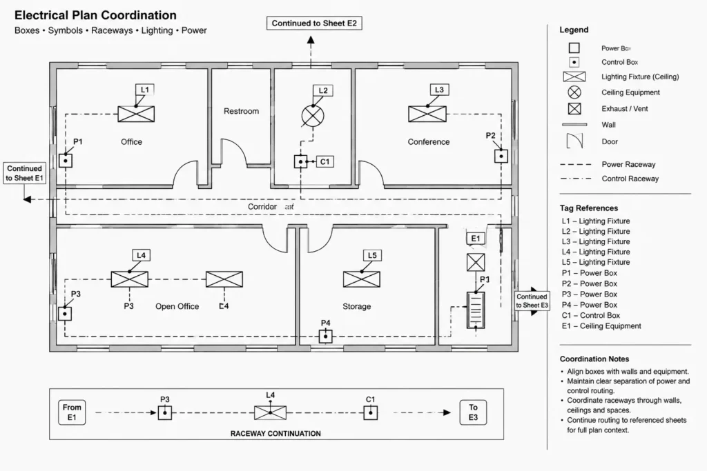
- Unique box identifier.
- System or service designation.
- Associated panel, circuit, feeder, or source reference.
- Equipment served.
- Schedule or detail reference.
- Location or level designation when needed for coordination.
Not every item belongs inside the visible tag. The plan should remain readable, with extended information stored in a schedule or note where appropriate.
Build a Box Schedule for Repeated or Information-Rich Items
A schedule is valuable when the project contains many boxes with differing purposes or documentation requirements. It should supplement the plan rather than duplicate every nearby annotation.
| Schedule field | Documentation purpose |
|---|---|
| Box ID | Connects the schedule row to the plan symbol. |
| Type or function | Distinguishes junction, pull, connection, or system-specific use. |
| Location | Identifies the associated room, area, level, or route. |
| Source reference | Links the box to a panel, circuit, feeder, or upstream equipment item. |
| Load or equipment served | Explains the downstream purpose without tracing every line visually. |
| Detail reference | Directs the reader to an elevation, section, or installation concept. |
| Remarks | Records coordination notes that do not fit cleanly on the plan. |
Include only fields that the design team can maintain reliably. Empty or speculative schedule columns create false expectations and often become outdated.
Coordinate Circuit Lines and Raceway Routes
A box symbol should not interrupt the logic of the electrical routing. Circuit lines, conduit paths, or cable routes should connect cleanly to the symbol or terminate with an unmistakable leader. When several routes meet at one box, arrange the linework so that the reader can identify each incoming and outgoing path.
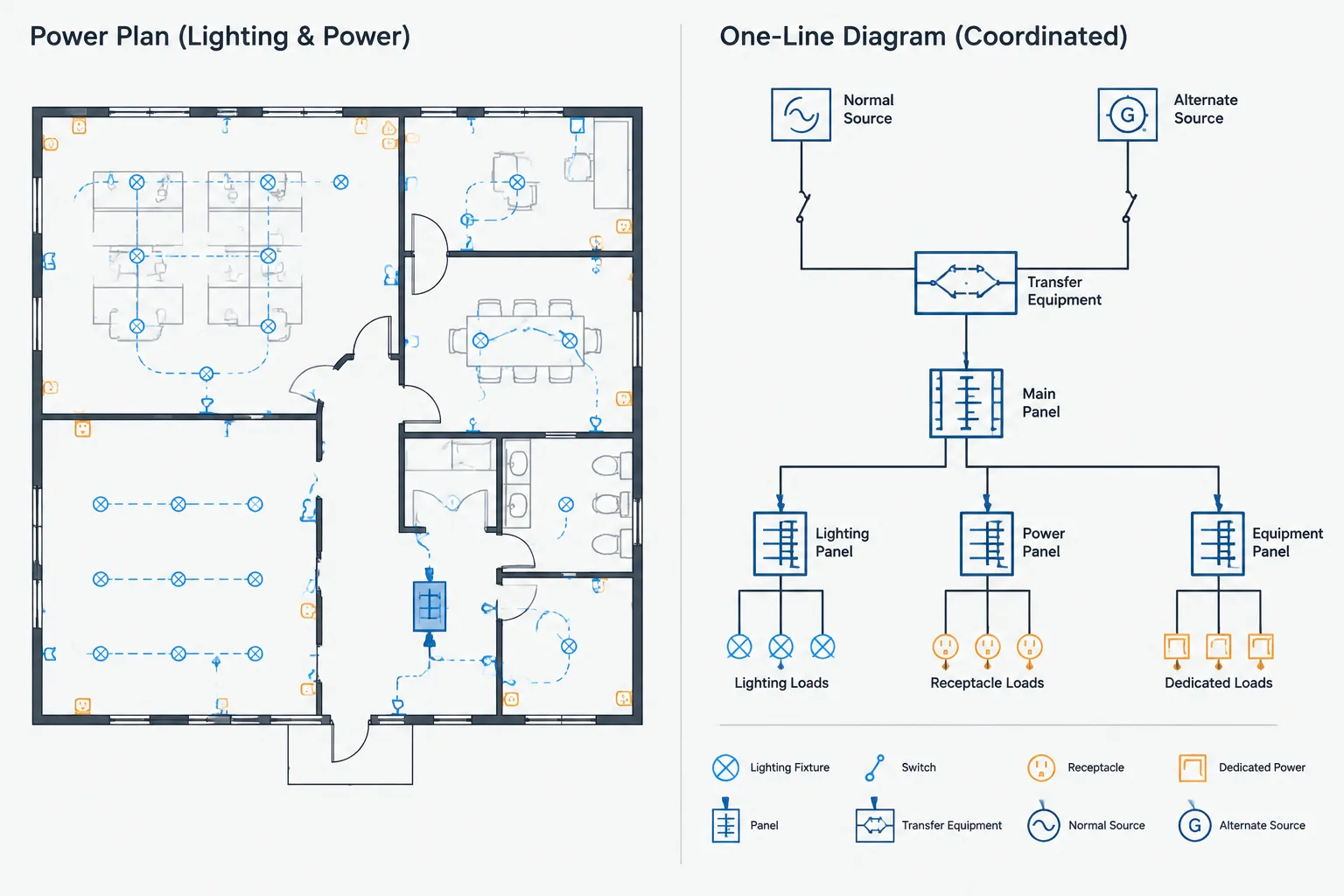
Avoid using one graphic line to represent multiple unrelated ideas. For example, a branch-circuit connection, a feeder raceway, and a control cable should not appear identical if their distinction affects interpretation. Layers, linetypes, labels, and separate diagram views can help, but each method must remain understandable when plotted.
Where routing is diagrammatic, state that intent in the drawing notes. A clean schematic path can be more useful than a falsely precise route, provided that required coordination points and connection relationships are still documented.
Use Details When the Plan Becomes Overloaded
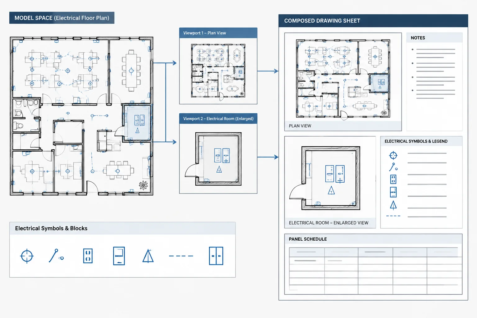
A floor plan is usually not the best location for every enclosure characteristic, entry direction, support relationship, or connection arrangement. Use an enlarged plan, section, elevation, or diagram when spatial or functional information cannot be shown clearly at the main plan scale.
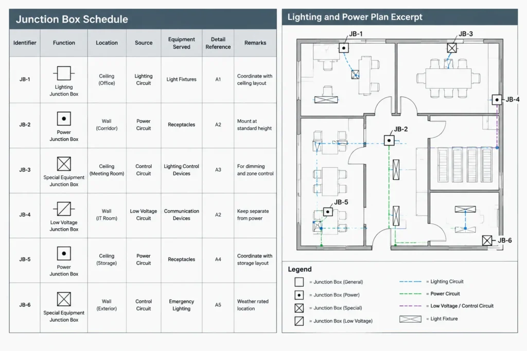
A supporting detail may illustrate:
- The relationship between a box and adjacent equipment.
- Multiple raceway approaches or departures.
- A wall, ceiling, or structural coordination condition.
- A transition between wiring methods or documented systems.
- Access intent and the relationship to surrounding construction.
Keep the detail reference adjacent to the relevant tag, and verify that the referenced detail actually addresses that box type. Generic details should not be applied automatically to conditions they do not depict.
Organize Layers for Editing and Plot Control
Place box symbols, tags, circuiting, pathway linework, and notes on layers that support selective display and quality control. The exact layer names should follow the project CAD standard, but the underlying separation should allow the team to isolate major information categories.
Do not place all box-related content on a single layer if doing so prevents useful plotting or editing. Conversely, excessive layer fragmentation can make the file difficult to manage. The goal is a predictable structure that supports plan production, coordination backgrounds, and final plotting.
If box blocks contain attributes, check whether attribute text inherits the intended layer and plotting behavior. Nested geometry can appear correctly in one file but plot unexpectedly when inserted or referenced elsewhere.
Quality-Control Checklist
- Confirm that every box symbol appears in the legend or is otherwise clearly identified.
- Verify that unique tags are not duplicated unintentionally.
- Trace connected lines to ensure sources, destinations, and continuations are understandable.
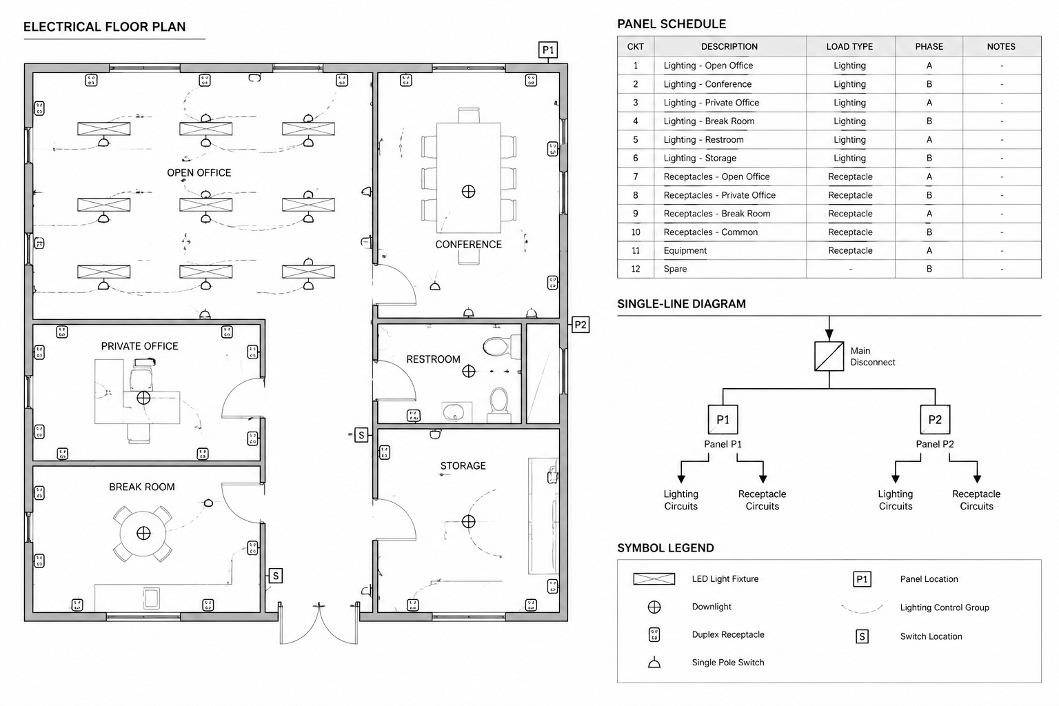
- Compare plan tags with box schedules, equipment schedules, and diagram references.
- Check that boxes shown on enlarged plans agree with the overall plan.
- Review architectural and reflected ceiling backgrounds for access and coordination conflicts.
- Confirm that demolished, relocated, existing, and new boxes use the project’s status graphics consistently.
- Inspect the plotted sheet and reduced PDF, not only the CAD model view.
- Remove abandoned leaders, obsolete notes, and schedule rows left by revisions.
- Flag unresolved sizing, construction, or system questions for the responsible designer rather than guessing.
A Clear Box Symbol Is Part of a Larger Documentation System
Effective junction box and pull box drafting depends on relationships. The symbol must connect logically to routing, circuit information, equipment, schedules, details, and the project legend. When those relationships are coordinated, even a small plan symbol can convey substantial design intent without cluttering the sheet.
Build the workflow around consistent tags, purposeful layers, readable plotting, and disciplined cross-references. Treat CAD blocks as reusable graphic components, then add the project-specific information needed to make each occurrence meaningful and verifiable.
Leave a Reply
You must be logged in to post a comment.