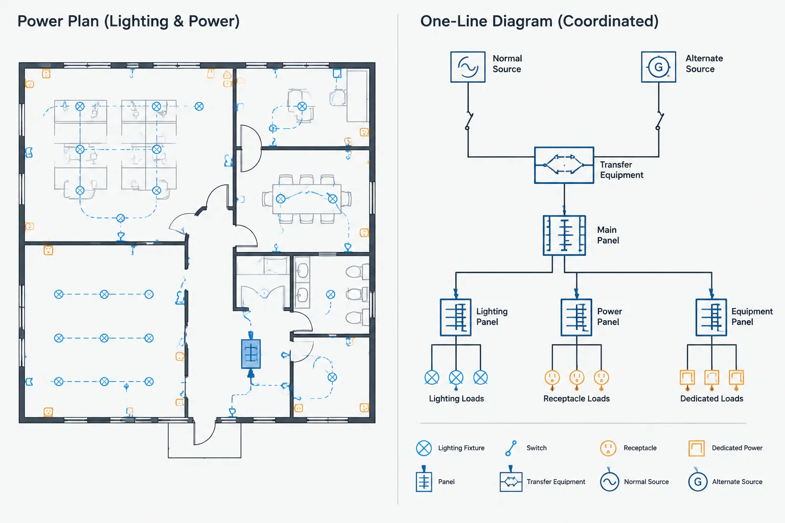
Coordinating normal and backup power is a drawing-set problem, not merely a symbol-selection task. A source designation shown on a floor plan must remain consistent with the associated panel schedule, distribution diagram, equipment layout, legend, and related annotations.
The following guidance presents a documentation workflow for maintaining that continuity. It focuses on source identity, transfer relationships, CAD data, cross-sheet review, and revision control while leaving project-specific classifications and operating requirements to the approved electrical design.
Projects with generators, uninterruptible power supplies, transfer equipment, or other alternate sources require more than a few special symbols. The drawings must communicate which source serves each load, how power changes between sources, and where the associated equipment is located. If that information is inconsistent, a plan may imply one power path while the one-line diagram or panel schedule shows another.
A reliable CAD workflow treats source identity as coordinated project data. It should appear consistently in equipment tags, circuit annotations, schedules, diagrams, legends, and details. This guide explains how to organize that information without relying on color alone or turning the floor plan into a wiring schematic.
Begin with the project’s power-source categories
Before drafting, identify the source categories defined by the electrical design. These may include normal utility power, generator-backed power, uninterruptible power, or other project-specific sources. Some projects also distinguish regulated emergency, legally required standby, and optional standby systems. Those terms are not interchangeable, so use only the classifications established by the design team and applicable project criteria.
Create a small source matrix before placing devices. For each category, record:
- The approved source abbreviation or identifier
- The panels, switchboards, transfer equipment, and distribution sections involved
- The loads or spaces served
- The plan annotation method
- The linetype, hatch, or other graphic convention
- The schedules and diagrams where the category must appear
This matrix becomes a drafting control document. It helps prevent one sheet from using a generic backup-power note while another uses a more specific system designation.
Map the source path before detailing floor plans
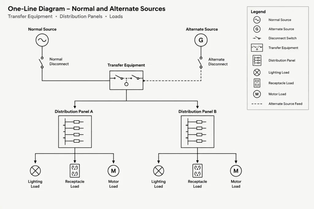
The one-line diagram is usually the clearest place to establish the overall distribution path. Show the normal source, alternate source, transfer function, downstream distribution equipment, and major loads at the level of detail appropriate to the project. The diagram should clarify functional relationships without attempting to show physical routing.
Trace each distribution path from source to load and verify that every equipment tag has a corresponding destination. A panel shown downstream of transfer equipment should retain that identity wherever it appears. If a panel is divided into sections supplied by different sources, the documentation must make that division clear rather than treating the panel as a single undifferentiated object.
Keep source, transfer, and load identities separate
These three concepts are related but should not be merged into one ambiguous label:
- Source identity indicates where power originates.
- Transfer function indicates where or how a load changes between available sources.
- Load identity indicates the equipment, panel, circuit, or device being served.
Separating them makes revisions easier. A load may remain in the same location while its serving panel or transfer arrangement changes.
Use a coordinated annotation strategy
Source distinctions should remain understandable when drawings are printed in monochrome, reduced, exported, or viewed through software with altered display settings. Color can be a useful secondary cue, but it should not carry the full meaning.
| Drawing method | Best use | Coordination caution |
|---|---|---|
| Equipment and panel tags | Identifying the serving distribution path | Keep abbreviations identical across plans, diagrams, and schedules |
| Distinct symbols | Differentiating device service categories | Explain every variation in the legend |
| Text suffixes or attributes | Adding searchable source data to blocks | Avoid long labels that obscure nearby plan information |
| Linetypes | Distinguishing feeders or diagram paths | Confirm that patterns remain legible at plotted scale |
| Hatches or screened areas | Identifying rooms, zones, or equipment groups | Do not cover architectural or life-safety information |
| Color | Improving on-screen review | Always provide a non-color cue |
For repeated devices, block attributes can carry source, panel, circuit, and device-type fields. This supports filtering and checking, but attributes should follow the same naming rules used in schedules. A smart block is helpful only when its data agrees with the visible drawing.
Coordinate each drawing type for its intended purpose
Floor plans
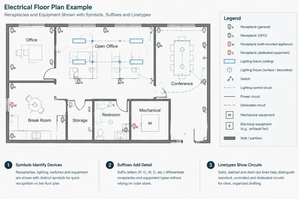
Floor plans communicate device locations, equipment locations, serving-panel references, circuit relationships, and relevant source categories. They should not reproduce the entire transfer sequence. Use concise tags and refer to the one-line diagram or control documentation for system operation.
Check devices near room boundaries, match lines, and enlarged-plan callouts carefully. These locations often produce duplicate symbols or conflicting circuit notes. When a plan is divided into views, establish which view owns the annotation.
One-line and riser diagrams
Diagrams should show the electrical relationship between sources, transfer equipment, distribution equipment, and downstream loads. Maintain the same equipment tags used on the plans. If a transfer device appears on the diagram, its physical location should be discoverable on an equipment plan, enlarged plan, or referenced detail where applicable.
Panel and equipment schedules
Schedules should reinforce source identity rather than introducing a new naming system. Panel names, source descriptions, and circuit references should agree with the plan and one-line diagram. Where a schedule distinguishes different load categories, use project-approved terminology and provide enough context for the reader to understand the grouping.
Equipment layouts
Layouts document physical placement and coordination. Show transfer equipment, source equipment, distribution sections, and related clear-space or access graphics only when those requirements have been verified for the project. Avoid assuming that a generic CAD block represents actual equipment dimensions. Manufacturer information and approved design data should control the final footprint.
Legends and general notes
The legend should explain visual distinctions, while notes should explain drawing conventions and scope. Do not place critical source information only in a general note. A reader should still be able to identify the serving system at the relevant device, equipment item, schedule, or diagram connection.
Organize CAD layers without fragmenting the drawing
Layers can separate normal-power devices, alternate-source devices, feeders, annotations, and diagram graphics. However, creating a layer for every minor category can make the file difficult to manage. Organize layers around useful visibility and plotting controls rather than every possible data field.
A practical layer structure may separate:
- Power-device symbols
- Source-specific annotations
- Feeder or circuit graphics
- Distribution equipment
- Transfer equipment
- Diagram text and connections
- Reference backgrounds and coordination zones
Use block attributes, schedules, or external project data for information that does not need independent layer control. This keeps source classifications searchable without producing an excessive layer list.
Handle revisions as system changes, not isolated edits
A source change can affect several documents at once. Moving a load from a normal panel to a generator-backed panel may require edits to the floor plan, circuit annotation, panel schedule, feeder documentation, one-line diagram, equipment schedule, and load summary. Changing only the device tag leaves the drawing set internally inconsistent.
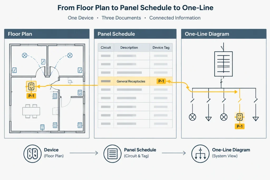
For each revision, follow the power path through the complete set:
- Confirm the revised source and distribution path.
- Update the affected device or equipment tag.
- Revise the serving-panel and circuit information.
- Check panel, feeder, and equipment schedules.
- Update one-line and riser connections.
- Review transfer-equipment references.
- Check legends, notes, and source-specific graphics.
- Remove obsolete lines, tags, and schedule entries.
Revision clouds can identify changed areas, but they do not replace this cross-sheet review.
Perform a source-to-load quality-control check
A useful final review is to select representative loads and trace them backward from the plan to the source. Start with a device or equipment item, find its panel and circuit, locate that panel in the schedule, then follow its upstream connection on the one-line diagram. Repeat the process in the opposite direction by starting at each alternate source and tracing downstream branches.
During this review, look for:
- Equipment tags that differ between plans and diagrams
- Panels assigned to the wrong source category
- Transfer equipment shown without clear upstream or downstream connections
- Devices that rely on color alone for identification
- Orphaned circuit lines or continuation references
- Source abbreviations missing from the legend
- Schedules that retain deleted or renamed equipment
- Generic blocks being mistaken for verified equipment footprints
Make source identity persistent
The strongest normal and backup power drawings do not depend on a single sheet or graphic effect. Source identity persists through equipment names, block data, circuit references, schedules, diagrams, and layouts. Each drawing communicates a different part of the system, but all of them describe the same distribution path.
That consistency makes the set easier to review, revise, coordinate, and interpret. It also allows CAD blocks and symbols to support the design intent instead of becoming isolated graphics with no dependable relationship to the rest of the documentation.
Build coordination around controlled identifiers
The most dependable workflow gives each relevant source, transfer device, distribution component, and load a controlled identifier. That identifier should be reused rather than reinterpreted on each drawing. Graphic styles may vary by sheet purpose, but the underlying equipment and source names should not.
When responsibilities are divided among team members, establish who controls each identifier and which document is treated as the primary coordination reference. This reduces the risk that a plan drafter, diagram author, and schedule editor will independently create different names for the same item.
Use drawing purpose to control the level of detail
- Plans should emphasize location, circuit association, and concise source identification.
- Diagrams should emphasize functional power paths and equipment relationships.
- Schedules should organize repeatable equipment, panel, and circuit data.
- Layouts should communicate verified physical placement and coordination information.
- Legends should define the symbols, abbreviations, and graphic conventions used throughout the set.
Trying to place every system relationship on every sheet usually reduces clarity. Coordination means that each drawing contributes the correct information and points to the same underlying system, not that every drawing duplicates the complete design.
Review data and graphics separately
A drawing can appear correct while its block attributes or schedule data remain outdated. It can also contain correct data while displaying a misleading symbol, linetype, or label. Quality control should therefore include both a visible review and a data-oriented review.
- Compare displayed tags with block attributes and schedule entries.
- Search for obsolete source abbreviations and retired equipment names.
- Check whether hidden, frozen, or nonplotting layers contain conflicting information.
- Confirm that copied blocks did not retain attributes from another source category.
- Review plotted output to ensure that source distinctions survive monochrome reproduction.
Record unresolved coordination items
If the approved source, transfer relationship, equipment location, or serving panel is not yet established, do not conceal the uncertainty with an assumed label. Mark the item through the project’s issue-tracking process and identify the drawings that may require revision after resolution. This makes incomplete information visible without presenting an unverified condition as final design intent.
Frequently Asked Questions
Should normal and backup power be separated only by color?
No. Color can assist on-screen review, but equipment tags, text, symbols, linetypes, attributes, or other non-color conventions should preserve the distinction when drawings are printed or viewed differently.
Which drawing should establish the power path?
The one-line or riser diagram commonly communicates the overall functional path most clearly. Plans and schedules should use matching equipment and source identifiers while presenting the information appropriate to their own purpose.
Should a floor plan show the complete transfer sequence?
Usually, the floor plan should remain focused on locations, serving references, and source categories. Detailed source and transfer relationships are generally clearer in diagrams and associated control documentation.
How should copied CAD blocks be checked?
Review both the visible annotation and the stored attributes. A copied symbol may look correct while retaining a previous panel, circuit, source, or equipment value.
What should be reviewed when a load changes source?
Follow the affected path across the plan, panel and equipment schedules, feeder information, one-line or riser diagram, transfer references, legends, and related annotations. Remove obsolete graphics and data rather than leaving them hidden in the file.
Can a generic equipment block be used as a final footprint?
Only when its geometry has been verified against approved project information. A generic block can support early layout work, but it should not be treated as confirmed equipment size or clearance data.
How can source information remain searchable?
Use consistent block attributes, equipment tags, schedule fields, and approved abbreviations. Searchable data is most useful when it agrees with the visible annotation and follows the same naming rules throughout the drawing set.






Leave a Reply
You must be logged in to post a comment.