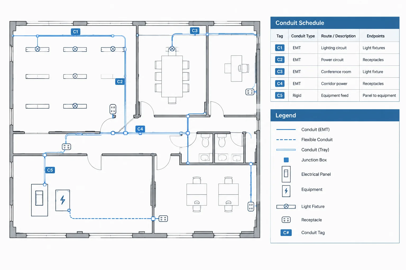
Building an electrical conduit schedule in CAD is primarily an information-management task. The table must connect raceway tags on plans with endpoints, system classifications, route references, and any separately controlled conductor or cable data.
The guidance below focuses on schedule structure, CAD data strategy, drawing coordination, and quality control. It should be adapted to the project’s established terminology, design requirements, and documentation responsibilities.
An electrical conduit schedule organizes raceway information that would be difficult to repeat clearly on every plan, section, and diagram. It can identify each raceway, show where it begins and ends, describe its intended service, and connect routing graphics with conductor or cable documentation.
The schedule is not a substitute for a coordinated electrical design. It is a documentation tool that helps readers trace information across the drawing set. Its value depends on consistent identifiers, controlled data sources, and careful reconciliation with plans, one-line diagrams, details, and related schedules.
When a Conduit Schedule Is Useful
Not every project needs a raceway-by-raceway table. A small plan may be clearer with direct annotations. A conduit schedule becomes more useful when the drawing set contains many tagged routes, repeated pathways, underground runs, equipment interconnections, or areas where long notes would crowd the plan.
Common applications include:
- Site and underground distribution drawings
- Industrial or process equipment connections
- Raceways linking multiple electrical rooms
- Grouped routes shown in trenches, racks, or coordinated corridors
- Projects requiring from-to pathway tracking
- Record drawings where installed route identities must remain traceable
A schedule may cover all identified raceways or only a defined subset. The title, notes, and identifiers should make that boundary clear. For example, a project may schedule major feeders while documenting local branch-circuit raceways through plan notes and circuiting graphics.
Define the Schedule’s Purpose Before Adding Columns
Start by deciding what question the schedule is intended to answer. Is it primarily a routing index, a conductor reference, an installation coordination table, or a record of pathway assignments? Adding every possible field can produce an oversized table that is hard to maintain.
A focused schedule might answer these questions:
- Which raceway is being referenced?
- Where does it originate and terminate?
- What system or service does it support?
- Where is its route shown?
- Where can the reader find associated conductor or cable information?
- Does it have a special status, routing condition, or coordination note?
Confirm which information belongs in the schedule and which belongs elsewhere. Detailed conductor composition may already be controlled by a feeder schedule, cable schedule, panel schedule, or one-line diagram. Repeating the same data in several locations creates additional opportunities for conflicts.
Recommended Conduit Schedule Fields
The exact columns should reflect the project documentation strategy. The following field structure is a practical starting point rather than a universal requirement.
| Field | Purpose | Coordination source |
|---|---|---|
| Raceway ID | Provides the unique reference used on plans and details | Plan tags and project naming rules |
| Origin | Identifies the starting equipment, enclosure, or location | Plans, diagrams, and equipment schedules |
| Destination | Identifies the ending equipment, enclosure, or location | Plans, diagrams, and equipment schedules |
| System or service | Distinguishes power, controls, communications, or another documented use | Drawing discipline and system classification |
| Raceway description | Records the specified type or project designation when required | Design documents and specifications |
| Size reference | Shows the verified raceway size or points to its controlling source | Engineering data and coordinated schedules |
| Contents reference | Links the raceway to conductor, feeder, or cable information | Cable schedules, one-lines, or circuit data |
| Route or sheet reference | Directs the reader to the plan, detail, section, or continuation | Drawing index and cross-references |
| Status | Distinguishes existing, new, spare, future, or other defined conditions | Project status conventions |
| Remarks | Captures concise exceptions that do not fit another field | Project-specific coordination |
Use a separate field for each data category that must be sorted or checked. Combining the origin, destination, status, and remarks in one long description may look compact, but it makes automated review and later updates more difficult.
Create a Stable Raceway Identification System
Each scheduled raceway needs an identifier that can remain stable as drawings develop. The tag should be unique within the stated project scope and should not depend entirely on its location on one sheet. Sheet numbers, room numbers, and equipment names can change during coordination.
A useful identification convention may include a system prefix, route group, area designation, or sequential project identifier. Keep the code short enough to place beside plan linework, but do not make it so compressed that users cannot distinguish similar tags.
Document the convention in the drawing legend, schedule notes, or CAD standards material. If letters, separators, or suffixes carry meaning, define that meaning. Avoid introducing abbreviations that appear nowhere else in the set.
Coordinate Schedule Rows with Plan Graphics
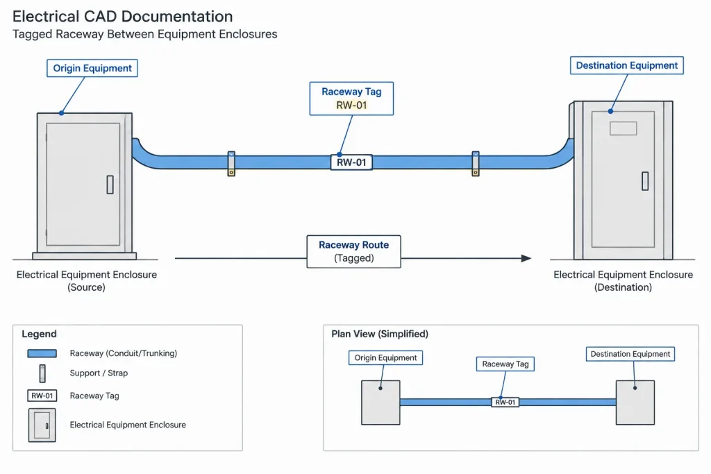
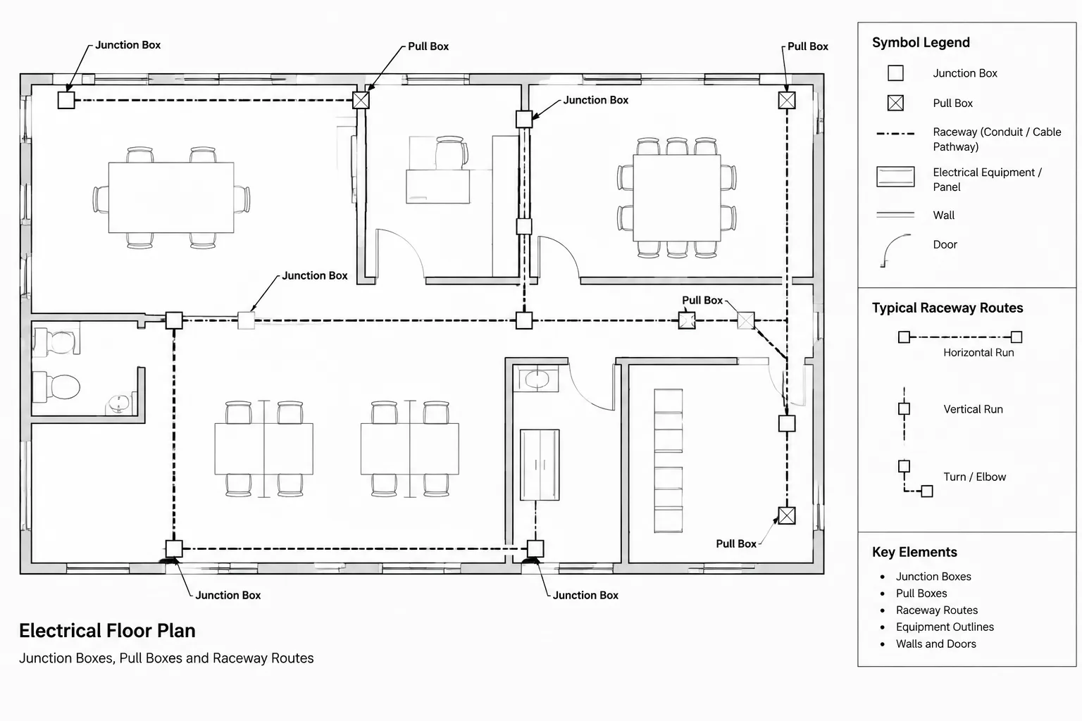
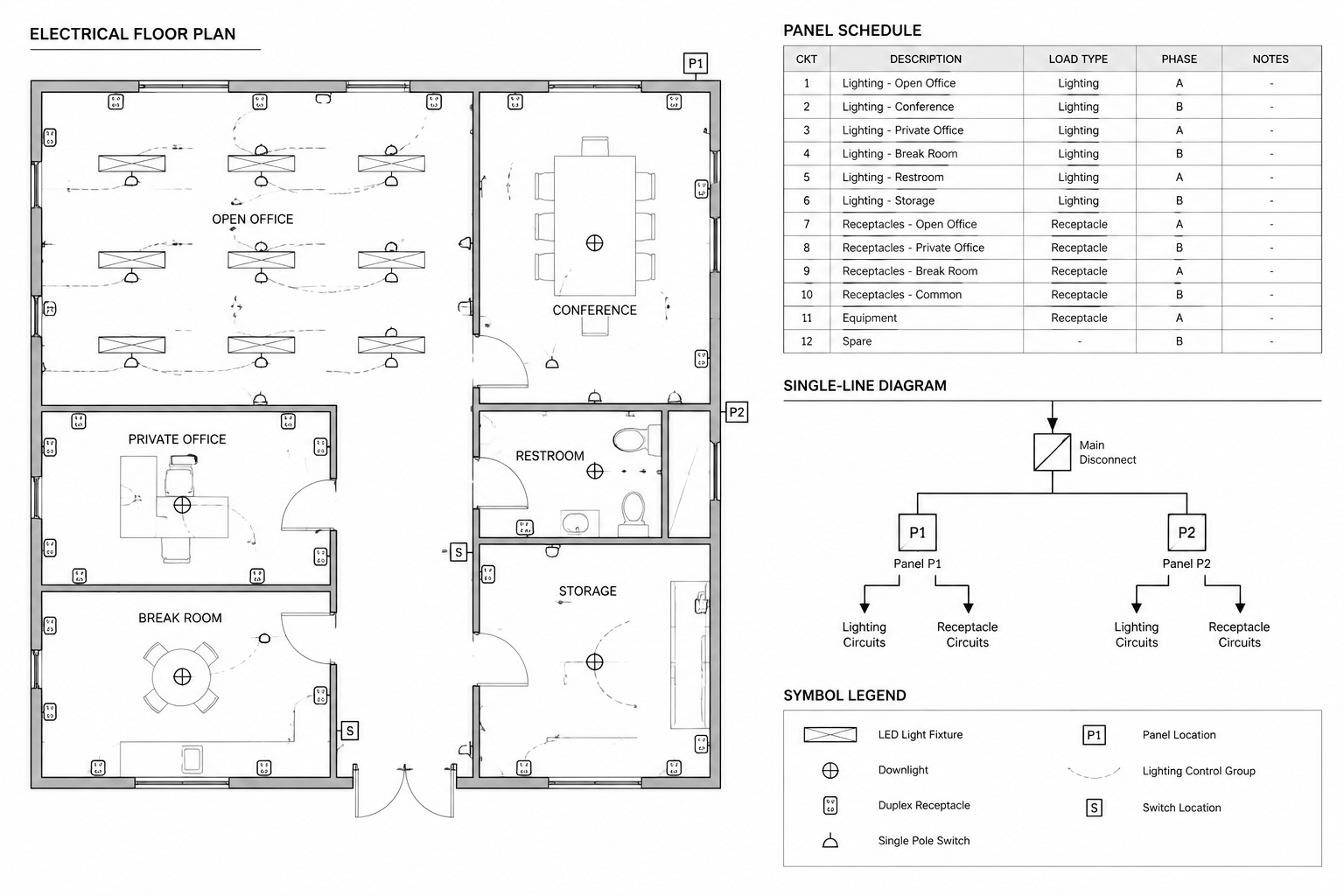
The plan should provide a clear graphic connection between the raceway path and its schedule row. Place the raceway ID near the applicable linework or use a leader when several routes run together. A tag should not appear to identify an adjacent pathway by accident.
Long routes may pass through multiple views or sheets. Repeat the same raceway ID at useful transition points and coordinate it with match lines, continuation notes, or off-sheet references. Do not create a new identifier merely because the route crosses a drawing boundary unless it actually represents a documented change in the pathway.
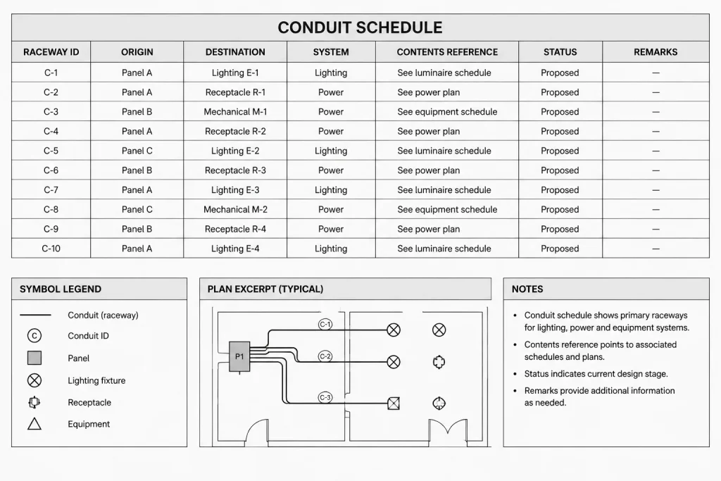
Where a line represents a raceway group rather than one individual conduit, make that graphic convention explicit. The schedule should then identify the members of the group or point to a section or detail that explains the arrangement.
Connect the Schedule to One-Lines and Cable Data
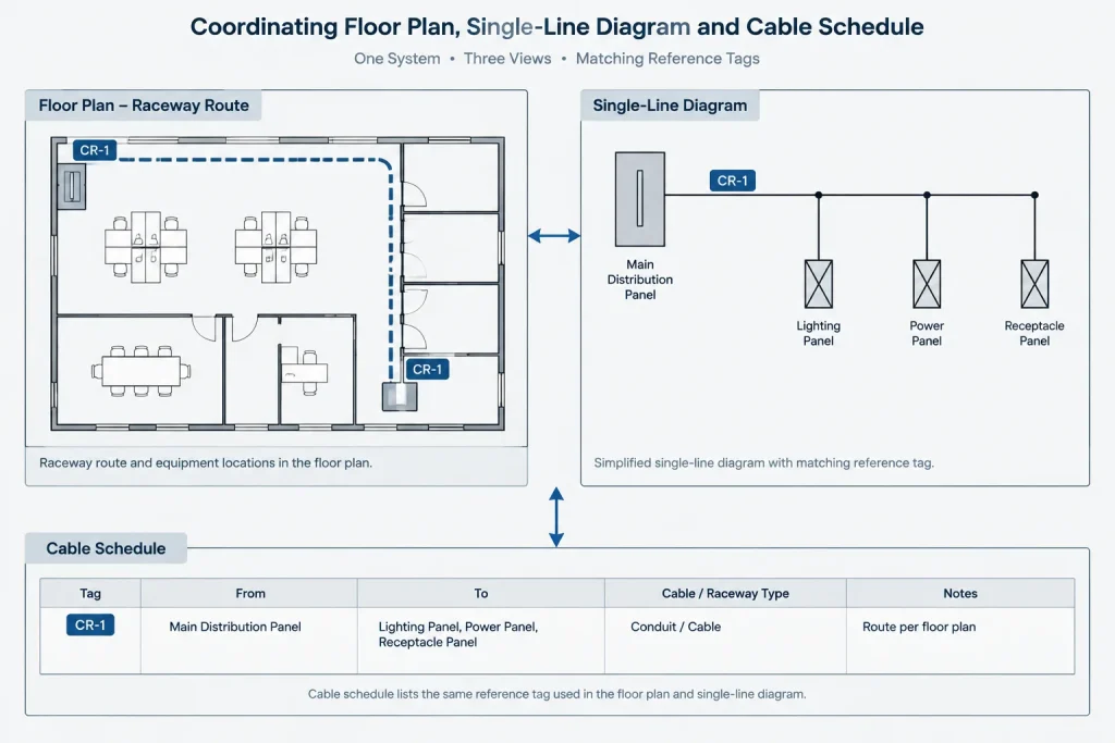
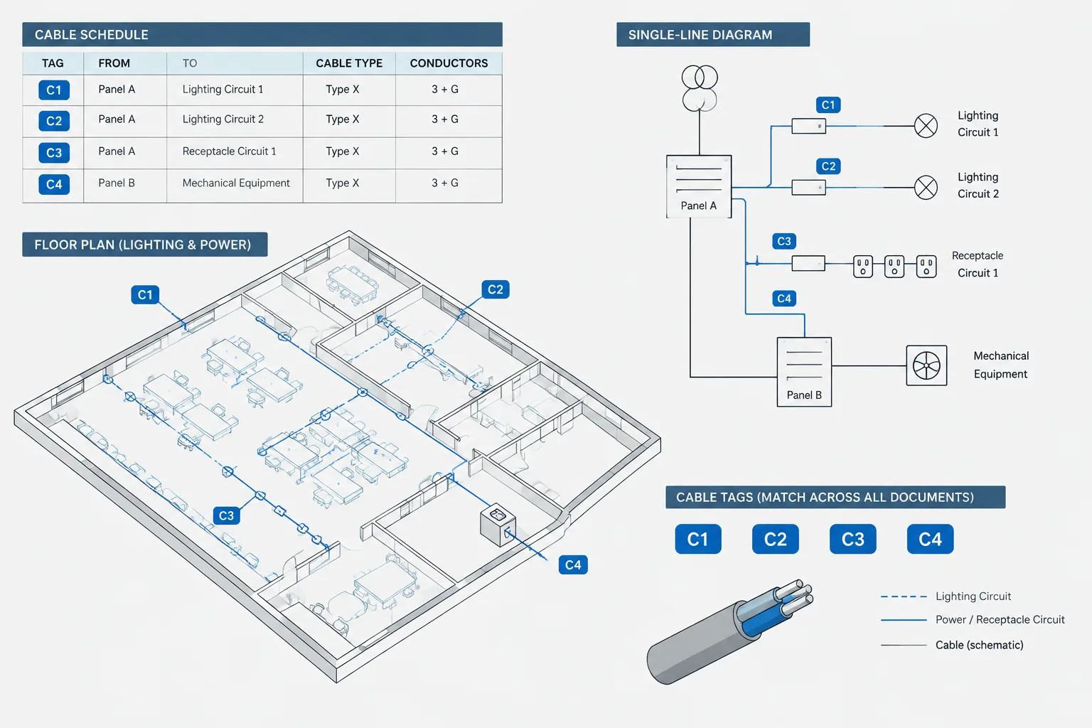
A conduit schedule and a one-line diagram describe different aspects of the same system. The one-line communicates electrical relationships; the conduit schedule tracks physical pathways and endpoints. Their identifiers do not have to be identical, but their references must be unambiguous.
Similarly, distinguish the pathway ID from the cable or feeder ID. One raceway may contain documented conductors or cables with separate identities, while a cable route may pass through more than one scheduled pathway. Dedicated reference fields preserve these relationships without treating the raceway and its contents as the same object.
When information is controlled by another schedule, reference that source rather than copying large data strings. If duplication is necessary for drawing usability, define which location governs updates and include the duplicated fields in the quality-control review.
Choose a CAD Data Strategy
A conduit schedule can be drafted as a conventional CAD table or generated from structured drawing data. The appropriate method depends on project size, team workflow, and deliverable requirements.
Manually Maintained Table
A manual table is straightforward and portable, but every plan change must be entered deliberately. Establish standard text styles, row spacing, column headings, and continuation-sheet formatting. Avoid using loose lines and unrelated text objects when a true table structure is available in the project workflow.
Attribute-Based Workflow
Raceway tags can use block attributes for identifiers and selected schedule fields. Structured attributes can support extraction and checking, but only if the blocks are inserted consistently and attribute definitions remain controlled. Hidden or duplicate tag blocks can contaminate the extracted list.
External Data Workflow
A spreadsheet or database may serve as the managed source for larger schedules. If the CAD table is linked or imported, define who owns the source file, how updates are issued, and how broken paths or stale exports are detected. The plotted sheet must remain reviewable even when the external data source is unavailable to the recipient.
Handle Changes Without Losing Traceability
During design, equipment names, routes, and sheet locations may change. Try to preserve the raceway ID when the documented pathway remains the same. Unnecessary renumbering can disrupt plan tags, review comments, field references, and related schedules.
If a raceway is removed, follow the project’s revision and status procedure rather than silently reusing its identifier for an unrelated route. Reusing old IDs can create ambiguity between previous issue packages and current documents.
For phased or record-drawing work, status should be represented consistently in both the schedule and the plan graphics. Do not rely only on color because plotted output, grayscale reproduction, and external file exchange may remove the distinction.
Conduit Schedule Quality-Control Checklist
Before publishing the drawing set, review the schedule as part of a coordinated package rather than as an isolated table.
- Confirm that every scheduled raceway ID appears where expected on the drawings.
- Search the CAD files for plan tags that have no corresponding schedule row.
- Check for duplicate identifiers assigned to unrelated pathways.
- Verify origin and destination names against current equipment tags.
- Reconcile system classifications with layer, linetype, and legend conventions.
- Check conductor, cable, feeder, and circuit references against their controlling documents.
- Verify that route and sheet references point to current drawing locations.
- Review status terms for consistent use across plans and schedules.
- Check continuation sheets for repeated headings and understandable context.
- Plot the schedule to confirm text, linework, and long remarks remain readable.
A Schedule Should Clarify, Not Duplicate
A well-built electrical conduit schedule gives each important pathway a traceable identity and establishes reliable links between physical routing and system documentation. The most effective schedules are selective: they present the information needed to follow the drawings without copying every note from every related document.
Before using any schedule format on a real project, verify its fields, terminology, raceway data, and cross-references against the project requirements and current design information. CAD structure can improve consistency, but it does not replace technical review.
Practical CAD Workflow Considerations
Before drafting the schedule, identify the authoritative source for each field. Equipment names may come from equipment schedules, pathway identifiers may be controlled by plan tags, and cable information may be maintained in a separate dataset. Recording these ownership relationships helps prevent conflicting edits.
Use CAD objects that support the intended review process. A visually correct table may still be difficult to audit if its content consists of disconnected text and linework. Structured tables, controlled block attributes, or managed external data can make filtering and comparison easier, provided the team follows a consistent update procedure.
Separate Data from Presentation
The underlying schedule data and its plotted appearance serve different purposes. Data fields should remain consistent enough to sort, compare, and validate, while the sheet presentation should remain readable within the drawing set. Avoid placing critical information only in merged headings, graphic symbols, or formatting that will be lost during extraction.
Plan for Issue and Revision Reviews
At each drawing issue, compare the schedule against the current plan tags and related documentation. Review added, removed, and changed pathways rather than checking only the final appearance of the table. This change-focused review can reveal stale rows, reused identifiers, and references that still point to superseded drawing locations.
Test the Recipient’s View
Review the schedule from the perspective of someone who does not have access to the authoring database or the drafter’s working notes. The plotted drawing should clearly communicate identifiers, endpoints, status, and cross-references without depending on hidden attributes, unsupported links, or color alone.
Common Documentation Problems to Avoid
- Unscheduled plan tags: A raceway identifier appears on a plan but has no matching table entry.
- Orphaned schedule rows: A listed pathway no longer appears in the drawing set.
- Mixed naming conventions: Equipment or location names differ between plans, diagrams, and schedules.
- Overloaded remarks: Important data is buried in free-form notes instead of placed in a defined field.
- Unclear data ownership: The same information is edited independently in several documents.
- Graphic-only status: Existing, new, spare, or future conditions are distinguishable only by color or visual styling.
- Stale external data: The plotted schedule does not reflect the current managed source.
A conduit schedule is most dependable when its identifiers, sources, and review responsibilities are established before the table grows. Final content should always be checked against the current coordinated electrical design and project documentation requirements.
Frequently Asked Questions
What is the difference between a conduit schedule and a cable schedule?
A conduit schedule documents physical pathways and their endpoints. A cable schedule documents the cables assigned to the design. The two may reference each other, but a pathway identifier should not automatically be treated as a cable identifier.
Should every conduit shown on a plan be scheduled?
Not necessarily. The schedule scope should follow the project’s documentation strategy. Clearly define whether the table covers all tagged raceways or only selected pathways, such as major routes or grouped runs.
Can a conduit schedule be created from CAD block attributes?
Yes. Attribute-based tags can support data extraction when block definitions, field names, and insertion practices are controlled. The extracted results still require checks for duplicate, hidden, outdated, or incorrectly placed blocks.
Should conductor information be repeated in the conduit schedule?
Repeat it only when that approach supports the project workflow. If another schedule or diagram controls the conductor data, a clear reference may be safer than maintaining duplicate descriptions in multiple locations.
How should a route crossing several sheets be documented?
Keep the pathway identity consistent and use coordinated continuation or drawing references. A sheet boundary alone does not necessarily justify creating a different raceway identifier.
What should happen when a scheduled pathway is deleted?
Follow the project’s revision and record-management procedure. Avoid assigning its identifier to an unrelated pathway when that reuse could confuse earlier drawing issues, review comments, or record documentation.
Leave a Reply
You must be logged in to post a comment.