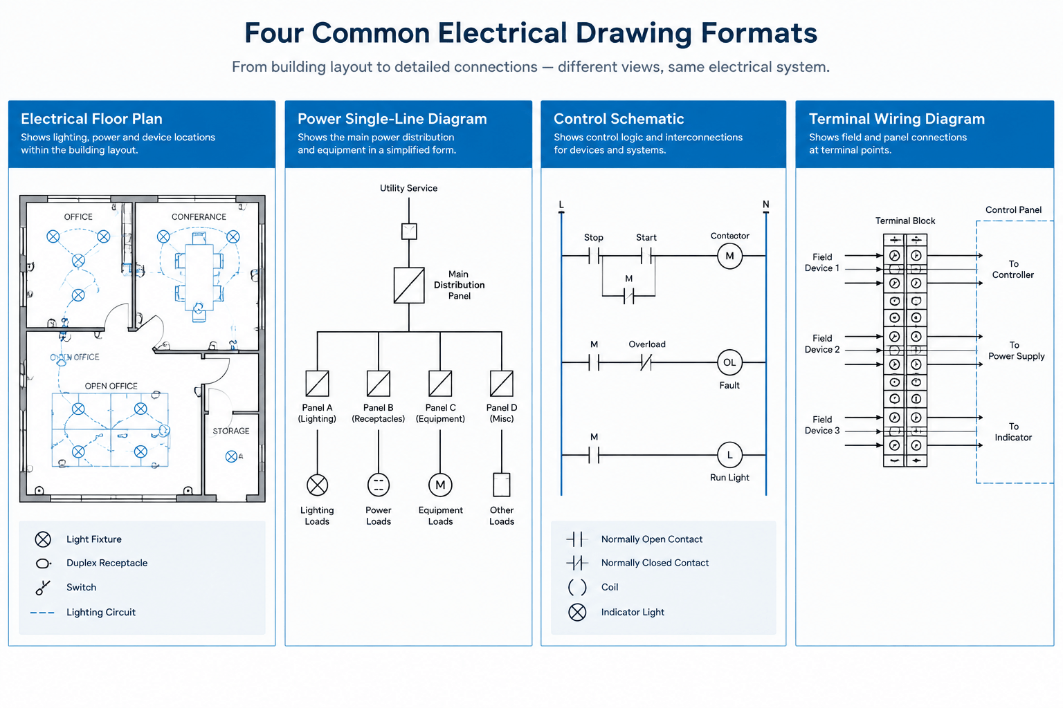
An electrical floor plan, single-line diagram, schematic, and wiring diagram can describe the same project from very different viewpoints. Treating them as interchangeable often produces crowded sheets, inconsistent equipment tags, or details that do not answer the installer’s and reviewer’s questions.
The distinction is not simply graphical. Each drawing type has a particular communication purpose. A floor plan emphasizes location, a single-line diagram emphasizes distribution relationships, a schematic emphasizes functional logic, and a wiring diagram emphasizes conductors and terminations. Understanding these roles helps CAD users select appropriate symbols, references, layers, and levels of detail.
Quick comparison of electrical drawing types
| Drawing type | Primary question answered | Typical information | Usually not intended to show |
|---|---|---|---|
| Electrical plan | Where is it located? | Devices, equipment, circuit references, routing indications, room relationships, and mounting notes | Every internal connection or complete distribution logic |
| Single-line diagram | How is power distributed? | Sources, feeders, protective devices, transformers, switchboards, panels, major loads, and system relationships | Physical conductor arrangement or precise plan location |
| Schematic diagram | How does the circuit function? | Logical connections, contacts, coils, control devices, interlocks, and operating relationships | Actual equipment placement or terminal-by-terminal field routing |
| Wiring diagram | How are components connected? | Conductors, terminals, cables, connection points, and equipment interfaces | Building-wide spatial coordination unless specifically developed for that purpose |
These descriptions reflect common drafting practice rather than universal naming rules. Project specifications, client standards, and discipline conventions may define the terms differently. The drawing title and legend should make the intended meaning clear.
Electrical floor plans: documenting physical location
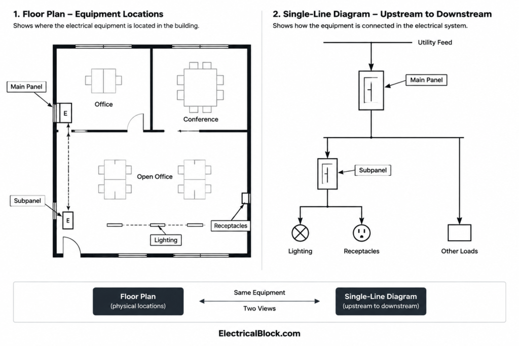
An electrical plan is normally built over an architectural or site background. It shows where electrical items relate to walls, doors, ceilings, furniture, equipment, and other constructed features. Depending on the sheet purpose, it may document lighting, receptacles, equipment power connections, communications devices, security devices, or routing.
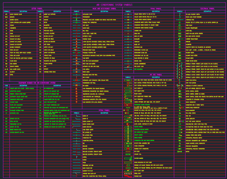
Plan symbols are often simplified because the drawing must remain readable at its plotted scale. A receptacle symbol, for example, communicates a device type and approximate placement rather than the physical shape of a specific product. Tags, keynotes, circuit references, schedules, and details carry information that would be too dense to place directly beside the symbol.
Useful CAD content on a plan
- Device and equipment symbols positioned against a coordinated background
- Unique tags that connect equipment to schedules and diagrams
- Panel and circuit references where required by the documentation method
- Home-run, conduit, cable tray, or underground routing indications when part of the drawing scope
- Mounting, accessibility, or location notes that cannot be inferred from the symbol
- Detail, section, and enlarged-plan callouts for areas requiring more explanation
A floor plan should not be forced to explain every electrical relationship. If a device’s source, feeder path, or control logic is difficult to understand in plan view, reference a diagram or detail rather than building a miniature schematic into the plan.
Single-line diagrams: simplifying power distribution
A single-line diagram, also called a one-line diagram, represents a power distribution system with simplified lines and symbols. One graphic line can stand for a multi-conductor circuit or feeder. The objective is to explain the hierarchy and connectivity of the system without drawing each conductor individually.
A one-line commonly progresses from a source toward downstream distribution equipment and loads. It can show how switchgear, switchboards, transformers, panelboards, transfer equipment, generators, and major utilization equipment relate to one another. Project-specific annotations may identify feeders, overcurrent devices, equipment names, grounding relationships, or other design information.
Unlike a floor plan, the arrangement is diagrammatic. Equipment placed beside another item on the one-line is not necessarily beside it in the building. Physical location belongs on plans, room layouts, sections, or equipment elevations.
Drafting priorities for a clear one-line
- Maintain an obvious upstream-to-downstream reading direction.
- Use consistent equipment symbols and tag formats.
- Separate normal, alternate, emergency, or other distribution paths graphically when the project requires them.
- Avoid line crossings where rerouting or continuation references would be clearer.
- Keep repeated annotation in schedules or notes when that reduces clutter without hiding essential relationships.
- Coordinate every named panel and major equipment item with the plans and schedules.
A one-line symbol should be treated as a diagram component, not automatically reused as a plan symbol. The two may represent the same equipment but require different graphics because they answer different questions.
Schematic diagrams: explaining circuit behavior
A schematic shows functional electrical relationships. Components are arranged to make operation understandable rather than to reproduce their physical positions. This format is common for control circuits, relay logic, motor controls, alarms, interlocks, and sequences involving contacts, switches, sensors, and coils.
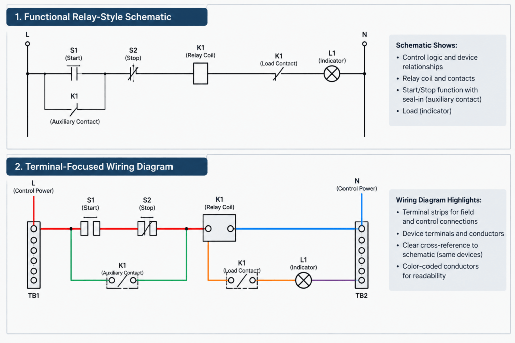
In a schematic, the relationship between contacts and their associated device is critical. Cross-references, device designations, wire references, and continuation markers may be needed when related elements are separated across the sheet or drawing set. A physically compact assembly can occupy a large schematic area if that improves comprehension.
Drafting should favor a predictable logical flow. Signal or control paths should be easy to trace, and connection dots must be visually distinct from simple line crossings. Similar-looking symbols should not depend on tiny differences that disappear when plotted.
Wiring diagrams: showing connection details
A wiring diagram focuses on how components are interconnected. It may identify terminals, cables, conductor references, connectors, junction points, and interfaces between assemblies. Some wiring diagrams are highly diagrammatic, while others resemble equipment layouts with connection lines added.
The term can describe several deliverables, so the title should be specific. A terminal wiring diagram, interconnection diagram, point-to-point diagram, and equipment wiring detail may each present different levels of information. A generic title such as “wiring” can leave users uncertain about whether the drawing represents design intent, fabrication information, or field connections.
Connection information should be based on verified project and manufacturer documentation. A typical CAD block or library symbol does not establish terminal assignments, internal product wiring, conductor requirements, or suitability for a particular installation.
How the drawings coordinate
The four formats work best as a connected documentation system. Consider a panel supplying a piece of mechanical equipment:
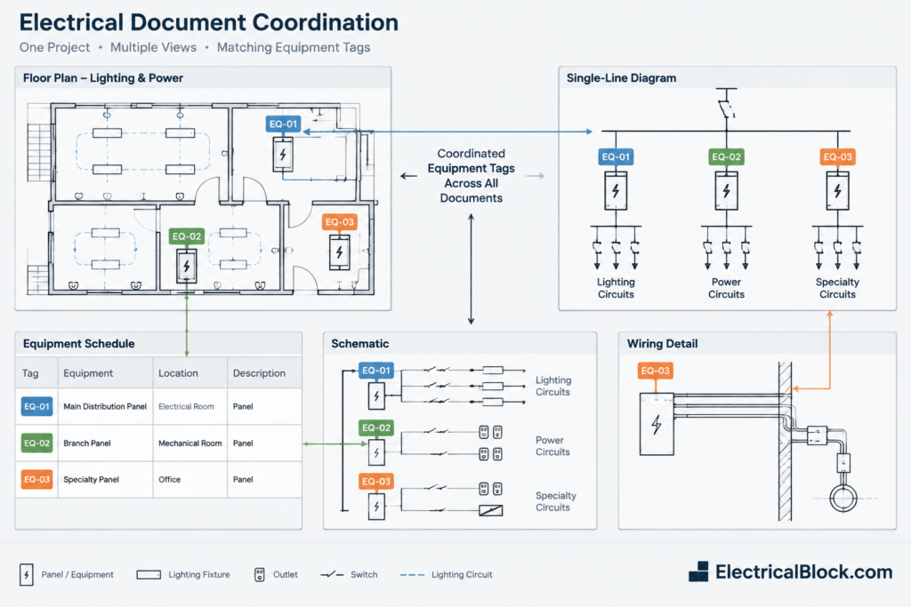
- The floor plan shows where the panel and equipment are located.
- The single-line diagram shows the panel’s place in the distribution hierarchy.
- A schematic may explain the control or interlock sequence.
- A wiring diagram may identify the interfaces and terminations between control components.
The equipment tag is the link between these views. If a tag changes on one drawing, it should be checked everywhere it appears, including schedules, details, notes, and calculations maintained outside CAD. The same principle applies to source names, circuit references, and drawing callouts.
Choosing the correct CAD block
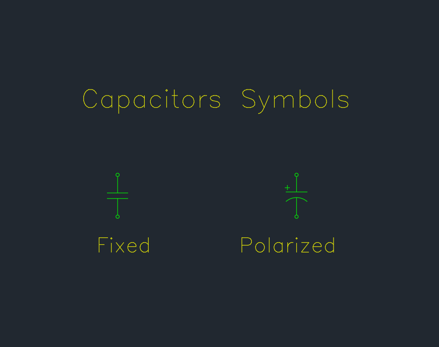
Before inserting a block, determine what the drawing must communicate. A realistic equipment footprint may be useful on a room layout but distracting on a one-line. A compact schematic symbol may work well in a control diagram but provide no meaningful clearance or orientation information on a floor plan.
Evaluate library content using these questions:
- Was the block created for a plan, diagram, elevation, or detail?
- Does its visual complexity suit the intended plot scale?
- Are its attributes compatible with the project’s tag structure?
- Does it rely on colors, lineweights, or fonts that conflict with the drawing standard?
- Is it generic, or does it imply unverified product-specific information?
- Will it remain legible when placed among other symbols and annotations?
Library blocks are drafting resources, not design approvals. Their geometry, annotations, and technical meaning should be reviewed before use on a real project.
A practical cross-drawing review workflow
- Start with identifiers. Compare equipment and device tags across plans, diagrams, and schedules.
- Trace sources and destinations. Confirm that loads shown on plans can be located on the applicable distribution drawing.
- Review drawing roles. Remove misplaced information that obscures the main purpose of a sheet, while preserving necessary references.
- Check references. Verify continuation notes, detail callouts, sheet references, and schematic cross-references.
- Inspect plotted output. Confirm that symbols, junction markers, lines, and text remain distinguishable in the issued format.
- Resolve conflicts deliberately. Do not assume one drawing automatically overrides another; follow the project’s document-control process.
Final drafting principle
The best electrical drawing is not the one containing the most information. It is the one that answers its intended question clearly and directs the reader to related information without contradiction. Use plans for location, single-line diagrams for distribution, schematics for function, and wiring diagrams for connections. Coordinated tags and references then turn those individual views into a usable electrical document set.





Leave a Reply
You must be logged in to post a comment.