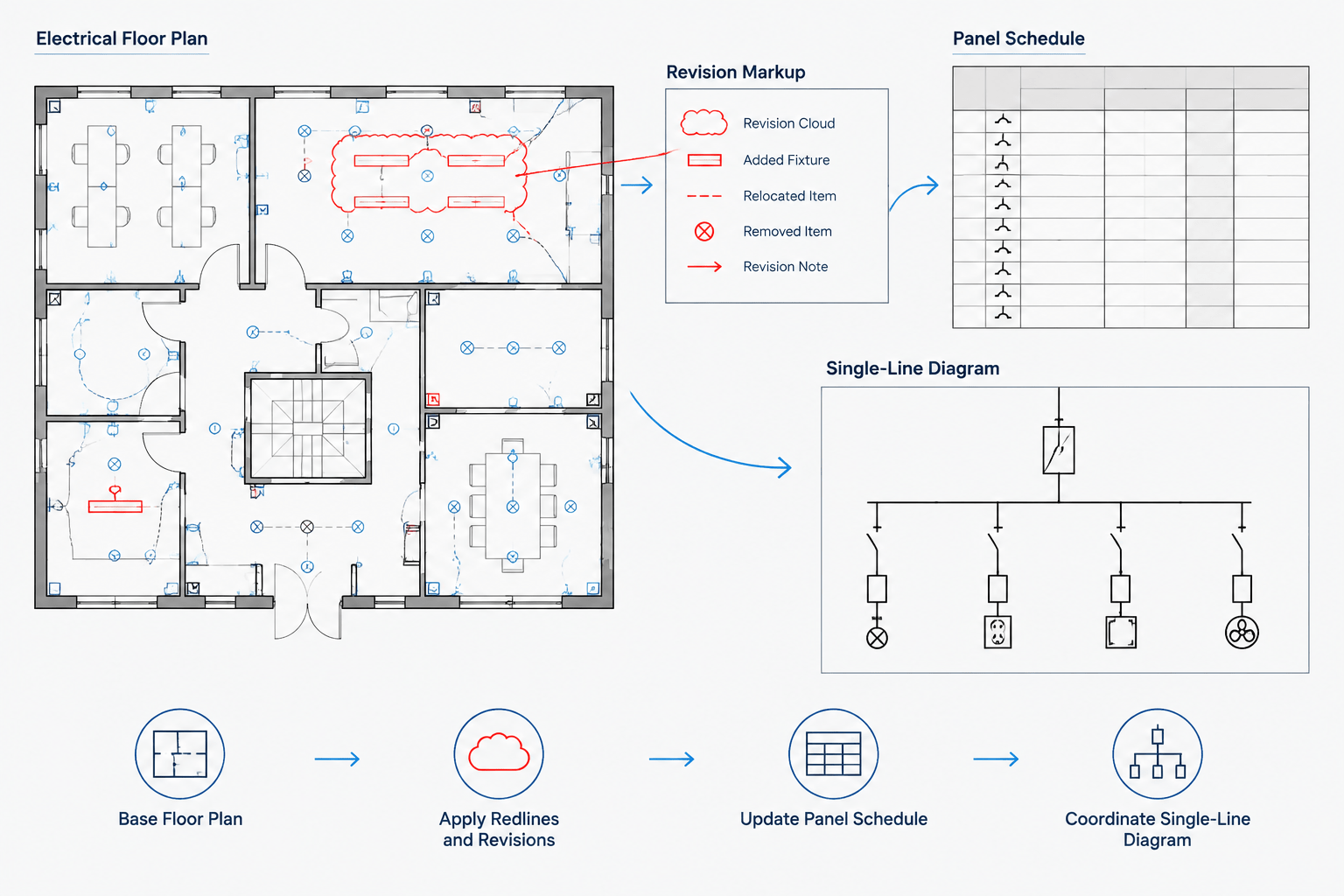
An electrical drawing revision is more than a collection of edited lines and symbols. A change made on a power plan may also affect a panel schedule, single-line diagram, equipment layout, detail, legend, or another discipline’s background. Without a controlled process, a seemingly minor update can create contradictions across the drawing set.
A reliable electrical drawing revision workflow connects the original request, marked-up source, CAD edits, coordination checks, and final issue record. The goal is not merely to make the drawing look current. It is to preserve design intent, show reviewers what changed, and prevent outdated information from remaining elsewhere in the documents.
Start by Identifying the Revision Source
Before editing CAD files, determine where the requested change came from and what authority it carries. Revision inputs may include design-team redlines, coordination comments, review responses, equipment-submittal information, owner requests, or verified field observations.
These sources are not automatically interchangeable. A handwritten field note, for example, should not be treated as final design direction unless the project’s responsible reviewers have accepted it. Record the origin of each markup and keep unresolved comments separate from approved changes.
A useful markup should communicate
- The sheet, view, detail, or schedule affected.
- The object or system being revised.
- Whether geometry, annotation, connectivity, or identification must change.
- Related drawings that may also require review.
- The person or team responsible for resolving an open question.
Ambiguous instructions such as “move this” or “revise circuit” should be clarified before production. Guessing may produce a polished drawing that communicates the wrong design.
Build a Change-Impact List Before Editing
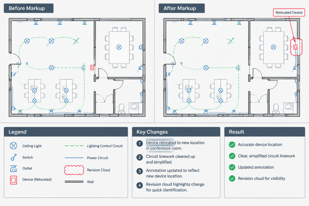
Electrical information is repeated intentionally in different forms. A device may appear as a plan symbol, connect to a circuit annotation, be listed in a schedule, and be represented in a distribution diagram. The drafter should therefore evaluate each revision as a relationship rather than an isolated graphic edit.
| Plan change | Related documents to review |
|---|---|
| Device added, removed, or relocated | Plan notes, circuiting, schedules, details, equipment clearances, and legends |
| Panel designation changed | Panel schedules, feeders, single-line diagrams, risers, tags, and references |
| Lighting control intent revised | Lighting plan, control diagram, sequence notes, device tags, and room references |
| Equipment connection revised | Power plan, equipment schedule, connection detail, circuit information, and mechanical coordination |
| Cable or conduit route revised | Pathway plans, sections, details, pull or junction points, and coordination views |
This change-impact list can be created as a simple project checklist. Its value comes from forcing the team to ask where the same information appears elsewhere.
Preserve a Traceable Working Record
Do not erase the history of a change before it has been reviewed. Retain the source markup in the project’s controlled document location and use a working copy of the CAD file under the project’s file-management rules. The team should be able to determine what was requested, what was changed, and which drawing issue contains the result.
A controlled workflow also prevents multiple drafters from unknowingly editing different copies of the same sheet. File naming, access permissions, check-in procedures, and issue folders should follow the project’s established document-control system rather than personal desktop habits.
Revise the CAD Content Without Breaking Its Structure
Electrical revisions should respect the drawing’s existing organization. Before editing, inspect layers, blocks, external references, annotation styles, sheet references, and plotting behavior. An imported symbol or copied note may look correct on screen while behaving incorrectly in the issued file.
Review these CAD elements during production
- Layers: Place revised objects on the appropriate project layers instead of creating near-duplicate layer names.
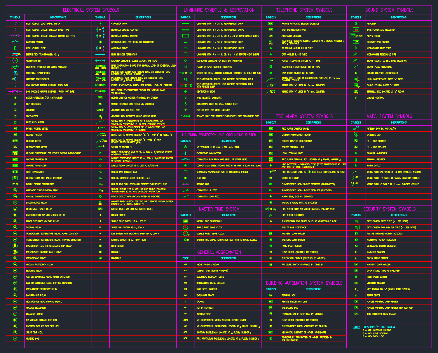
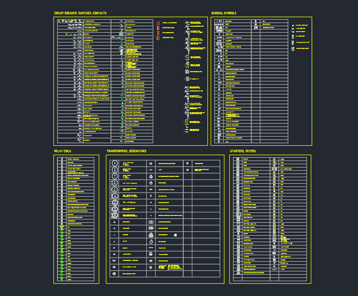
- Blocks: Confirm that symbols use the intended insertion point, orientation, attributes, and graphic convention.
- External references: Determine whether the change belongs in the electrical file or in a referenced architectural or engineering background.
- Text and tags: Match established annotation hierarchy and avoid manually overriding information that should remain coordinated.
- Linework: Remove abandoned segments, disconnected leaders, duplicate geometry, and obsolete route fragments.
- Sheet composition: Check whether added notes or symbols interfere with match lines, view titles, schedules, or plotted margins.
If a library block does not match the project’s legend or drafting convention, adapt it through the project’s approved content process. A downloaded CAD block should never be assumed to be project-ready merely because its geometry is clean.
Separate Design Revisions from Background Updates
Architectural backgrounds often change during design. A shifted wall, renamed room, or revised ceiling arrangement may cause electrical symbols to appear incorrectly located even when the electrical design decision has not changed.
When reloading or replacing a background, compare the old and new conditions deliberately. Look for devices left outside rooms, lighting symbols no longer aligned with ceiling elements, equipment connections separated from their equipment, and annotations obscured by new geometry. Do not move electrical content solely to improve appearance if the relocation would alter design intent.
Where a background change creates a genuine design question, mark it for coordination rather than silently resolving it through drafting.
Coordinate Plans, Schedules, and Diagrams
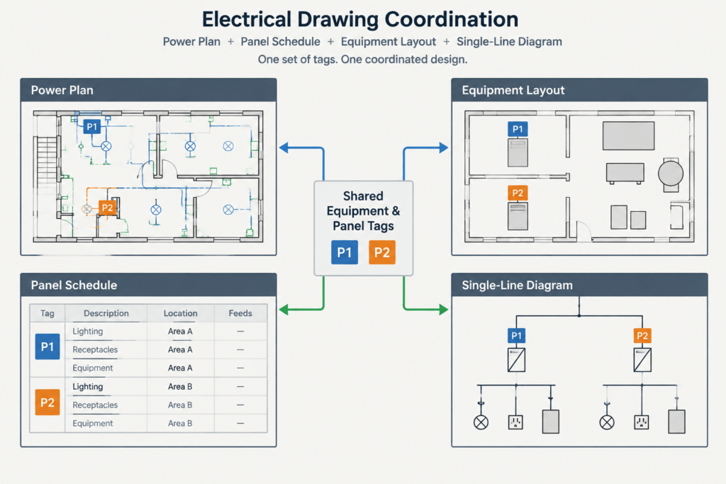
Cross-document coordination is the central quality check in an electrical revision workflow. Start with identifiers because they link otherwise different drawing types. Panel names, equipment tags, circuit references, feeder labels, detail numbers, and room names should lead a reviewer to consistent information.
Next, review system logic. If a branch circuit is reassigned on a plan, verify that its schedule representation remains consistent. If distribution equipment changes, follow the documented path through the applicable diagram and downstream references. If a detail callout is moved or replaced, confirm that the referenced detail still describes the condition shown.
Coordination does not mean every drawing must repeat every fact. It means that repeated information should agree and that references should lead to the correct source.
Use Revision Graphics Carefully
Revision clouds, markers, and revision entries help readers find changes in a particular issue. They are communication devices, not substitutes for complete editing. A cloud around a changed symbol will not alert a reviewer to an uncorrected schedule on another sheet.
Apply revision graphics according to the project’s documentation requirements. Keep clouds specific enough to identify the affected area without obscuring unrelated content. Confirm that the revision identifier agrees with the sheet record and issue documentation. Before a later issue, determine whether previous revision graphics should remain, be removed, or be archived under the project’s established procedure.
Perform a Structured Quality-Control Pass
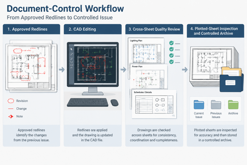
A useful review moves from broad document control to detailed graphics. Reviewing only at high zoom can hide sheet-level problems, while reviewing only the plotted sheet can miss disconnected or duplicated CAD objects.
Suggested review sequence
- Confirm that the correct files, backgrounds, and sheet versions are open.
- Compare each completed change against its source markup.
- Check related sheets identified in the change-impact list.
- Review identifiers, references, schedules, legends, and diagram relationships.
- Inspect revised areas for stray geometry, overlapping text, broken leaders, and incorrect layers.
- Generate the intended output and review its plotted appearance.
- Verify revision entries and issue information.
- Have a reviewer who did not perform the edit examine significant changes when the project process allows.
Closeout should include a disposition for every markup: completed, superseded, clarified, rejected, or still open. This prevents unanswered comments from disappearing into an apparently finished set.
Record Drawings Require Additional Caution
Terms such as record drawing and as-built drawing may carry different contractual meanings. A CAD file updated from field markups should not be presented as independently verified unless the project process actually includes that verification.
Keep observed conditions, contractor-provided information, and designer-directed changes distinguishable in the documentation trail. Drafting staff can accurately incorporate authorized information, but the drawing status must be determined by the responsible project parties.
A Good Revision Workflow Protects Drawing Relationships
The strongest electrical revision process is built around traceability and coordination. It begins with an authorized, understandable markup; identifies every affected representation; preserves CAD structure; checks related documents; and finishes with a controlled issue record.
This approach takes more discipline than editing only the circled area, but it produces drawings that are easier to review, maintain, and use. Most importantly, it reduces the risk that two parts of the same electrical drawing set will communicate different design information.




Leave a Reply
You must be logged in to post a comment.