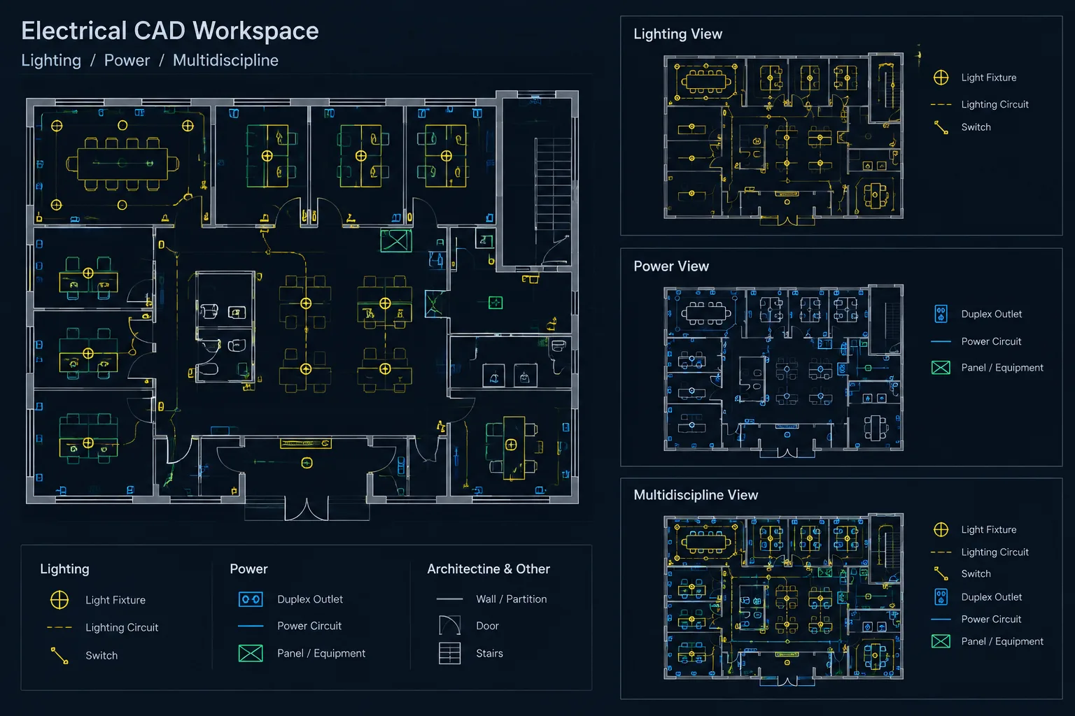
Electrical CAD layer states help separate presentation from source geometry. Instead of copying a coordinated plan to create lighting, power, specialty-system, and review drawings, a drafting team can preserve shared objects and apply controlled visibility for each intended view.
This approach works best when layer organization, viewport behavior, annotation ownership, and plotting checks are planned together. The guidance below explains how to structure those decisions while recognizing that commands and saved properties differ among CAD applications.
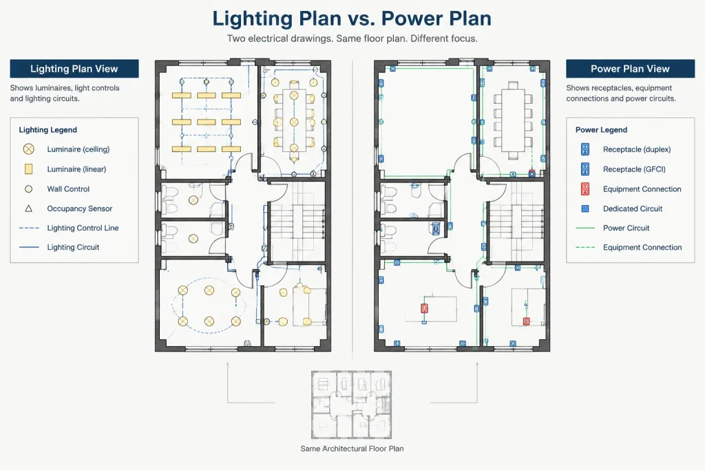
Electrical floor plans often share the same architectural background, room layout, equipment locations, and portions of the electrical design. Yet each sheet must emphasize a different scope. A lighting plan may need luminaires and controls, while a power plan highlights receptacles, equipment connections, and circuiting. Communications or security plans may require another combination of symbols and annotations.
Duplicating the entire floor plan for every discipline view can create coordination problems. A device moved on one copy may remain unchanged on another. Room revisions may be incorporated inconsistently, and repeated geometry can make the drawing file harder to manage. Electrical CAD layer states and related visibility controls offer a more reliable approach: maintain coordinated source geometry, then control what appears in each drawing view.
The exact names of visibility tools vary among CAD platforms, but the underlying drafting principle is consistent. Separate information by purpose, define repeatable display conditions, and verify every plotted sheet rather than treating the current model view as the final deliverable.
What an Electrical CAD Layer State Controls
A layer state is a saved collection of layer display properties. Depending on the CAD application and project workflow, it may record whether layers are visible, frozen, locked, plotted, or displayed with particular colors, linetypes, transparency settings, or lineweights.
For electrical documentation, a layer state can establish the intended view for a particular task or plan type. Examples include:
- A lighting plan showing luminaires, switching, lighting controls, circuit annotations, and selected ceiling information.
- A power plan showing receptacles, equipment connections, branch-circuit graphics, and relevant architectural references.
- A coordination view displaying several electrical systems together for internal review.
- A background review view that makes architectural or consultant layers more prominent.
- A plotting view that suppresses construction lines, temporary markups, and nonprinting coordination information.
A layer state does not determine whether the electrical design is correct. It only manages how stored drawing information is presented. Designers and drafters must still confirm scope, circuit relationships, equipment data, sheet references, and project requirements.
Why Duplicate Geometry Becomes a Documentation Risk
Copying a floor plan may appear convenient at the beginning of a project, especially when plan types look substantially different. The problem becomes visible after revisions begin. If the same panel, receptacle, equipment connection, or room outline exists in several independent copies, every change must be found and repeated.
Common consequences include:
- Devices appearing in different locations on related sheets.
- Old room names or equipment references remaining on one plan.
- Circuit tags disagreeing between plan copies.
- Demolition information accidentally appearing in new-work views.
- Symbols being deleted from one copy but retained elsewhere.
- Review comments being applied to only one representation of the same item.
Visibility-based documentation reduces these risks by allowing a single coordinated object to support more than one view when appropriate. It does not mean that every sheet must display the same geometry. It means that shared information should not be copied merely to obtain a different visual presentation.
Build the Layer Structure Before Saving Views
Useful layer states depend on useful layer organization. If lighting fixtures, receptacles, control devices, and circuit lines all occupy one general electrical layer, visibility controls cannot separate them cleanly.
Organize layers around meaningful documentation categories. A project may distinguish among:
- Lighting fixtures and associated tags.
- Lighting control devices and control relationships.
- Power devices and receptacles.
- Equipment connections.
- Branch-circuit lines, home runs, and circuit annotations.
- Panels, transformers, disconnects, and other distribution equipment.
- Communications, security, or specialty-system content.
- Existing, demolition, new, and future work where project scope requires status separation.
- Electrical text, dimensions, match lines, and detail callouts.
- Architectural, structural, mechanical, and civil references.
The goal is not to create the largest possible layer list. The goal is to provide enough separation for plotting, coordination, editing, and quality control. Layer names should follow the project’s documented CAD convention rather than an improvised personal system.
A Practical Workflow for Plan-Type Visibility
1. Identify the required drawing views
Start with the sheet list and documentation strategy. Determine which floor-plan views are required and what each must communicate. A plan type should exist because it serves a clear documentation purpose, not simply because a previous project used it.
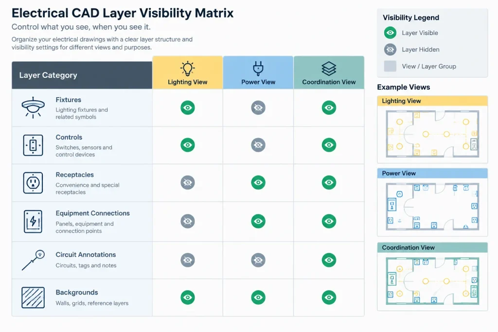
2. Create a visibility matrix
Before configuring the CAD file, make a simple matrix showing which content categories belong in each view. This reveals conflicts early and helps the team decide whether information should be hidden, screened, emphasized, or moved to another sheet.
| Content category | Lighting plan | Power plan | Coordination view |
|---|---|---|---|
| Lighting fixtures | Primary | Hidden or reference only | Visible |
| Lighting controls | Primary | Usually hidden | Visible |
| Receptacles | Usually hidden | Primary | Visible |
| Equipment connections | As relevant | Primary | Visible |
| Circuit annotations | Plan-specific | Plan-specific | Optional |
| Architectural background | Reference | Reference | Reference |
This matrix is an editorial example, not a universal plotting rule. Actual visibility should follow project scope and office standards.
3. Assign objects to layers by function
Review blocks, lines, hatches, and annotation before saving layer states. Pay particular attention to blocks whose internal objects reside on unexpected layers. A symbol inserted on a lighting layer may still contain nested geometry assigned to a different layer, causing part of it to remain visible when the parent layer is hidden.
Also check text and leaders. A device can disappear correctly while its tag remains visible if the symbol and annotation use separate layers without coordinated visibility rules.
4. Save clearly named states
Use names that communicate purpose, such as a lighting working view, power plotting view, or multidisciplinary coordination view. Avoid vague labels such as “State 1” or “Final,” which provide little guidance and become misleading after later issues.
If working and plotting displays differ, identify that difference explicitly. A working state may show reference layers or temporary coordination graphics that should not appear in the issued sheet.
5. Apply visibility at the correct level
CAD environments may allow visibility to be controlled globally, within individual viewports, or through other view-specific settings. Select the method intentionally. A global change can affect every view using the model, while viewport-specific control can allow the same source geometry to appear differently on separate sheets.
Document which method the project uses. Mixing global layer changes and viewport overrides without a clear strategy can make display problems difficult to diagnose.
6. Test every sheet in its plotted context
Do not evaluate visibility only while editing model geometry. Inspect the sheet viewport at its intended scale and produce a test plot or PDF. Confirm that symbols remain recognizable, annotation is complete, backgrounds have suitable visual hierarchy, and hidden systems have not left unexplained tags or circuit lines behind.
Handle Circuiting and Annotation Carefully
Symbols are usually easier to separate than circuit graphics. A circuit line may connect several devices, cross a match line, or share a home-run annotation with related objects. Hiding one device category without reviewing the circuit layer can leave an incomplete line or a floating circuit tag.
Decide whether circuiting is specific to each plan type or belongs in a shared layer group. Where a circuit serves content shown on different plans, the drawing may require separate explanatory graphics or references rather than one line displayed everywhere.
General notes, keynotes, and detail callouts also require plan-specific review. Hiding a symbol does not automatically remove a note that refers to it. Visibility controls should therefore be treated as part of the documentation workflow, not as a substitute for sheet editing.
Use a Coordination View for Quality Control
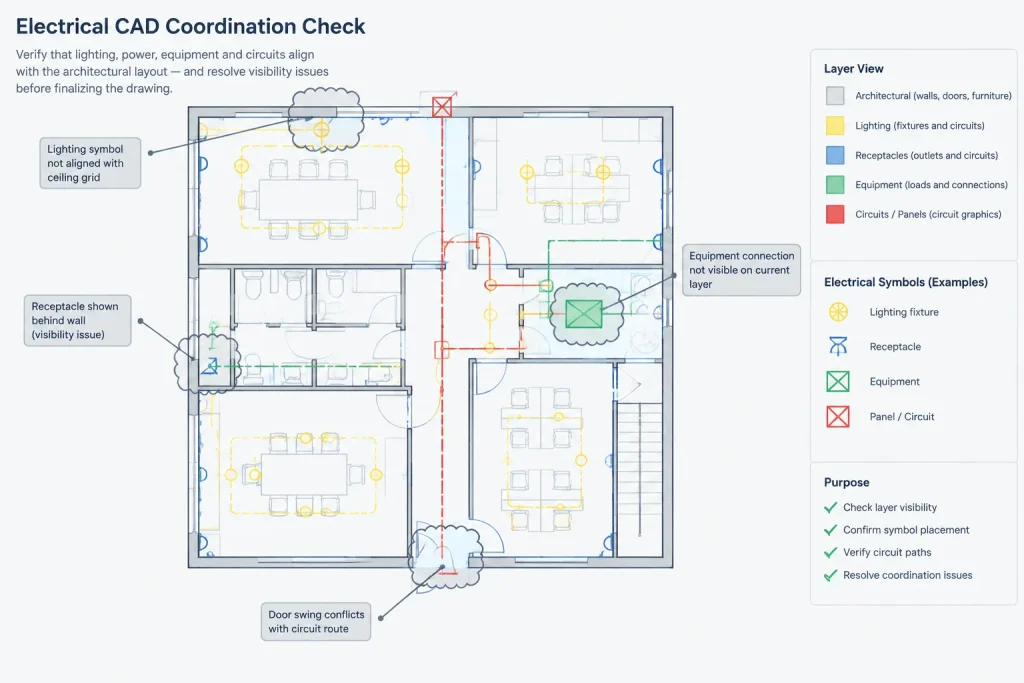
A dedicated coordination state can show multiple electrical systems at once, even if no issued sheet displays them together. This view helps reviewers identify overlapping symbols, equipment conflicts, duplicate devices, inconsistent tags, and routing congestion.
It can also make omissions easier to spot. For example, a mechanical equipment item visible in the background may have an associated power connection but no corresponding disconnect symbol or circuit reference. Any apparent omission should be checked against the design documents and project responsibilities before being changed.
Common Visibility Mistakes
- Saving temporary conditions: A drafter isolates layers for editing and accidentally updates the formal plotting state.
- Relying on object color alone: Similar colors do not provide the control available through functional layers.
- Ignoring nested block layers: Parts of a symbol remain visible or disappear unexpectedly.
- Leaving orphaned annotations: Tags, leaders, circuit numbers, or notes remain after their referenced geometry is hidden.
- Confusing hidden with nonprinting: A layer may be visible during editing yet intentionally excluded from output, or hidden when it was expected to plot.
- Overusing viewport overrides: Numerous undocumented exceptions make sheets difficult to audit.
- Failing to recheck after xref updates: New consultant layers may not be included in existing visibility configurations.
Final Review Checklist
- Confirm that every plan type has a defined documentation purpose.
- Verify that shared geometry has not been duplicated unnecessarily.
- Check layer assignments for blocks, nested objects, text, and leaders.
- Restore each named visibility condition and inspect the resulting view.
- Review viewport-specific overrides separately from global layer settings.
- Look for floating tags, broken circuit graphics, and unexplained notes.
- Confirm that architectural and consultant backgrounds remain readable but subordinate.
- Inspect test plots or PDFs rather than relying only on the editing display.
- Record the visibility workflow so another team member can reproduce it.
Electrical CAD layer states are most effective when they support a deliberate information structure. By separating content according to function and controlling its appearance by plan type, a project team can produce clearer sheets without maintaining unnecessary copies of the same geometry. The result is not merely a cleaner file; it is a more coordinated and reviewable electrical drawing set.
Deciding What Should Be Shared and What Should Remain View-Specific
Avoiding duplicate geometry does not require every drawing element to be shared. The practical objective is to maintain one coordinated source for objects that represent the same physical item while allowing plan-specific graphics to remain independent where they communicate different information.
- Shared source geometry: Equipment, devices, and other objects representing the same design item are usually stronger candidates for coordinated reuse.
- View-specific annotation: Leaders, notes, circuit graphics, and callouts may need separate placement so each plan remains readable.
- Background information: Referenced architecture and consultant content may be displayed differently without creating another copy of the electrical layout.
- Temporary review graphics: Markups and coordination aids should be distinguishable from content intended for issued output.
This distinction prevents a common failure mode in which one symbol is coordinated correctly but its copied tags or circuit references disagree across sheets.
Troubleshooting an Unexpected Display
When a restored layer state does not produce the expected view, trace the display logic from the object outward. Confirm the object’s assigned layer, inspect layers used inside its block definition, review associated text and leaders, and then check viewport-specific settings. Finally, verify whether referenced files introduced new or renamed layers that the saved condition does not address.
A systematic review is more reliable than repeatedly hiding individual objects. Object-level exceptions can solve an immediate appearance problem while making the drawing harder for another team member to audit.
Maintaining Layer States Through Revisions
Treat named visibility conditions as managed drawing resources rather than personal screen preferences. When layers are added, renamed, or reassigned, review every affected plan type and coordination view. The same review should occur after background updates or changes to block content.
For team handoff, document which states are intended for editing, coordination, and plotting. Also record whether sheet appearance depends on global settings, viewport controls, or a combination of both. This makes the displayed result reproducible instead of dependent on the last person who opened the file.
Frequently Asked Questions
Does a layer state delete or move electrical objects?
No. A layer state manages saved display properties. It does not correct object placement, circuit relationships, equipment information, or design scope.
Can the same electrical object appear on different plan types?
Yes, when the CAD workflow provides suitable view or viewport controls. The shared object can remain coordinated while each plan displays the layers and annotations relevant to its purpose.
Should annotations use the same layer as their symbols?
Not necessarily. Separate annotation layers can improve control, but they require coordinated visibility rules. Otherwise, a tag may remain visible after its referenced symbol is hidden.
Why does part of a block remain visible after its layer is hidden?
The block may contain nested objects assigned to other layers. Inspect the block definition and its internal layer assignments rather than checking only the insertion layer.
Are layer states the same as viewport overrides?
They are related but not identical concepts. A layer state saves a set of display properties, while viewport controls can modify how layers appear in a particular sheet view. Exact behavior depends on the CAD platform and project setup.
When is separate geometry justified?
Separate geometry may be appropriate when elements represent different design conditions, scopes, or documentation purposes rather than the same physical item. The reason should be deliberate and understandable to other drawing users.
What should be checked before plotting?
Restore the intended visibility condition, inspect the actual sheet viewport, review annotations and circuit graphics, confirm background hierarchy, and examine the plotted output for missing or orphaned information.


Leave a Reply
You must be logged in to post a comment.